 pcbmaster
A ceramic capacitor may be one of the smallest components on a printed circuit board, but its influence on circuit behavior is anything but small. From suppressing high-frequency noise to stabilizing power rails, ceramic capacitors are fundamental to modern electronics.
They appear everywhere: smartphones, automotive electronics, industrial controllers, networking equipment, power supplies, IoT devices, and high-speed computing hardware. Yet choosing a ceramic capacitor is not simply a matter of finding a capacitance value that matches the schematic. Package size, dielectric material, voltage rating, DC bias, temperature, ESR, ESL, mounting location, and PCB layout can all affect how the capacitor performs in an actual circuit.
For engineers working with increasingly compact and electrically demanding designs, understanding ceramic capacitors means understanding the interaction between the component, the circuit, and the PCB itself.
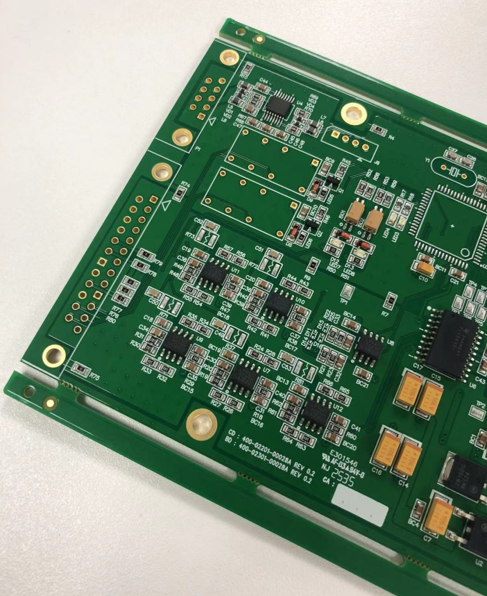
What Is a Ceramic Capacitor?
A ceramic capacitor is a passive electronic component that stores electrical energy using a ceramic dielectric between conductive electrodes.
Unlike electrolytic capacitors, ceramic capacitors generally do not use a liquid electrolyte. Their solid ceramic dielectric allows manufacturers to produce extremely small components with relatively low parasitic resistance and inductance.
The basic structure consists of:
- Ceramic dielectric layers
- Internal metal electrodes
- External terminations
- Protective body material
In modern electronics, the most common form is the multilayer ceramic capacitor (MLCC). Multiple ceramic dielectric layers and electrodes are stacked together inside a compact package. Increasing the number of active layers allows manufacturers to achieve higher capacitance without dramatically increasing the physical size.
That structure explains why an MLCC can deliver substantial electrical performance while occupying only a few square millimeters of PCB area.
Why Ceramic Capacitors Are So Widely Used
The popularity of ceramic capacitors comes from a combination of electrical and manufacturing advantages.
Low ESR and ESL
Ceramic capacitors generally have low equivalent series resistance (ESR) and low equivalent series inductance (ESL). As a result, they can respond quickly to transient changes in current.
This characteristic makes them particularly useful for:
- Power supply decoupling
- IC bypassing
- High-frequency noise suppression
- Switching regulator circuits
- Digital logic power rails
For example, when a processor suddenly changes its current demand, the power distribution network can experience a transient voltage disturbance. A properly placed ceramic capacitor can provide a short local current path, reducing the magnitude of that disturbance.
Compact Form Factor
MLCCs are available in extremely small packages, including common surface-mount sizes such as 0201, 0402, 0603, and 0805.
Therefore, designers can place multiple capacitors around an IC without consuming significant board space.
This is especially important for smartphones, wearables, automotive modules, compact industrial electronics, and other applications where PCB real estate is limited.
High-Frequency Performance
Ceramic capacitors are particularly useful at higher frequencies because their parasitic characteristics can be relatively low compared with many other capacitor technologies.
However, this does not mean every ceramic capacitor behaves identically across all frequencies. The capacitor's self-resonant frequency, package geometry, dielectric, mounting configuration, and PCB layout all influence its actual impedance.
That distinction becomes increasingly important as operating frequencies rise.
Ceramic Capacitor Dielectrics: Why the Material Matters
One of the most important decisions when selecting a ceramic capacitor is the dielectric type.
Two broad categories are especially important in practical PCB design:
- Class 1 ceramic capacitors
- Class 2 ceramic capacitors
Class 1 Dielectrics
Class 1 materials, such as C0G/NP0, provide excellent stability.
Their capacitance changes relatively little with:
- Temperature
- Applied voltage
- Aging
- Operating conditions
Consequently, C0G capacitors are often used where predictable capacitance is more important than maximum capacitance density.
Typical applications include:
- Precision timing circuits
- RF circuits
- Filters
- Oscillators
- Analog signal processing
- Precision measurement equipment
Class 2 Dielectrics
Class 2 materials such as X7R, X5R, and Y5V provide much higher capacitance density.
For example, X7R ceramic capacitors are widely used for power decoupling because they provide a useful balance between capacitance, size, temperature stability, and cost.
However, Class 2 capacitors have an important characteristic that designers cannot ignore: capacitance can decrease under DC bias.
This phenomenon is known as DC bias derating.
DC Bias: The Ceramic Capacitor Specification Engineers Often Miss
Suppose a schematic specifies a 10 µF ceramic capacitor.
It is tempting to assume that the capacitor will provide 10 µF whenever it is operating. In reality, the effective capacitance may be significantly lower when a DC voltage is applied.
The reduction depends on factors such as:
- Dielectric type
- Rated voltage
- Package size
- Applied voltage
- Manufacturer
- Internal construction
For instance, a high-capacitance MLCC operating close to its rated voltage may provide substantially less effective capacitance than its nominal value suggests.
Therefore, capacitor selection should consider effective capacitance under actual operating conditions, rather than relying only on the nominal value printed in the component database.
This matters particularly in DC/DC converters, LDO circuits, processor power rails, and other applications where a minimum capacitance is required for stability or transient performance.
X7R vs X5R vs C0G: Which Ceramic Capacitor Should You Use?
The dielectric designation provides useful information about expected performance.
Dielectric | Typical Characteristics | Common Applications |
C0G/NP0 | Very stable, low loss | RF, filters, precision circuits |
X7R | Good stability and high capacitance | Decoupling, power supplies |
X5R | High capacitance with moderate stability | General-purpose decoupling |
Y5V | Very high capacitance density but greater variation | Less demanding applications |
For general PCB power decoupling, X7R and X5R are frequently encountered.
For precision analog and RF applications, C0G/NP0 can be a better choice.
The key point is that higher capacitance is not automatically better. The correct dielectric depends on what the capacitor is expected to do in the circuit.
Ceramic Capacitor vs Electrolytic Capacitor
Ceramic capacitors and electrolytic capacitors often coexist on the same PCB because they serve different roles.
A ceramic capacitor typically provides excellent high-frequency response and low parasitic impedance. An electrolytic capacitor, meanwhile, can offer relatively large capacitance in applications requiring bulk energy storage.
Consider a switching power supply.
A larger capacitor may handle lower-frequency load variations, while smaller ceramic capacitors positioned close to switching devices or IC power pins address higher-frequency components.
Therefore, capacitor selection is often a system-level design decision rather than a component-level decision.
The goal is not necessarily to replace every capacitor with a ceramic device. Instead, engineers often combine capacitor technologies to achieve the required impedance profile across the relevant frequency range.
The PCB Layout Can Matter as Much as the Capacitor
A technically excellent ceramic capacitor can perform poorly if it is placed incorrectly.
This is particularly obvious in IC decoupling applications.
The capacitor should generally be positioned as close as practical to the IC power and ground connections. The current loop should also be kept short.
Why?
Because PCB traces and vias introduce parasitic inductance.
At high frequencies, even a small amount of inductance can significantly increase impedance. Consequently, the electrical distance between the capacitor and the device can matter more than the physical capacitance value itself.
Consider the Current Path
A typical high-frequency decoupling path can be viewed as:
IC power pin → capacitor → ground → power distribution network
The shorter and more direct this loop is, the lower the unwanted inductance tends to be.
That is why engineers frequently pay attention to:
- Via placement
- Trace length
- Plane configuration
- Pad geometry
- Ground return path
- Capacitor orientation
In high-speed PCB design, the capacitor is therefore not an isolated component. It becomes part of the PCB's power distribution network (PDN).
Why Smaller Packages Are Not Always Better
Miniaturization creates an interesting engineering trade-off.
A smaller MLCC package can provide lower parasitic inductance and consume less PCB area. However, smaller packages can also have lower mechanical robustness.
MLCCs are brittle ceramic structures. Excessive PCB bending, mechanical stress, or improper assembly conditions can cause cracking.
This issue becomes particularly relevant in:
- Automotive electronics
- Large PCBs
- Board-edge locations
- Assemblies exposed to vibration
- Applications involving mechanical shock
PCB designers therefore need to consider both electrical and mechanical reliability.
For example, capacitor placement near PCB edges or areas subjected to bending may require additional attention to component orientation and board strain.
The Hidden Reliability Issue: MLCC Cracking
One of the more important practical issues associated with ceramic capacitors is mechanical cracking.
Because the dielectric material is ceramic, an MLCC is not as mechanically flexible as many other electronic components.
A crack may initially appear harmless. However, if the crack reaches internal electrodes, it can eventually produce electrical failure.
Depending on the failure mechanism, the result may be:
- Open circuit behavior
- Increased leakage
- Intermittent operation
- Short circuit failure
For high-reliability electronics, component placement and PCB assembly processes therefore deserve careful consideration.
Board design, soldering profile, depanelization method, PCB thickness, mounting stress, and mechanical handling can all influence MLCC reliability.
How Ceramic Capacitors Support Power Integrity
Power integrity has become increasingly important as processors, FPGAs, GPUs, networking devices, and automotive controllers demand faster transient current.
When a load changes rapidly, the power supply cannot always respond instantaneously.
The local decoupling network helps bridge this response gap.
A useful conceptual model is:
Voltage fluctuation ≈ transient current × PDN impedance
Reducing PDN impedance therefore helps control voltage variation.
Ceramic capacitors contribute to this objective by providing low-impedance paths over appropriate frequency ranges.
However, using dozens of capacitors indiscriminately is not necessarily the answer. Capacitor selection should be based on:
- Target frequency range
- Effective capacitance
- ESR
- ESL
- Placement
- Power rail requirements
- Load transient characteristics
As a result, modern PDN design increasingly involves impedance analysis rather than simply following a rule such as "put a 0.1 µF capacitor next to every IC."
Ceramic Capacitors in High-Speed and RF PCBs
High-speed digital and RF circuits create additional requirements.
In RF applications, capacitor characteristics such as:
- Q factor
- Self-resonant frequency
- Parasitic inductance
- Dielectric stability
- Package dimensions
can directly influence circuit performance.
For example, a capacitor used in an RF matching network cannot necessarily be selected using the same criteria as a bulk power-decoupling capacitor.
Likewise, high-speed digital designs require careful consideration of the interaction between decoupling capacitors, planes, vias, and return currents.
Consequently, ceramic capacitor selection should always start with the circuit function.
Ask what the capacitor is supposed to accomplish before deciding which capacitance value or package to use.
A Practical Ceramic Capacitor Selection Checklist
When selecting an MLCC for a PCB, engineers can evaluate the following parameters.
1. Capacitance
Choose the required nominal value, but verify effective capacitance under operating conditions.
2. Voltage Rating
Do not select a capacitor solely because its rated voltage exceeds the nominal circuit voltage. Adequate margin should also account for transient conditions and DC-bias effects.
3. Dielectric
Select C0G/NP0, X7R, X5R, or another dielectric according to stability and capacitance requirements.
4. Package Size
Consider both electrical parasitics and mechanical reliability.
5. Temperature Range
Verify that the capacitor can operate across the actual environmental temperature range.
6. ESR and ESL
These parameters become especially important in switching regulators, high-speed digital circuits, and RF applications.
7. DC Bias Characteristics
Check the manufacturer's capacitance-versus-voltage curve when effective capacitance is critical.
8. Mechanical Stress
Evaluate whether the component will be exposed to PCB flexing, vibration, thermal cycling, or assembly stress.
9. Availability
For production designs, component availability and lifecycle status can be just as important as electrical specifications.
A theoretically perfect capacitor is of limited value if it cannot be reliably sourced at production volume.
Ceramic Capacitors and PCB Manufacturing
Component selection does not end with the schematic.
The selected ceramic capacitor must also be compatible with the PCB design and assembly process.
Pad dimensions, solder paste volume, component spacing, reflow profile, board thickness, and assembly tolerances can all influence production quality.
For high-density PCB assemblies, manufacturability should be considered before the design reaches mass production. Working with a PCB and PCBA manufacturer such as PCBMASTER can help engineers evaluate component placement, assembly requirements, and manufacturability considerations alongside PCB production requirements.
This becomes increasingly important for designs combining tiny MLCCs with fine-pitch ICs, HDI structures, rigid-flex construction, or high-density SMT assembly.
The Future of Ceramic Capacitors Is Closely Tied to PCB Density
Modern electronic products continue to become smaller while simultaneously demanding higher processing power, faster communication, and greater electrical efficiency.
That trend creates a difficult engineering problem: more components and higher electrical performance must fit into less physical space.
Ceramic capacitors are well suited to this environment because their multilayer construction enables high capacitance density in extremely small packages.
At the same time, miniaturization creates new challenges involving:
- Mechanical reliability
- DC-bias derating
- Thermal behavior
- Component availability
- Automated assembly
- PCB layout density
- Power integrity
Therefore, the future of ceramic capacitor technology is not simply about increasing capacitance. It is about achieving a better balance between capacitance density, electrical performance, reliability, manufacturability, and cost.
Final Thoughts
The ceramic capacitor is a deceptively simple component. Its schematic symbol may occupy only a few millimeters of drawing space, yet its behavior can influence everything from power-rail stability to RF performance and long-term product reliability.
The most effective approach is to evaluate the capacitor as part of the entire electrical system.
Rather than asking only "What capacitance do I need?", engineers should ask:
What frequency range must this capacitor handle? How much effective capacitance remains under DC bias? Where should it be placed? What parasitic inductance will the PCB introduce? And can the complete assembly remain reliable throughout its operating life?
Those questions turn ceramic capacitor selection from a basic BOM exercise into a genuine PCB engineering decision.
For modern electronics, that distinction matters. A tiny ceramic capacitor may be inexpensive and nearly invisible on the finished board, but when correctly selected and properly integrated into the PCB layout, it can play a critical role in making the entire system work as intended.
Discussions
Become a Hackaday.io Member
Create an account to leave a comment. Already have an account? Log In.