 pcbmaster
A power supply can look electrically correct on a schematic and still behave badly on the bench.
The regulator may have the right input voltage. The output may measure exactly 5 V or 3.3 V with a multimeter. Every component may match the BOM. Yet the board can reboot when a radio transmits, produce unexpected ripple, fail an EMC test, or become unstable only under a particular load.
Very often, power supply capacitors are part of the explanation.
They are not simply passive components added to “smooth the voltage.” Their capacitance, ESR, ESL, voltage rating, dielectric, package size, temperature behavior, and PCB placement all influence how a power supply responds to real electrical events.
That becomes especially important on modern PCBs, where switching regulators, high-speed processors, wireless modules, motor drivers, sensors, and power amplifiers can create fast and unpredictable current transients.
This article takes a practical PCB-level look at power supply capacitors: what they actually do, why one capacitor is rarely enough, how capacitor characteristics change in real circuits, and what to check when a supposedly well-designed power rail does not behave as expected.
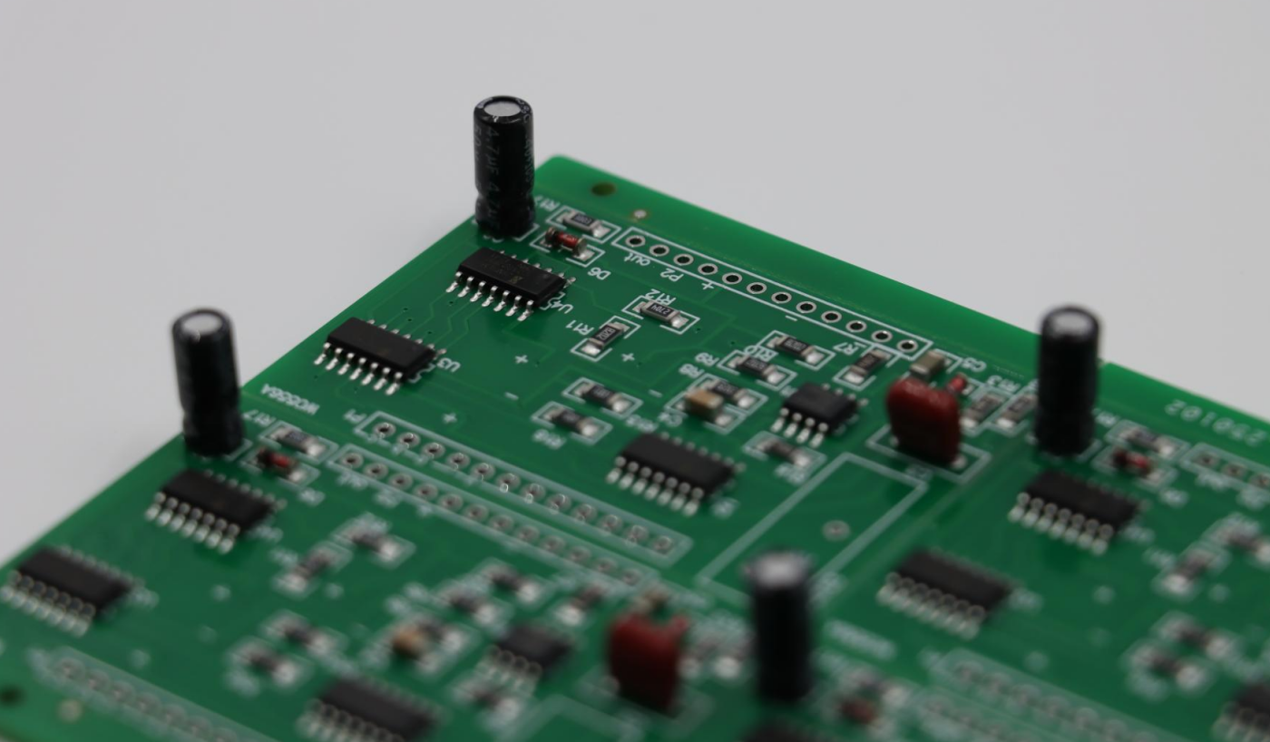
What Are Power Supply Capacitors Actually Doing?
The basic job of a capacitor in a power supply is to store electrical energy and release it when required.
But that simple description hides several different functions.
A typical power rail may use capacitors for:
- Input voltage stabilization
- Output voltage filtering
- Ripple reduction
- Transient response
- High-frequency noise suppression
- Energy storage
- Decoupling between loads and the power source
- Control-loop stability
These functions overlap, but they are not identical.
For example, a large electrolytic capacitor might be excellent at storing energy for relatively slow load changes. It is not necessarily the best component for suppressing a very fast transient at an IC power pin.
Conversely, a small ceramic capacitor can respond extremely quickly, but its effective capacitance may be substantially lower than the number printed on the datasheet.
That is why practical power distribution networks often use multiple capacitor technologies and values rather than searching for one “perfect” capacitor.
Bulk Capacitance vs. High-Frequency Decoupling
One useful way to understand power supply capacitors is to divide their jobs by frequency.
Bulk capacitors
Large electrolytic, polymer, or tantalum capacitors provide relatively high energy storage.
They can help handle:
- Large load changes
- Low-frequency ripple
- Cable-induced voltage fluctuations
- Converter input current pulsation
- Power rail energy requirements
For example, a motor controller may experience substantial current variation when a motor accelerates. A nearby bulk capacitor can provide part of that transient current without forcing the upstream supply and PCB traces to respond instantaneously.
Ceramic capacitors
MLCCs are commonly used closer to switching regulators and ICs because their low ESR and low ESL allow them to respond effectively to high-frequency current changes.
A 100 nF ceramic capacitor placed directly beside an IC power pin is doing a very different job from a 470 µF bulk capacitor located elsewhere on the board.
The two should not necessarily be viewed as competing components.
They form different parts of the power distribution network.
Why multiple values are common
A practical rail might contain:
- A bulk capacitor near the power-entry point
- Additional bulk capacitance near a regulator
- Several µF of ceramic capacitance around the regulator
- Smaller ceramic capacitors close to individual ICs
- Very small capacitors for particularly fast switching currents
However, adding capacitors indiscriminately is not automatically an improvement. The interaction between capacitance, ESR, ESL, regulator control loops, and PCB parasitics matters.
The Number on the Capacitor Is Not the Whole Story
Suppose a design calls for a 10 µF ceramic capacitor.
It is tempting to assume that the circuit simply receives 10 µF.
Real hardware can be very different.
MLCCs, particularly Class 2 ceramic capacitors such as X5R and X7R types, can exhibit significant DC bias derating. Their effective capacitance decreases as the applied voltage increases.
A capacitor marked 10 µF may therefore provide considerably less than 10 µF at its operating voltage.
Temperature and aging can also affect the actual capacitance.
This creates an important distinction:
Nominal capacitance is a component specification; effective capacitance is a circuit property.
For power supply design, the second one is usually more important.
When selecting an MLCC, engineers should therefore examine the manufacturer's DC-bias curves rather than relying exclusively on the nominal value.
Voltage Rating Matters More Than It Looks
Running a capacitor close to its voltage rating is rarely a good strategy.
A higher voltage rating can provide greater reliability margin, but it can also affect capacitance, package size, and electrical characteristics.
For example, consider a 12 V rail.
Choosing a capacitor rated for exactly 12 V leaves little margin for:
- Startup overshoot
- Transient events
- Supply variation
- Inductive spikes
- Regulator behavior
- Measurement uncertainty
A 25 V-rated capacitor may be a much more appropriate choice depending on the application.
For automotive and industrial electronics, this becomes even more significant because the nominal system voltage may be only one part of the actual electrical environment.
ESR and ESL: The Parasitics You Cannot Ignore
An ideal capacitor would have zero resistance and zero inductance.
Real capacitors do not.
Two parameters are particularly important:
ESR — Equivalent Series Resistance
ESR represents the resistive component associated with the capacitor.
It affects:
- Ripple voltage
- Power dissipation
- Damping
- Transient response
Lower ESR is often desirable, but lower is not universally better.
Some regulator control loops are designed around a particular output-capacitor ESR range. Replacing a capacitor with an extremely low-ESR ceramic device can potentially change the behavior of the regulator.
ESL — Equivalent Series Inductance
ESL becomes increasingly important as frequency rises.
Even an excellent capacitor cannot respond instantaneously if current must travel through a long PCB trace, via structure, or package connection.
This leads to one of the most important practical rules for PCB power design:
The electrical distance between the capacitor and the load matters, not just the physical distance.
A capacitor sitting a few millimeters away with a poor current path may perform worse than expected.
Placement Can Matter More Than Capacitance
A common PCB design mistake is to choose the correct capacitor but place it in the wrong location.
Consider a switching regulator.
The high-frequency switching current flows through a relatively small current loop. The input capacitor should be positioned so that the loop between the regulator switching path, capacitor, and return path is as small as practical.
Long traces add parasitic inductance.
At high frequencies, that inductance can become significant enough to undermine the capacitor's intended function.
Therefore, instead of asking:
“Did I put a 10 µF capacitor on the input?”
ask:
“Did I place the 10 µF capacitor where the switching current actually needs it?”
That is a much more useful engineering question.
The Return Path Is Part of the Capacitor
Another frequently overlooked issue is the return connection.
A capacitor is connected between two nodes. Its effectiveness depends on the complete current loop, not simply on one short connection to the power plane.
For high-frequency decoupling, the return path should have low inductance.
This is why designers often place a ceramic capacitor close to an IC power pin and connect it directly to a nearby ground plane through appropriately placed vias.
A long ground trace can introduce enough inductance to reduce the capacitor's effectiveness at higher frequencies.
In other words:
Capacitor placement and ground-plane design should be considered together.
Why a Power Rail Can Still Have Ripple
A multimeter can report a stable voltage while an oscilloscope reveals significant ripple.
That is because a multimeter generally does not show the complete high-frequency behavior of a power rail.
Ripple can originate from:
- Switching regulator operation
- Load transients
- Poor capacitor selection
- Insufficient capacitance
- Excessive ESR
- PCB parasitic inductance
- Poor grounding
- Switching-node coupling
- Inadequate layout
The measurement itself can also create misleading results.
A long oscilloscope ground lead can act like an antenna and introduce apparent ringing or noise that is not representative of the actual circuit.
For meaningful power-integrity measurements, engineers should minimize the measurement loop, use an appropriate probe connection, and examine both the steady-state ripple and transient response.
More Capacitance Does Not Always Mean Better
This is one of the easiest traps in power-supply design.
Suppose an output rail is unstable or exhibits voltage dips. Adding more capacitance seems like an obvious solution.
Sometimes it works.
Sometimes it makes the problem worse.
The regulator's control loop was designed to operate with a particular output network. Changing the capacitance and ESR can alter the loop response, phase margin, startup behavior, and transient characteristics.
Some converters specify:
- Minimum output capacitance
- Maximum output capacitance
- Required ESR range
- Recommended capacitor types
- Specific capacitor placement
Those recommendations are not arbitrary.
Therefore, before increasing capacitance, check the regulator datasheet and, where available, the manufacturer's stability analysis or reference design.
Capacitor Technology Should Match the Job
Different capacitor technologies have different strengths.
Capacitor Type | Typical Strength | Common Power-Supply Role |
MLCC | Low ESR/ESL, compact | High-frequency decoupling, regulator filtering |
Aluminum electrolytic | High capacitance, economical | Bulk energy storage |
Polymer | Low ESR, good ripple performance | Output filtering and bulk capacitance |
Tantalum | Compact bulk capacitance | Power filtering where appropriate |
Film | Stable characteristics | Specialized power and filtering applications |
The choice depends on voltage, capacitance, ripple current, temperature, lifetime, size, cost, and reliability requirements.
For demanding products, engineers may deliberately combine capacitor technologies to cover different frequency ranges and operating conditions.
Power Supply Capacitors and PCB Manufacturing
Capacitor performance does not exist independently from PCB manufacturing.
A power circuit can be theoretically correct while PCB construction introduces problems through:
- Excessive via inductance
- Poor copper distribution
- Narrow current paths
- Inadequate copper thickness
- Incorrect layer transitions
- Poor grounding
- Excessive loop area
- Component placement constraints
For multilayer PCBs, the stack-up can also influence power-distribution impedance.
A solid reference plane located appropriately beneath a power layer or signal layer can reduce loop inductance and improve the overall electrical behavior of the board.
For higher-performance designs, PCBMASTER engineers may need to consider capacitor placement together with stack-up, current return paths, thermal requirements, and DFM constraints rather than treating component placement as a separate task.
A Practical Way to Debug a Bad Power Rail
When a power rail misbehaves, changing capacitors randomly is rarely an efficient debugging strategy.
A better process is systematic.
1. Measure the rail at the load
Do not only measure the voltage at the regulator output.
Check the voltage where the actual IC or load receives power.
2. Look at startup
Check:
- Rise time
- Overshoot
- Undershoot
- Oscillation
- Soft-start behavior
3. Apply a realistic load
A rail that looks perfect with no load may behave very differently under dynamic load.
4. Examine ripple with proper probing
Use a short ground connection and appropriate bandwidth settings.
5. Check the capacitor datasheet
Verify:
- Effective capacitance
- Voltage rating
- ESR
- Temperature characteristics
- Ripple-current rating
- Aging
- Package size
6. Inspect the PCB layout
Look specifically at the current loop between:
Power source → capacitor → switching/load path → return
7. Compare against the regulator reference design
Reference layouts can reveal problems that are difficult to identify from the schematic alone.
What About Capacitor Placement Around an IC?
For digital ICs, a common strategy is to place small ceramic capacitors near the power pins.
The exact value and quantity depend on the IC and its operating characteristics, but the principle is straightforward:
The capacitor should be close enough to supply the local transient current before the rest of the power-distribution network responds.
This is particularly relevant for processors, FPGAs, memory, communication chips, ADCs, and other devices with rapidly changing current consumption.
For multi-rail devices, each rail should be considered independently.
A single large capacitor somewhere on the board cannot necessarily replace local decoupling at every high-speed load.
Watch Out for Mechanical and Reliability Issues
MLCCs have another interesting characteristic: they can be mechanically sensitive.
Large ceramic capacitors mounted on rigid PCBs can be vulnerable to board flexure, especially when placed near PCB edges, mounting holes, or areas exposed to mechanical stress.
Cracked MLCCs can lead to electrical failures ranging from increased leakage to short circuits.
For products exposed to vibration, thermal cycling, or mechanical stress, capacitor selection should therefore consider mechanical reliability as well as electrical specifications.
This is another reason why component selection, PCB layout, assembly, and reliability should be treated as one engineering problem.
Designing Power Supply Capacitors for Real Hardware
A reliable power rail is not created by choosing the largest capacitance value in the catalog.
The better approach is to understand the electrical environment first:
- Determine the load profile.
- Identify expected transient currents.
- Understand the regulator's stability requirements.
- Select capacitor technology accordingly.
- Check effective capacitance under DC bias.
- Provide sufficient voltage and temperature margin.
- Minimize high-frequency current loops.
- Design low-inductance return paths.
- Validate ripple and transient response on the actual PCB.
- Consider manufacturing and reliability constraints before finalizing the layout.
This approach also makes troubleshooting much easier because each capacitor has a defined electrical purpose.
The Bigger Picture: Capacitors Are Part of the Power Distribution Network
Perhaps the most useful way to think about power supply capacitors is to stop treating them as isolated components.
A capacitor works together with:
- PCB copper
- Vias
- Power planes
- Regulator switching elements
- Inductors
- IC power pins
- Ground planes
- Connectors
- Cables
- The load itself
Together, these elements form the power distribution network (PDN).
The PDN determines how effectively a board can maintain a stable voltage when current changes.
That perspective explains why a capacitor with an excellent datasheet can still perform poorly on a badly laid-out PCB—and why a carefully designed capacitor network can make a dramatic difference to an otherwise ordinary power supply.
For engineers working on real hardware, that is the part worth remembering.
The goal is not simply to add capacitance. The goal is to give transient current the shortest, lowest-impedance path possible.
Once that principle becomes part of the PCB design process, selecting and placing power supply capacitors becomes much less of a trial-and-error exercise and much more of an engineering decision.
Discussions
Become a Hackaday.io Member
Create an account to leave a comment. Already have an account? Log In.