 Sergey Novikov
This article discusses how to transfer data in packets via the baremetal no-os application on the ad9361. The liqid-dsp library, which is compiled for the arm core in the zynq-7000, is used to generate the frame on the transmitting side and process the frame on the receiving side. To relay messages, the BFS graph traversal algorithm (Breadth-First Search, breadth-first search) and a simple addressing system for transceivers in the payload of a message packet are used.
I am not an expert in ad9361 programming. This is an area that I want to explore. I'm trying to figure out the basics and it's easier for me to learn when I see how it works. That's why I'm doing this. Not because I already know everything about the ad9361. And if you also learn something from reading my article, that would be great. But please don't rely on my articles to understand the theory. There are many excellent books and other sources on this topic where you can find more information. I hope that through this article you will learn how to apply some of the basic principles of ad936x programming in real systems. If you notice a bug or something that can be improved, please write to me in the comments or private messages. Then we can study together, and maybe I can fix it and show it in new articles.
Breadth-first graph traversal algorithm
As you know, a huge advantage of this algorithm is that the paths it searches for in an unweighted graph are the shortest. Thus, this algorithm will search for paths with the minimum number of edges.
First, we take turns going to all the vertices that are at a distance of 1. If we have vertices A, B, and C that lie in the adjacency list from the starting vertex x, then vertex A is considered first. Then we move from it to vertex B, and from vertex B we move to vertex C. We will go through all the vertices that are at a distance of 1.
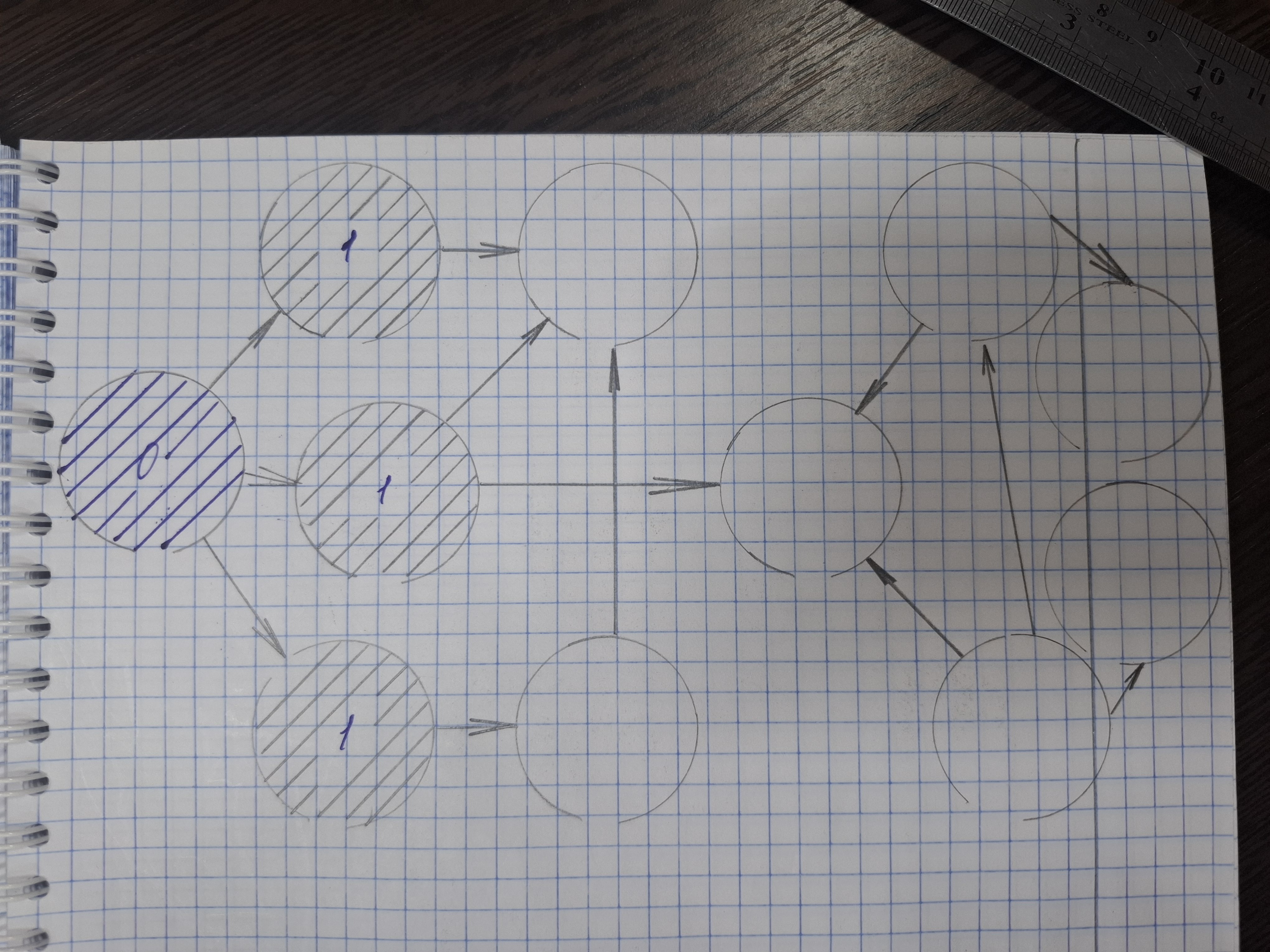
Fig. 1
Then, when they are over, we will go along the peaks at a distance of 2.
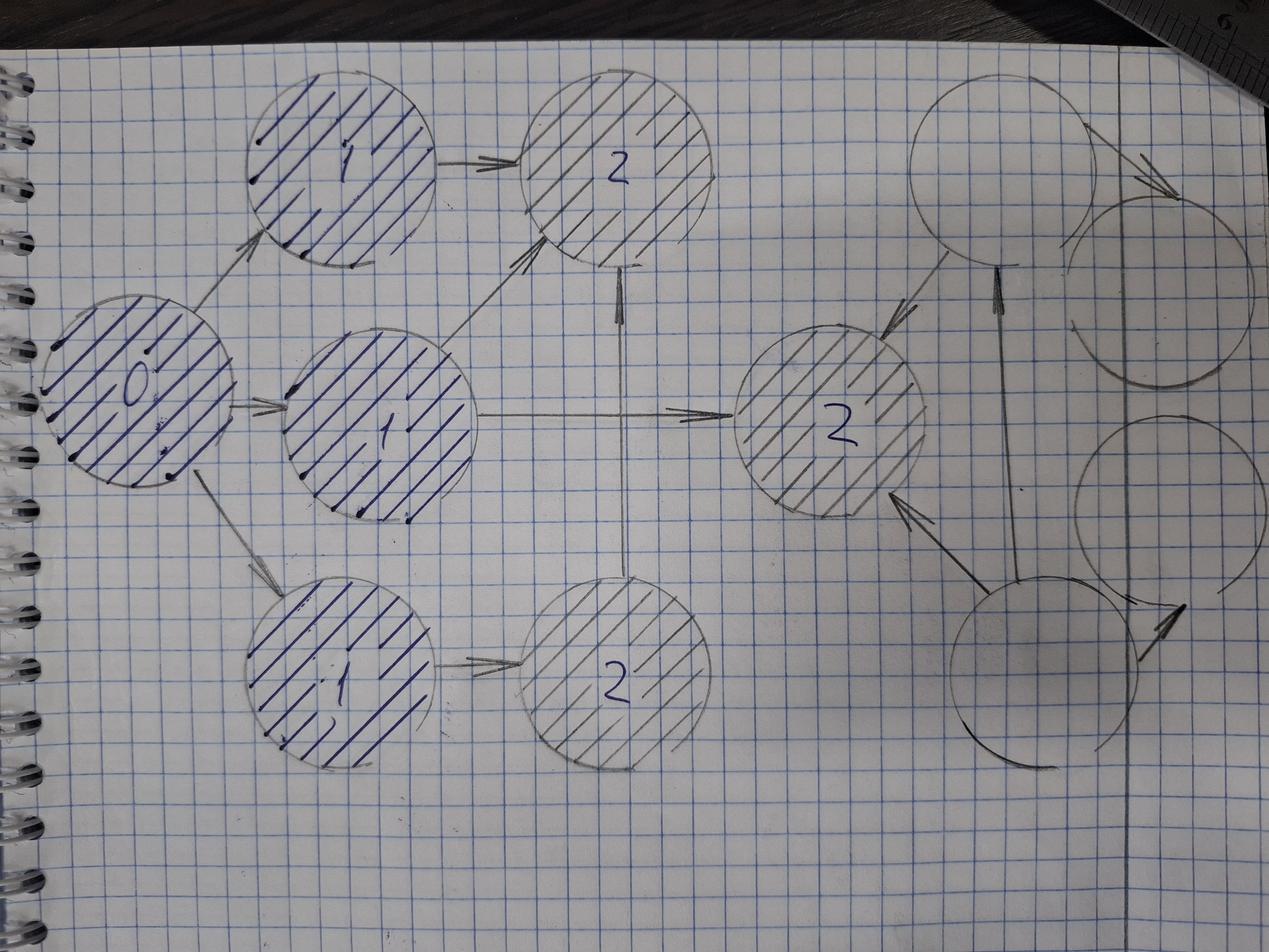
Fig. 2
Then follow the vertices at a distance of 3.
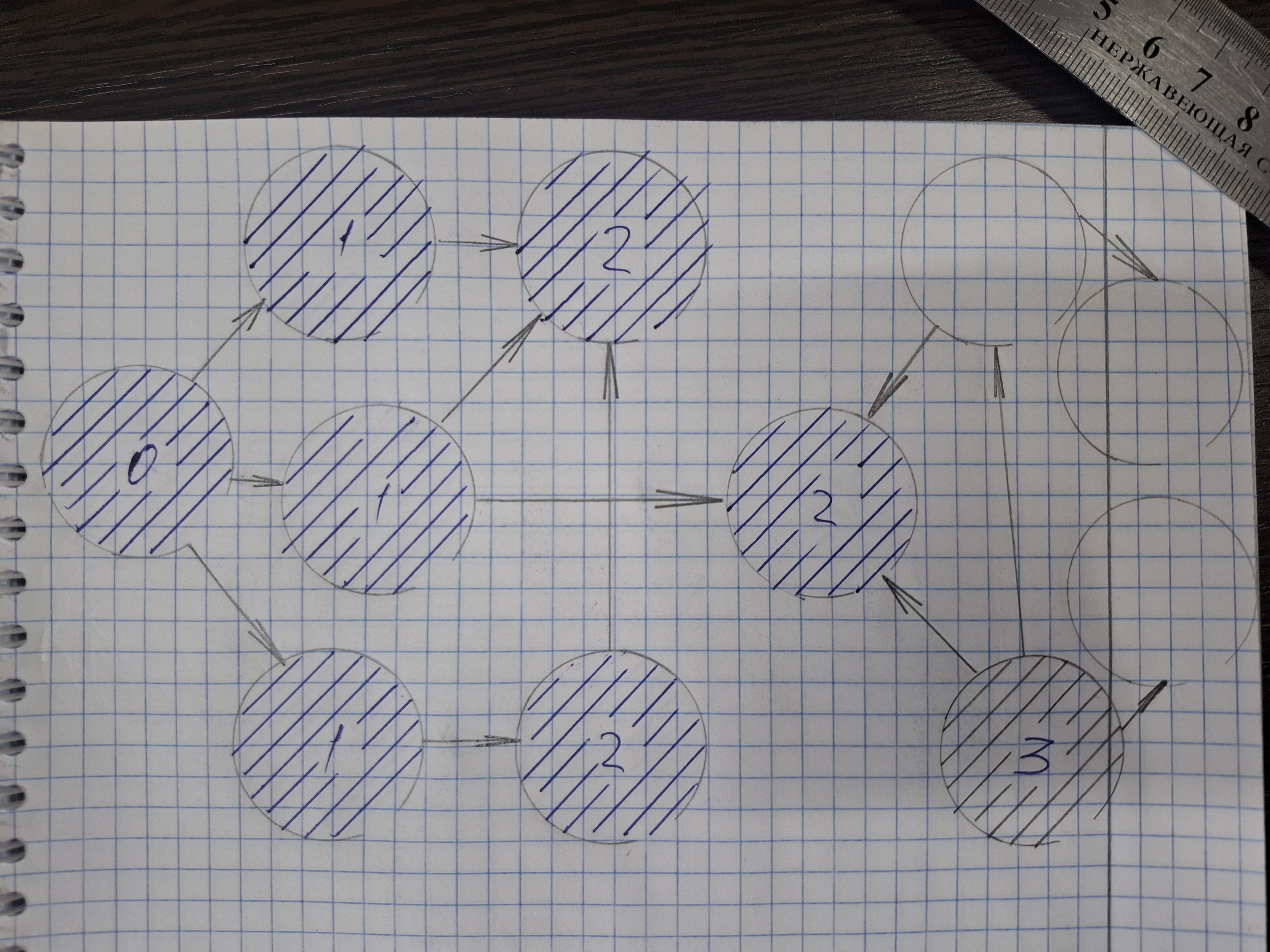
Fig. 3
4 and 5
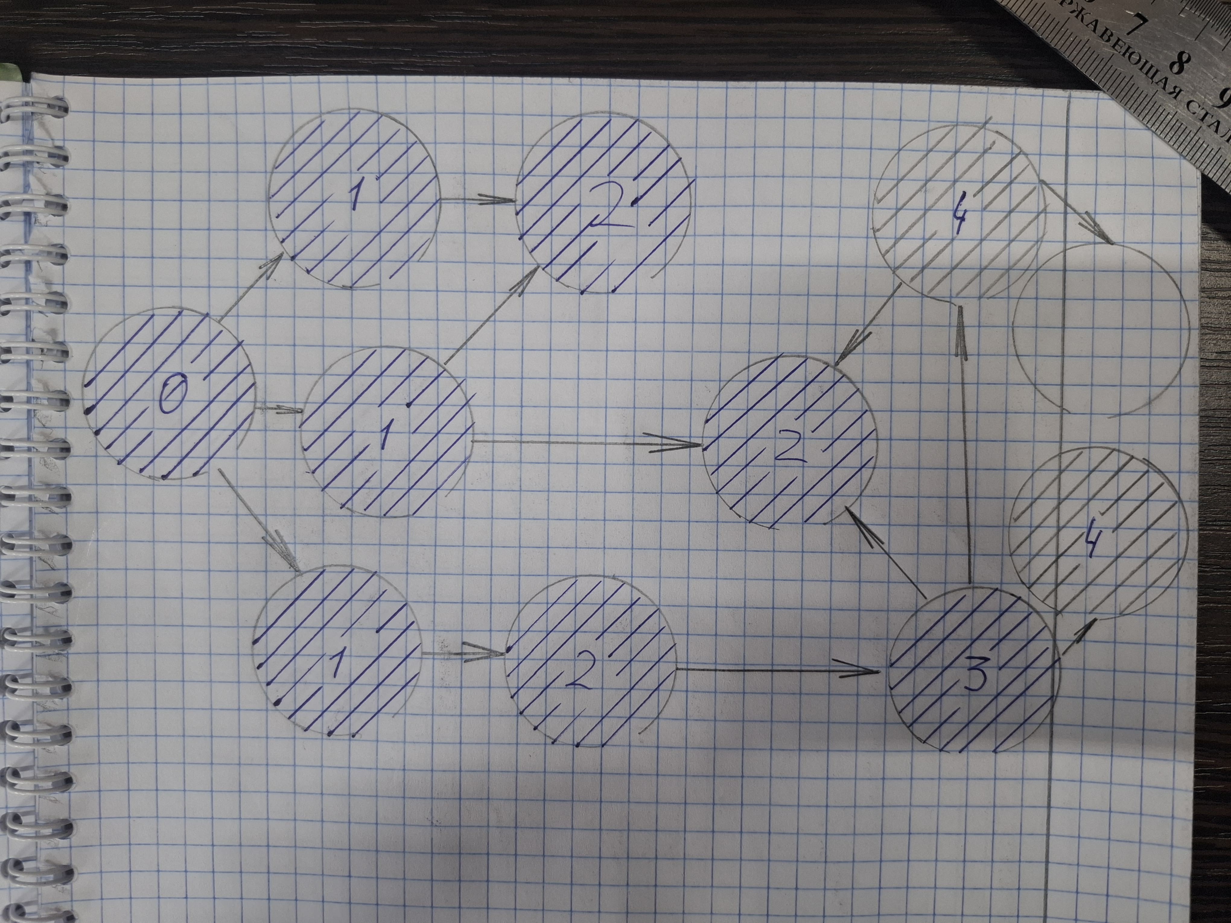
Fig. 4
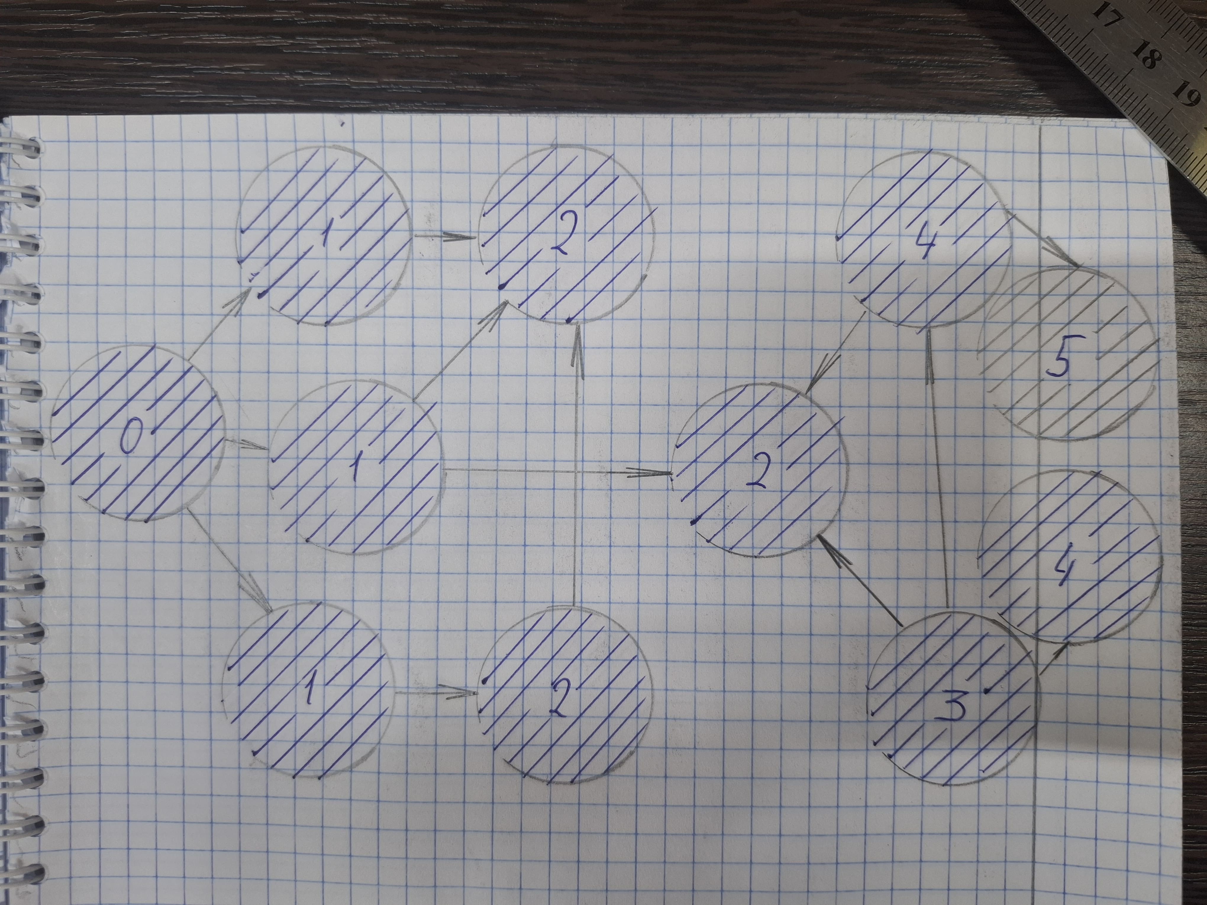
Fig. 5
This is how we will go through the layers. And diverge further and further and further from the starting point.
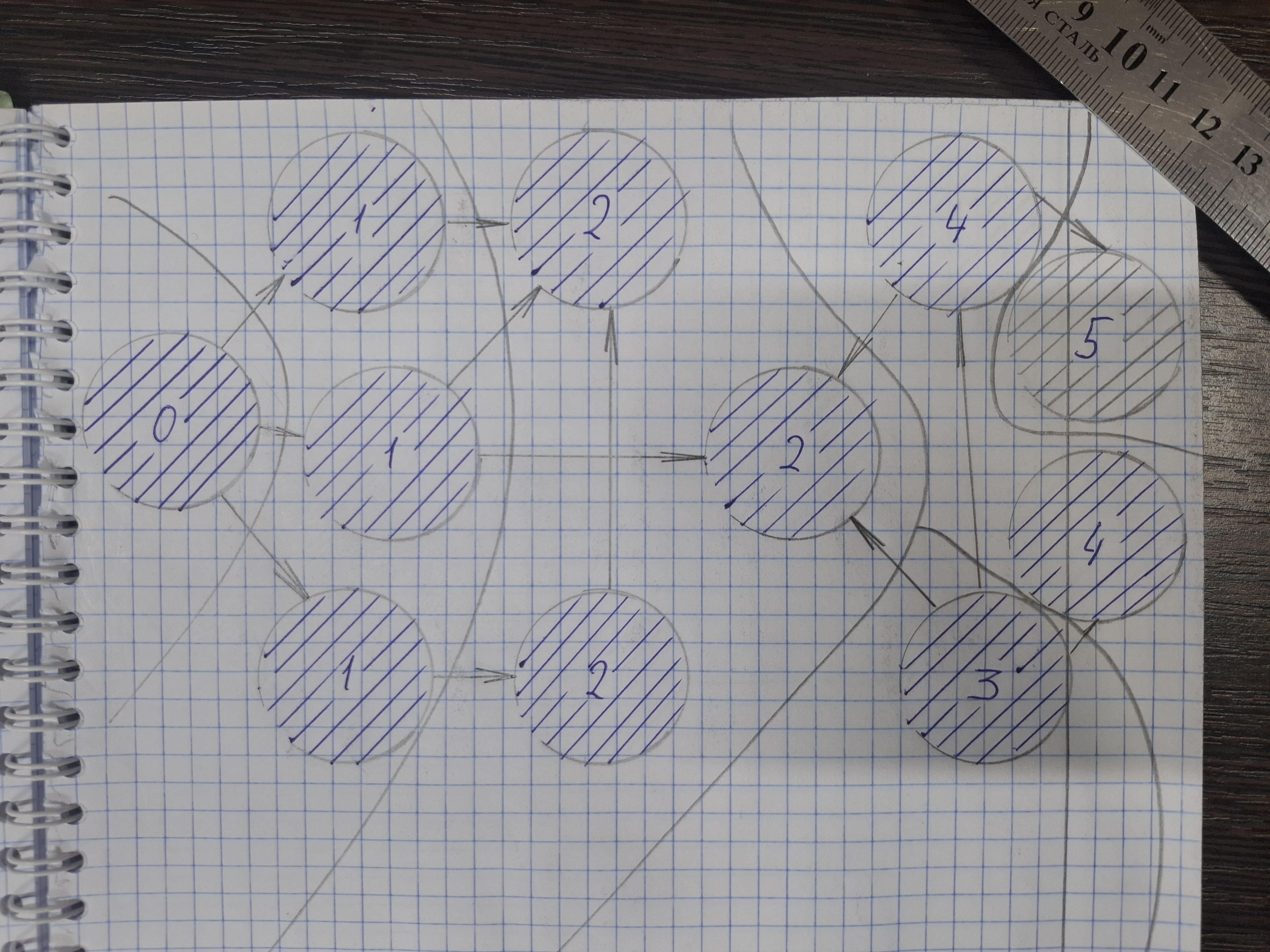
Fig. 6
When we traverse the graph and consider the vertices that are adjacent to the vertex V. Let's add the vertices that we want to consider to the queue. Thus, when we consider them in layers, we will first consider vertices at a distance of 0. Then we add vertices at a distance of 1 to the queue and consider them. And after we consider them at a distance of 1, we will add vertices at a distance of 2 to the queue. If we are going to run a breadth-first traversal from some vertex V, we need to create two arrays. The array dist[i] is the distance from V to i. And the visited[i] array, which stores information about whether a vertex has been added to the queue. Then:
void bfs(int v){ // v is the initial vertex
  push(v); // adding the starting vertex to the queue
  visited[v]= true;
  dist[v] = 0; // the distance to the starting vertex is 0

  // while there is something in the queue
  while(queueSize() > 0){
  // taking the first vertex out of the queue
  int x = queuePop();

  // iterating over all edges from vertex x
  // to the vertices of i, which are still white
  for(int i : G[x])
    if(!visited[i]){
      // adding to the queue and
      // we assign a distance of 1 more
      queuePush(i);
      visited[i] = true;
      dist[i] = dist[x] + 1;
    }
  }
}
In the end, when the algorithm finishes its work, all the vertices that can be reached will be marked as visited. The dist distance will be calculated for all the vertices that you managed to reach.
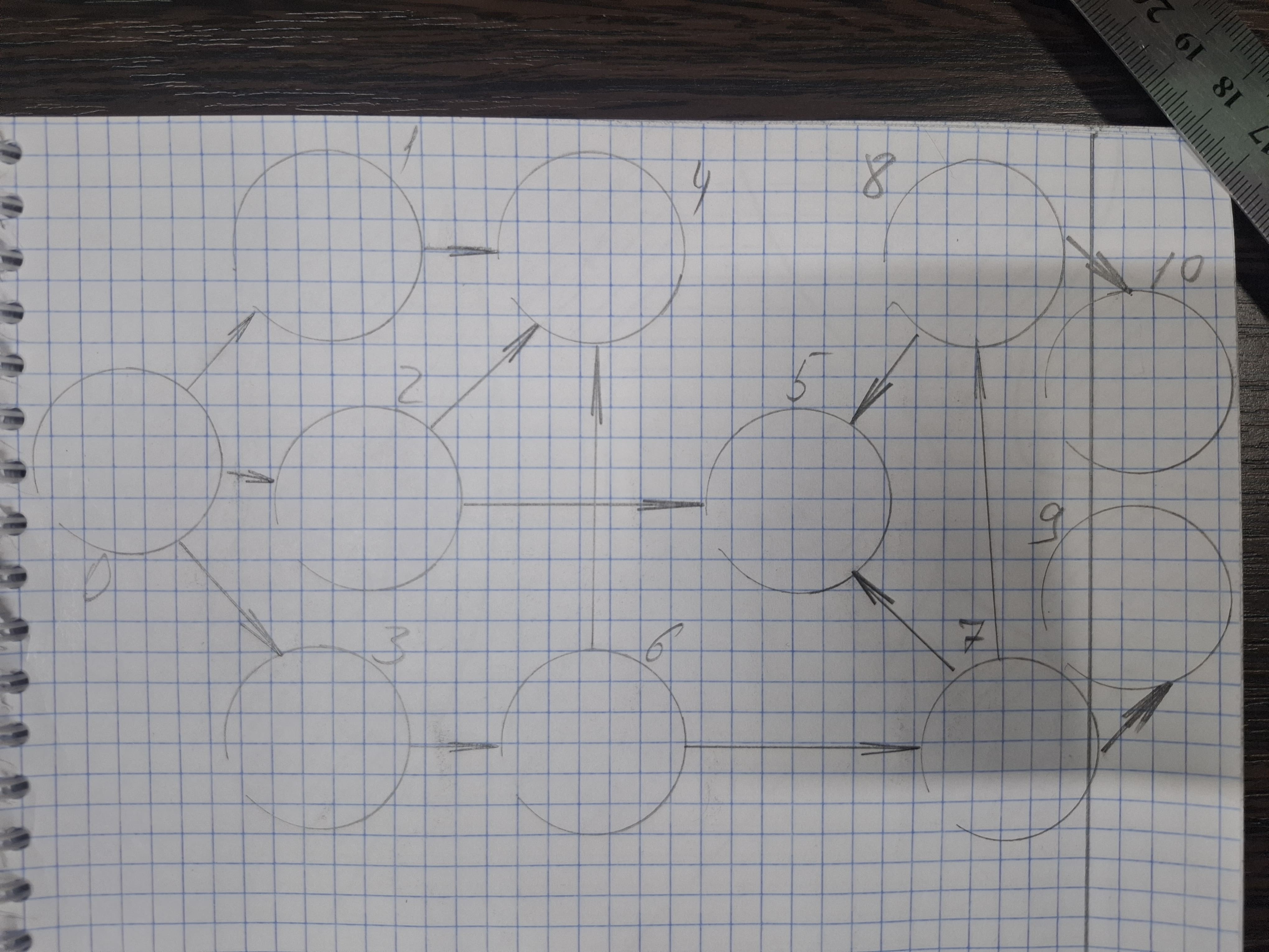
Fig. 7
For example, on such a graph, we will first add vertex 0 to the queue. Then we will extract vertex 0 from the queue and add all the vertices that are reachable from it. [0] -> [1, 2, 3]. In the next step, we will extract vertex 1 and add everything that is achievable from it, in this case the vertex 4 - [1, 2, 3] -> [2, 3] -> [2, 3, 4]. Let's extract vertex 2 and see that you can get to 4 from it (it's already in our queue) and you can get to 5 - [2, 3, 4] -> [3, 4] -> [3, 4, 5]. Etc.
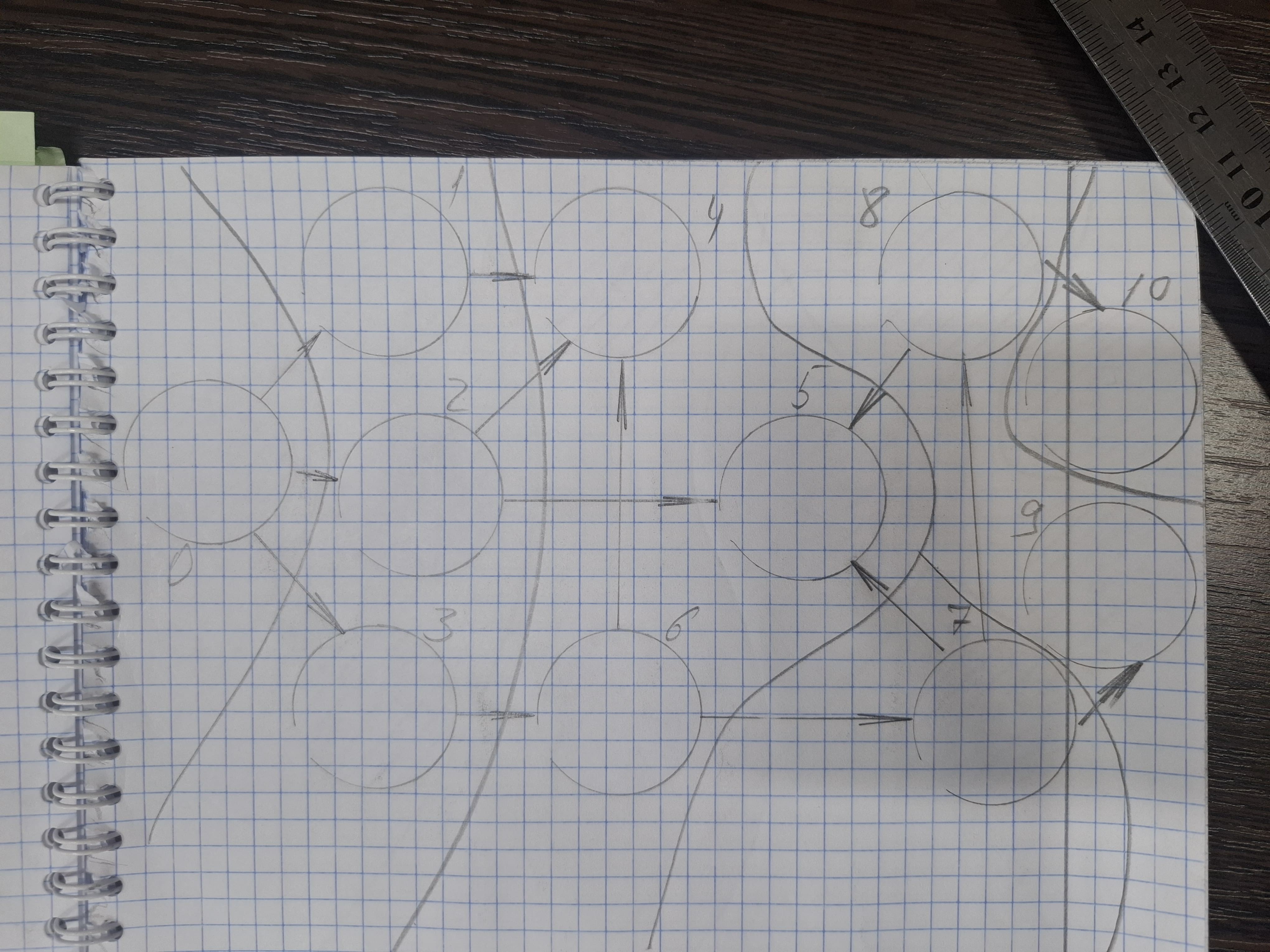
Fig. 8
When the vertices are considered, we first consider the vertices at a distance of 1 according to the construction of the algorithm. Then we will use them in turn to build all the vertices at distance 2, and so on. You can see that the vertices are at the same distance in a row in a queue. First 0, then 1, 2, 3, then 4, 5, 6, then 7, then 8, 9, then 10. In the dist array, we will have the shortest distance, taking into account that our edges are the same.
To summarize, we can imagine the transceivers, which are located on a certain area, as the vertices of the graph. And if there is a connection between the transceivers, then this can be represented as an edge. Then it turns out that this is an unweighted graph. To transfer a data packet from one node to another, you can perform a breadth-first traversal. Then the node numbers that need to be traversed will be known in order to make as few relays as possible.
Laboratory work on data transmission with retransmission
To generate the frame, we will use the liqud-dsp library and transceivers in the form of PlutoSDR clones. In one of the previous articles, it was described how to program the ad9361, but this time you will have to compile the liquid-sdr library for the ARM core zynq-7000.
Liquid-dsp compilation for arm zynq-7000
We clone the liquid-dsp repository and export arm-none-eabi. The command $arm-none-eabi-gcc --version should return the version number. In the README.The MD of the liquid-dsp repository says what needs to be done $ ./bootstrap.sh . Then the most interesting part
cmake ..\
-DCMAKE_C_COMPILER=arm-none-eabi-gcc \
-DCMAKE_CXX_COMPILER=arm-none-eabi-g++ \
-DCMAKE_SYSTEM_NAME=Generic \
-DCMAKE_C_FLAGS="-mcpu=cortex-a9 -mfpu=vfpv3 -mfloat-abi=hard -ffrecstanding" \ # => это как в xilinx.mk в scripts/tools в корне проекта
-DCMAKE_EXE_LINKER_FLAGS="-hostdlib" \
-DCMAKE_TRY_COMPILE_TARGET_TYPE=STATIC_LIBRARY \
-DBUILD_EXAMPLES=off \
-DBUILD_AUTOTESTS=off \
-DBUILD_BENCHMARKS=off \
-DBUILD_SUARED_LIBS=off \
-DBUILD_STATIC_LIBS=on \
-DENABLE_SIMD=off \
-DENABLE_AUTOSCRIPT=off \
-DENABLE_LOGGING=off \
-DWITH_FFT=off
After that, there were still errors, but in src/utility/src/memory.c, in the liquid_aligned_alloc function, posix_memalign(&ptr, _alignment ...) should be replaced with ptr=malloc(_size); and then make make clean and make -j1 in the working directory, and the ad9361 project can be assembled with the source code from tutorial framing, for example.
All work was done in UBUNTU version 22.04.5 LTS (Jammy Jellyfish) with 64-bit Linux kernel 5.15.0-190-generic x86_64 MATE 1.26.0. Unlike the previous article, the application is built from source using a Makefile. For this to work, you need to disable O2 optimization. Then the standard example from Analog Devices with DMA and TDD will start working as it should.
To connect the liquid-dsp library and build an example of tutorial framing for a Pluto clone, you need to add a Makefile. In src.mk you must specify the path to liquid-dsp, for example:
# this can be added at the very beginning
LIQUID_PATH=/home/nsv/liquid-dsp
CFLAGS += -I$(PROJECT)/include # this is useful for dividing the code into header and source files
CFLAGS += -I$(LIQUID_PATH)/include
CFLAGS += -I$(LIQUID_PATH)/src
CFLAGS += DARM_CPU=1
CFLAGS += -DLIQUID_USE_COMPLEX_H=1
# and this is added before INC += $(DRIVERS)/rf_transceiver/ad9361...
# we specify the static linking library, we assume that it is assembled and stored in the build-arm
LIQUID_LIB = $(LIQUID_PATH)/build-arm/libliquid.a
# adding the library to LIB_FLAGS (this flag is used in generic.mk )
LIB_FLAGS += $(LIQUID_LIB)
# add a math library
LIB_FLAGS += -lm
After that, you can safely add the source code from the tutorial framing directly to the source code of the ad9361 project from Analog Devices from the 2021_R1 branch (or whatever you want). Then do export XSCT_REMOTE_HOST=127.0.0.1 and export XSCT_REMOTE_PORT=3121, run make and make run, and watch the SERIAL MONITOR output information to the UART from the liquid-sdr operation. Isn't that a miracle?
Frame transmission and reception
The liquid-dsp library generates samples from -1 to 1. This is very clearly seen in the example of tutorial framing. To transfer these samples via ad9361 and the no-os driver from Analog Devices from the 2021_R1 branch, you will have to program. The samples should be adjusted to the range [-32768, 32767]. At the same time, do not overload the ad9361 DAC, but also use it with maximum efficiency.
// 1. We find the maximum amplitude
float max_amp = 0.0f;
for (i = 0; i < buf_len; i++) {
  float amp = cabsf(buf[i]);
    if (amp > max_amp) max_amp = amp;
}
// printf("Max amplitude: %.8f\n", max_amp);

// 2. Calculate the normalization coefficient
float normalize_gain = 0.9f / max_amp;
// printf("Normalize gain: %.3f\n", normalize_gain);
Samples can be stored in the image and likeness of the sine_lut_iq array from the standard example with custom data loading into DMA from Analog Devices.
// allocating memory for DMA
uint32_t *frame_buffer = (uint32_t*)malloc(buf_len * sizeof(uint32_t));
if (!frame_buffer) {
  // error handling
  printf("Error allocating frame_buffer\n");
  return -1;
}

// converting the data
for (i = 0; i < buf_len; i++) {
  // Scale and quantize

  float i_norm = crealf(buf[i]) * normalize_gain;
  float q_norm = cimagf(buf[i]) * normalize_gain;

  int16_t i_val = (int16_t)(i_norm * 32767.0f);
  int16_t q_val = (int16_t)(q_norm * 32767.0f);

  // Overflow check
  if (i_val > 32767 || i_val < -32768) {
    printf("WARNING: i_val overflow at %d: %d\n", i, i_val);
  }
  if (q_val > 32767 || q_val < -32768) {
    printf("WARNING: q_val overflow at %d: %d\n", i, q_val);
  }

  // Packing in uint32_t
  frame_buffer[i] = ((uint32_t)(q_val & 0xFFFF) << 16) | (uint32_t)(i_val & 0xFFFF);
}
Next, the data must be uploaded via DMA
axi_dac_load_custom_data(ad9361_phy->tx_dac, frame_buffer, LIQUID_FRAME64_LEN, (uintptr_t)dac_buffer);
This will work without any problems if you edit the structure. It is important to specify the correct size. The AD9361 is dual-channel and this should be taken into account, the size should be twice as large just for the second channel. Otherwise, if this is not done, the axi_dac_load_custom_data function from the 2021_R1 branch will fill the available size with only half of the frame and framesync64_execute will never detect useful information in the received samples. Of course, you can simplify it by disabling the second channel. And the data is copied manually using memcpy. It's all optional. Now you can do anything with it.
struct axi_dma_transfer transfer = {
  // Number of bytes to write/read
  // .size = sizeof(sine_lut_iq),
  .size = LIQUID_FRAME64_LEN * 2 * sizeof(uint32_t),
  // Transfer done flag
  .transfer_done = 0,
  // Signal transfer mode
  .cyclic = CYCLIC, // CYCLIC
  // Address of data source
  .src_addr = (uintptr_t)dac_buffer,
  // Address of data destination
  .dest_addr = 0
};
After that, you can safely broadcast it, observing the rules and laws regulated by the state in whose territory these experiments take place. Failure to comply with these laws may and will result in liability for violating the use of radio frequencies!
ad9361_set_en_state_machine_mode(ad9361_phy, ENSM_MODE_TX);
ad9361_get_en_state_machine_mode(ad9361_phy, &ensm_mode);
printf("SPI control - TX: %s\n",
ensm_mode == ENSM_MODE_TX ? "OK" : "Error");
no_os_mdelay(10);

uint16_t count_tx = 100;

while(count_tx--){ // count_tx--
  Xil_DCacheFlush();
  /* Transfer the data. */
  axi_dmac_transfer_start(tx_dmac, &transfer);
  /* Flush cache data. */
  // Xil_DCacheInvalidateRange((uintptr_t)dac_buffer,sizeof(sine_lut_iq));
  Xil_DCacheInvalidateRange((uintptr_t)dac_buffer, transfer.size);
  // no_os_mdelay(10);
  if(count_tx==0){
    // Проверка первых 10 семплов в dac_buffer
    for (i = 0; i < 10; i++) {
      int16_t i_val = (int16_t)(dac_buffer[i] & 0xFFFF);
      int16_t q_val = (int16_t)((dac_buffer[i] >> 16) & 0xFFFF);
      printf("dac_buffer[%d]: I=%6d, Q=%6d\n", i, i_val, q_val);
  }
  printf("=====================\n");
}

ad9361_set_en_state_machine_mode(ad9361_phy, ENSM_MODE_ALERT);
ad9361_get_en_state_machine_mode(ad9361_phy, &ensm_mode);
printf("SPI control - Alert: %s\n",
ensm_mode == ENSM_MODE_ALERT ? "OK" : "Error");
no_os_mdelay(1000);
After that, it will be broadcast approximately 100 times for 1,440 samples. And in order to accept them, it is necessary to perform actions in the reverse order. That is, to bring the received samples to the range from -1 to 1.
/* Read the data from the ADC DMA. */
axi_dmac_transfer_start(rx_dmac, &read_transfer);

/* Wait until transfer finishes */
status = axi_dmac_transfer_wait_completion(rx_dmac, 500);
if(status < 0)
  return status;

Xil_DCacheInvalidateRange((uintptr_t)adc_buffer, sizeof(adc_buffer));

convert_adc_buffer(adc_buffer, rx1_samples, (ADC_BUFFER_SAMPLES * ADC_CHANNELS));

// execute synchronizer and receive the entire frame at once
framesync64_execute(fs, rx1_samples, (ADC_BUFFER_SAMPLES * ADC_CHANNELS)/2); // делю
// на 2, потому что не привожу данные с второго канала ацп

где функция convert_adc_buffer представляет собой

void convert_adc_buffer(uint16_t *src, float complex *dst, size_t len) {
    uint16_t j = 0;
    for (size_t i = 0; i < len; i+=4) {
        int16_t i_val = (int16_t)(src[i] & 0xFFFF);
        int16_t q_val = (int16_t)(src[i+1] & 0xFFFF);

        dst[j++] = ((float)i_val * SCALE) + I * ((float)q_val * SCALE);
    }
}
Addressing of transceivers
To summarize, in the last article we managed to program the ad9361, and now generate samples for transmission, but also receive them using another PlutoSDR programmed for reception. And now you can start creating the relay logic. And for this you will need addressing of the transceivers. Addresses can be represented as bytes in the payload of the liquid‑sdr frame. For convenience, let's create a structure. Of course, this reduces the already small number of bytes in the payload, but there are other frame generators in the library, and here the simple task of retransmission is solved using the BFS algorithm.
// Payload Structure
typedef struct {
  uint8_t src_addr;      // Source address (1 byte)
  uint8_t rpt_addr;      // Repeater address (1 byte)
  uint8_t dst_addr;      // Recipient's address (1 byte)
  uint8_t msg_type;      // Message type (1 byte)
  uint8_t msg_len;       // Data length (1 byte)
  uint8_t data[59];      // The data itself (up to 59 bytes)
} __attribute__((packed)) message_t;

// Message formation
message_t msg;
msg.src_addr = 0x01;      // My address
msg.dst_addr = 0x02;      // Recipient's address
msg.msg_type = 0x01;      // Type: Text message
msg.msg_len = strlen("Hello, World!");
strcpy((char*)msg.data, "Hello, World!");

// Filling out the payload
memcpy(payload, &msg, sizeof(msg));
for (int i = sizeof(msg); i < 64; i++) {
    payload[i] = 0;  // Fill in with zeros
}

// In the receiver
message_t *received_msg = (message_t*)payload;
if (received_msg->dst_addr == MY_ADDRESS) {
    // This message is for me!
    printf("Received from %d: %s\n",
           received_msg->src_addr,
           (char*)received_msg->data);
} else {
    printf("Message for %d, ignoring\n", received_msg->dst_addr);
}
This way the addresses will end up in the payload and all that remains is to launch BFS.
The BFS algorithm
A flag is raised in the liquid‑dsp callback function stating that a message must be relayed if a byte with a repeater address that matches the address of the transceiver is received. The start and finish variables are assigned the addresses of the current transceiver and the transceiver to which this message is addressed. Information about the source of this message is not saved here, because the task is just educational, but in reality such information may be useful.
if (received_msg->dst_addr == MY_ADDRESS) {
  // This message is for me!
  printf("Received from %d: %s\n", received_msg->src_addr,
    (char*)received_msg->data);
} else if(received_msg->rpt_addr == MY_ADDRESS){
  // This message must be relayed!
  flagRepeater = true;
  printf("Received from %d to %d\n",
  received_msg->src_addr, received_msg->rpt_addr);
  start=MY_ADDRESS;
  finish=received_msg->dst_addr;
}
else{
  printf("Message for %d, ignoring\n", received_msg->dst_addr);
}
In an infinite loop, the retransmission flag is reset. All variables and arrays for the BFS algorithm are reset to their initial state; otherwise, if packets are received repeatedly for retransmission, this may lead to unexpected behavior or processor freezing. It is necessary to decrease the start and finish variables by one, because the algorithm is implemented with zero‑based counting, as is customary.
flagRepeater=false;
reset_bfs_state();  // Add a reset
--start; --finish;
// launching bfs
bfs(start);
where the reset_bfs_state function is implemented
void reset_bfs_state() {
    for (int i = 0; i < MAXN; i++) {
        visited[i] = false;
        dist[i] = 0;
        parent[i] = -1;
    }
    L = 0;
    R = 0;
}
and the bfs function is the BFS algorithm.
void bfs(int v){
    visited[v] = true; // note that vertex v has been queued
    queue_push(v);     // actually, we put it in the queue
    dist[v] = 0;       // the distance to it is 0
    while(queue_size() > 0){ // in the loop as long as the queue size is greater than zero
        int x = queue_pop(); // let's get the next vertex
        for(int i=0; i < G[x].size; ++i)   // let's iterate over which vertices from
            // it (all the vertices that it has in the adjacency list)
            if (!visited[G[x].data[i]]){     // if they are not visited (if they are not actually added to the queue)
                visited[G[x].data[i]] = true; // then we'll put them in the queue
                queue_push(G[x].data[i]);     // adding it to the queue
                dist[G[x].data[i]] = dist[x] + 1; // and the distance to it is the distance to x plus 1
                parent[G[x].data[i]] = x;         // remember that we came from x
            }
    }
}
After the algorithm has worked, the output of the function will be the number of retransmissions that must be made to the recipient. And if this number is more than one (that is, at least two), then the address of the next vertex must be written in the rpt_addr field of our structure.
msg.src_addr = (uint8_t)vec_get(&path, path.size - 1)+1;
msg.rpt_addr = (uint8_t)vec_get(&path, path.size - 2)+1;
msg.dst_addr = (uint8_t)vec_get(&path, 0)+1;

msg.msg_len = strlen("TEST");
strcpy((char*)msg.data, "TEST");

memcpy(payload, &msg, sizeof(msg));

// execute generator and assemble the frame
framegen64_execute(fg, header, payload, buf);
And then perform a search for the maximum amplitude, normalization factor, memory allocation for DMA, data conversion, download via DMA and broadcast. This way, the message will be relayed.
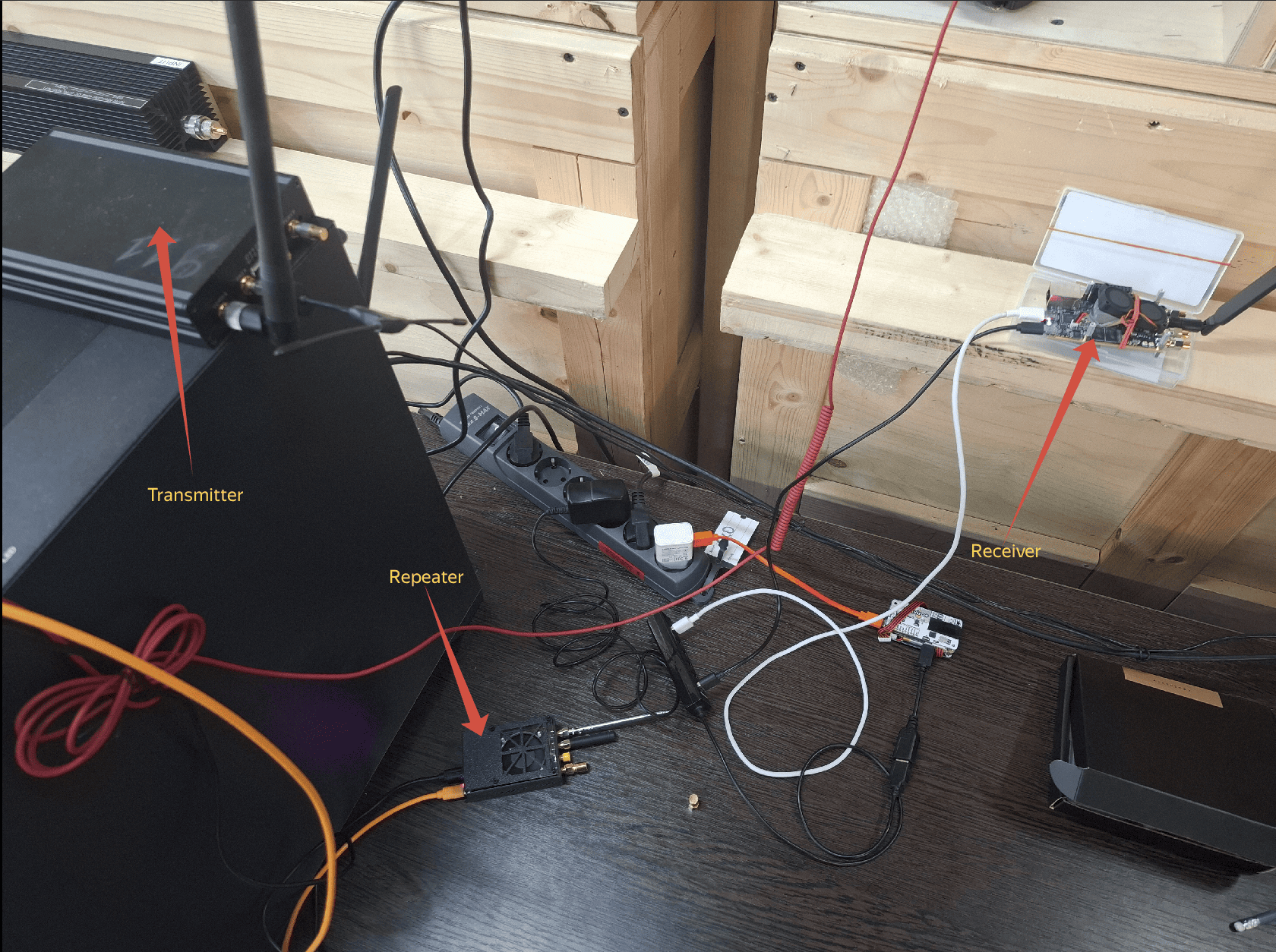
Fig. 9. A simple spontaneous stand for conducting the described experiment
Debugging was performed on 3 SDRs. The transmitter was a USRP B200, and the repeater and receiver were clones of PlutoSDR (and the repeater is based on a chip labeled ad9363, but this does not prevent it from being initialized as ad9361. As in the Analog Devices tutorial, but there in the context of the classic SDR. And this experiment proves that it is possible to do this from under the no‑OS drivers).
The USRP simply transmits a cyclic buffer of 1440 samples, which are a frame with a relay byte. At 10 seconds, you can see how the USRP is initialized in the left terminal and information about the operation of the liquid‑dsp is displayed. At the 11th second, you can see how information is first output to the lower terminal on the right (it is connected to the repeater) and information is immediately output to the terminal on the upper right. This is the receiver terminal. At the 13th second, attention is focused on the upper terminal and the TEST message is highlighted. It is this message that the repeater generates, because Hello, World was generated on the USRP! At the 15th second, TEST is highlighted again in the upper terminal. The fact is that 200 thousand samples with USRP is about 100 frames. Only valid messages are processed. This can be seen in the callback function. In this experiment, when sending exactly 100 frames, at least one valid one was guaranteed to be accepted in 100% of cases. But more often than not, more than one is taken. It is very easy to protect yourself from this by entering frame numbering, but this was not done in this experiment and all valid messages are displayed. At the 17th second, attention is focused on the fact that the initial Hello, World! message was received before the TEST messages. In theory, the receiver is so far away from the source of the message that the receiver simply does not hear the source, otherwise why would we start all this retransmission? Note that HEX is output above the ASCII format. And it's very clear that Hello, World! it was received with bytes 030205. According to our idea, 03 is the source address, 02 is who should relay, and 05 is who this message is addressed to. And when the TEST is accepted, the addresses are already 020105. That is, the repeater also rewrote the addresses. At 22 seconds, pay attention to the lower right terminal of the repeater, it received Hello, World! with addresses 030 205 and nothing else, because there was nothing else on the air and he went on the air himself after accepting 02 in the relay address. He, being a node with the address 02, should relay this message. After that, at 34 seconds, the same thing is sent from the usrp again and the experiment is repeated.
Code for usrp added to github
The most interesting branch is feature/add_bfs. What happens in the video is compiled from this particular branch.
Code for PlutoSDR clones added to github
The code for the repeater from the video is contained in the feature/repeater branch.
Code for the receiver from the video in feature/framingRx.
Code for the transmitter (not used in the video) in feature/framingTx.
Another interesting thread is feature/path_in_the_gpaph. There you can see how the BFS algorithm works without unnecessary code and there are several tests.
To understand at least a little bit what's going on here, it's best to repeat this whole experiment. And in parts, first working only with no‑OS, then add the liquid‑dsp library. Addressing, and only then the breadth-first graph traversal algorithm. If something doesn't work out, then feel free to write comments or in private messages, we will figure it out together.
Thank you.
S.N.
Discussions
Become a Hackaday.io Member
Create an account to leave a comment. Already have an account? Log In.