Samuel A. Falvo II
-
Not forgotten, I promise!
05/31/2017 at 03:47 • 0 commentsI've started employment, and this has been taking up a significant amount of my free cycles. Apologies for slow progress. I'll probably not be able to spend much time on this project for maybe two more months while I continue my on-boarding/training process.
-
Might Switch Back to MISC CPU
05/07/2017 at 16:52 • 3 commentsDon't worry; I still want the RISC-V ISA. But when working with such a tiny FPGA family as the iCE40 line-up, I might have to switch to software-emulation to get what I want.
I was curious today, and synthesized a bunch of cores to see what their resource utilizations are like.
SRAM Interface 130 LUTs Serial Interface Adapter 710 LUTs KCP53000 CPU + 16-bit bus bridges 5500 LUTs S16X4A CPU (Kestrel-2) 510 LUTs If I build out a KCP53000-based computer design, I'll not have any room left on the HX8K FPGA to implement even a tiny boot ROM with. I would need to somehow implement a DMA engine in under 1000 LUTs which simultaneously works with the SIA's quirks as well as serving as an IPL processor for the computer. Not only that, but the computer would have access to exactly one I/O channel.
If I were to somehow expand the S16X4A to 64-bits, dumb expansion and synthesis run gives me a figure of 1500 LUTs. RAM + SIA + S64X CPU is still small enough to let me synthesize an appreciable on-chip ROM for bootstrapping purposes.
Switching to a 64-bit wide variant of the S16X4A CPU and relying on software emulation to provide RISC-V compatibility might be the way forward, at least for these smaller FPGAs.
-
Project Repository Switching Back to Mono-Repo
05/06/2017 at 20:33 • 0 commentsAfter spending an appreciable amount of time working with the Kestrel-3's components in a many-repo configuration (e.g., one for CGIA, one for the CPU, and so forth), I feel that juggling all these different components is more trouble than they're worth.
For this reason, I've decided to (over time) bring all these different components back under one repository. This includes:
- All Kestrel-2 components. This means I'll be discarding the GitHub kestrel2 repository once I bring it back under the mainline kestrel repository.
- The MGIA and GPIA are already in mainline project; but enhancements, such as CGIA, GPIA-2, and my up-coming SIA, currently exist either in ad-hoc locations or in separate repositories.
- The complete KCP53000 family of cores.
While this negatively impacts anyone trying to use open source hardware package managers like FuseSoC, it will make things significantly easier for me as a maintainer, and I think, probably for anyone wishing to contribute back to the project at a later time. If there's enough pressure to repackage components of the Kestrel via FuseSoC or similar tooling, I think the time is well-spent to make these tools mono-repo-aware, rather than having to cater to them.
As a consequence of this, I think the directory layout of the repository will necessarily have to change as well. Cores needn't be tied to specific Kestrel versions, for example, so the S16X4A or MGIA can be reused in other contexts.
I will probably get around to this in the next couple of days, or as I need various cores.
-
SIA Progress: Transmitter and its FIFO Complete
05/06/2017 at 07:08 • 0 commentsSo, after cleaning out the garage, I decided to sit down and work on the SIA core's transmitter logic. I didn't need to do much to make things work; I just re-used my XST (eXpermental Serial Transmitter; no relation to anything from Xilinx) core's transmitter logic, and re-jiggered it to meet SIA's requirements.
I am quite pleased that the SIA is nearly complete. I just need to write the top-level `sia.v` file that binds the receiver and transmitter components together, and I'll finally have a workable, and reusable, UART that plays nicely on Wishbone B.4 bus.
-
SIA Register Set
05/03/2017 at 15:31 • 0 commentsThe Serial Interface Adapter (SIA) core is coming along nicely, if a bit slowly.
I've just implemented the Wishbone slave port for it. It exposes 16 bytes to the programmer, with 16-bit wide registers. Here's the register map for the core (with byte offsets), taken from the Verilog sources as of this posting. Not everything is implemented yet; I still need to finish the transmitter section, for example. Also, SPI features of my XST core aren't exposed and will be removed if not optimized away by synthesis tools. (As you can imagine, this is all quite preliminary still.)
// +0 CONFIG (R/W) // ...........11111 Specifies character frame length, // including start, stop, and parity bits. // ........000..... Undefined. // .......1........ Enable RXC edge sensitivity. // ......1......... Enable RXD edge sensitivity. // ...111.......... TXC mode. // 000 Hardwired 0. // 001 Hardwired 1. // 010 IEEE-1355 Strobe (*) // 011 Undefined. // 100 Idles low; TXD transitions on rising edge. // 101 Idles high; TXD transitions on falling edge. // 110 Idles low; TXD transitions on falling edge.(*) // 111 Idles high; TXD transitions on rising edge.(*) // * - reserved for this purpose, but might not be implemented. // ..1............. RXC edge polarity // 0 Idles low; sensitive on rising edge. // 1 Idles high; sensitive on falling edge. // 00.............. Undefined. // // +2 STATUS (R/O) // ...............1 RX FIFO *not* empty. // ..............1. RX FIFO is full. // .............1.. TX FIFO *is* empty. // ............1... TX FIFO is *not* full. // .00000000000.... Undefined. // 1............... One or more other bits set. // // +4 INTENA (R/W) // ...............1 RX FIFO *not* empty. // ..............1. RX FIFO is full. // .............1.. TX FIFO *is* empty. // ............1... TX FIFO is *not* full. // 000000000000.... Undefined. // // +6 RCVDAT (R/O) // +6 SNDDAT (W/O) // // +8 UNUSED Unused; hardwired 0. // +10 UNUSED Unused; hardwired 0. // // +12 BITRATL Baud rate generator. // +14 BITRATH // 1111111111111111 Lower bits of divisor. // 0000000000001111 Upper bits of divisor. // Bit rate = 100Mbps / (divisor + 1) -
DMA Controller Coming Together
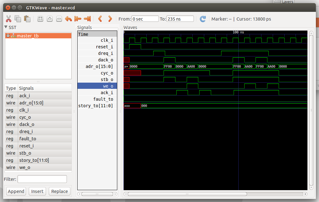
04/29/2017 at 23:56 • 0 commentsI'm working on the DMA controller which will ferry data from the V.4 receiver into RAM. This controller is currently intended for initial-program-load (IPL) purposes, since I don't think I'll have enough resources on the FPGA to implement an appreciably sizeable ROM.
I think it's coming along well so far. Here's a timing diagram courtesy of gtkwave.
![]()
-
Employment Acquired!
04/28/2017 at 15:56 • 3 commentsGood news for the project: I've a new job which I'll be starting in mid-May. I hope to work more regularly on this project starting after mid-July, however, as I'll be on-boarding until then, plus holidays.
-
More Thoughts On Remex: Switch Back to SPI?
04/17/2017 at 03:42 • 0 commentsWhen I first conceived of a computer-with-standardized-I/O-channels architecture for the Kestrel-1, I conceived of using bit-banged SPI ports. Later, when I resurrected the idea for consideration in the Kestrel-3 on icoBoard Gamma board, I tried to map my ideas and desires for talking efficiently to block I/O and to a terminal into a single SPI master/slave interconnect. I wasn't happy with the results, so I later decided that I thought a Spacewire-like interface was the way to go for Kestrel-3 I/O channels. However, I subsequently had some doubts develop over its overall system simplicity as I tried writing the Verilog to make it all happen.
I've decided I'm going to switch back to SPI, at least for now. I'll revisit Spacewire at a later time. I list the reasons why below.
When I first tried to use SPI for an I/O channel, I originally tried two approaches to framing data and enforcing flow control. These approaches were either not flexible enough or required a large amount of resources on the slave device to implement. I've since devised a third solution which, I think, neatly solves the problem. It seems quite economical to implement, and it definitely has some advantages over Spacewire (and, interestingly, Ethernet).
The first approach I took used the SPI slave-select signal as a framing delimiter. When asserted, the slave controller knew a fresh packet of data to interpret was on its way. When negated, it could return to a quiescent state. This works great for master-to-slave communications. The reverse data path is not well supported, however. It requires a dedicated (and non-standard) service-request signal, which functions not unlike an interrupt pin on more traditional backplane buses. When service-request is asserted, the host knows the slave needs to communicate with the host. This communication path must still be conducted using a master/slave protocol exchange of some kind, but at least the host can get away without having to poll the device all the time. Another problem with this solution is that it requires at least five digital I/O pins to implement, preventing it from being used on a 1x6 PMOD port.
The second approach I took discarded the slave-select signal all-together, leaving only MOSI, MISO, and CLK signals. The master/slave relationship continued to exist (only the master can drive CLK). But, I observed that the link was strictly point to point, so the slave-select signal had very limited utility. In its place, I decided to frame data using HDLC, PPP, or COBS. If the slave indicated that it wanted to operate asynchronously, the master would need to drive CLK continuously, allowing the slave to send data when it deemed appropriate. Otherwise, the CLK would be driven only until the number of responses balanced the number of outstanding requests. In either case, both directions used the same framing protocol. The problem with this approach is basic flow control. How big can the frames be? If I use an ESP8266, they can be quite sizeable. If I use a ATtiny microcontroller, not so much! How to implement flow control? I'd need to follow HDLC-like RR/RNR-style flow control, which operates on a packet-by-packet basis. That means I'd need enough buffer space to support at least 7 outstanding frames, which I'd then have to arbitrarily limit to, say, 256 bytes each. So, estimated, a microcontroller would need about 2KB minimum space to support this interconnect technology, not counting driver overhead, and of course, the intended application of the controller in the first place.
The solution, it seems, is to isolate the flow control mechanism from the delivery of individual bytes and framing. Each direction of the channel operates independently, and in one of two modes of operation. When the link is first established, each direction defaults to "flow control mode". In this mode of operation, bytes take on a special significance: bits 5:3 contains the number of 8-byte words which follows, while bits 2:0 contains the number of 8-byte words the receiver can reliably take on. (Bits 7:6 haven't been defined; assume they do nothing for now.)
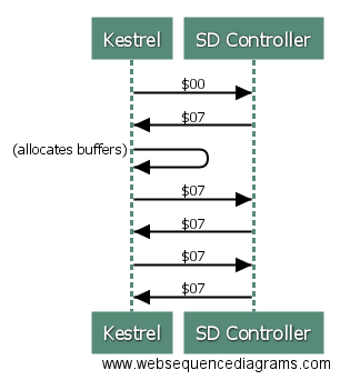
7 6 5 4 3 2 1 0 0 0 DATA2 DATA1 DATA0 CREDIT2 CREDIT1 CREDIT0 Let's make this concrete. Pretend a Kestrel is trying to establish a connection with a block storage device (say, a SD card driver). The Kestrel first tries to send $00 down the link. The SD card controller sees this and knows right away that the Kestrel does NOT have any available buffers to receive data with (bits 2:0 are 0). Thus, it cannot send data back to the Kestrel even if it wanted to. It also knows that the Kestrel is not intending on sending data right now (bits 5:3 are also 0).
At the same time as it's busy receiving that initial $00, being an SPI link, the SD card driver sends out $07. The Kestrel will receive this byte, and discern two things: first, that the SD card device is not intending to send data, and that the SD driver has 7 8-byte words available for its receive buffer. This means that the Kestrel can, if it needs to, send up to 56 bytes of data to the SD driver at some later time.
This process continues as long and as frequently as necessary. If/when the Kestrel opens up a buffer to receive data with, it obviously adjusts its flow control word accordingly. Eventually, both ends might end up sending $07 to each other.
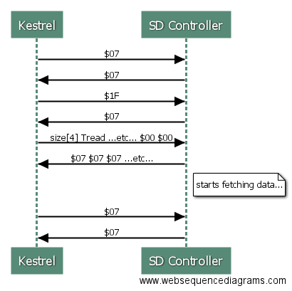
When the Kestrel does desire to send a command to the SD controller, it communicates this fact via a flow control byte. A 9P packet for TRead consumes 22 bytes, which after COBS encoding will consume 23 bytes. This means we need to send 3 8-byte blocks down the line, so the Kestrel issues $1F. This means the computer has 3 8-byte units to send as normal data, and still has 56 bytes of buffer space available. Immediately following this flow control byte, the Kestrel sends the 9P TRead request, filling unused bytes with zeroes. As this is happening, the SD controller continues to respond with $07 bytes.After sending the 24 bytes of "normal" data, the Kestrel-to-SD-controller direction of the link immediately reverts back to flow control mode. This means, while it's waiting for a response from the SD controller, it's sending out $07 or some similarly relevant flow control byte.![]()
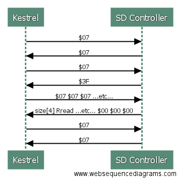
The SD controller, after reading the required data, needs to send data back to the Kestrel. Since (thanks to the last flow control byte it received) it knows the Kestrel has a 56-byte buffer available, it can send data using the largest chunk of normal data possible. So, it sends the flow control byte $3F (bits 5:3 indicate a 56 byte block of data follows, while bits 2:0 indicates a full set of 56 bytes available for receiving). It does this for as long as it has data to send. Assuming it's reading a 1024-byte chunk of data from a file, the Kestrel can expect to see $3F bytes interstitially with 56-byte blocks of data at least 18 times.![]()
After the request has completed, the Kestrel may stop the clock to save power. Since we only need MOSI, CLK, and MISO for this solution to work, we have a pin free for service request in case the SD controller to sends a frame asynchronously to the Kestrel (e.g., card inserted or removed event).![]()
Now, you might think this is not terribly efficient use of available bandwidth. Hold on to your horses, because this is going to surprise you. Ethernet frames, completely ignoring physical level signaling overheads, gets best efficiency at 1500 payload bytes (obviously). It has a fixed 36 bytes of framing overhead, so this translates to 2.4% frame overhead. However, the mechanism I described above requires only 1 byte every 56, for a best-case of 1.75% overhead. Remember that Ethernet additionally requires Manchester encoding for 10Mbps, 8b/10b-encoding for 100Mbps, and 64b/66b-encoding for GigE and higher which imposes an additional 100%, 20%, and 3% overhead on top of the 2.4% from framing. This means Remex can actually be more efficient at sending large blocks of data than Ethernet. (Assuming no jumbo-frames, which in practice, aren't used frequently except in backbone links anyway.)
-
SRAM Read/Write Tests Successful!
04/11/2017 at 21:50 • 0 commentsI made a quick and dirty circuit to exercise RAM reads and writes. The idea is simple: ramp through a counter. Bits 0..3, 5..20 (a total of 20 bits) routes to the address pins of the icoBoard Gamma's SRAM chip. Bit 4 is used to select read/write. This way, the RAM alternates between reads and writes. Data input is taken from the current address bus, while the data output pins drive LEDs directly, with NO intervening processing.
Test 1 - Cold start - Random data is shown on the LEDs.
Test 2 - After running test 1 for a while and resetting the board, the values read back appear to correspond to the current address.
In short, RAM is accepting data, and is reporting the same data back.
I ecstatic. After many months of failure after failure with other FPGA boards, I'm just so happy that this is working. You have *no* idea.
The next step is to work on completing a serial I/O interface to talk to the outside world with. I might interface a S16X4 as a test CPU before trying the RISC-V. Not sure yet.
-
icoBoard Gamma Back in Business
03/29/2017 at 16:18 • 1 commentYesterday, I decided to breakdown and acquire my first Raspberry Pi computer. I got a RPi 3 and, I must admit, it is a nifty little device. Accolades aside, though, this platform was the original way to program icoBoard FPGA boards, and thought since I cannot raise icoBoard Gamma on any of my Linux OR Windows laptops, I'll try the RPi route. It's cheap enough, so why not?
Immediate success. Not only have I never seen an FPGA program in about a quarter of a second before, but the whole arrangement worked out-of-the-box (except for one brain-fart on my part: if you've attempted to install icoprog for USBaseboard before, be sure to remove those binaries from your path so that the icotools makefiles correctly detect the right way to program the board). Seriously: if you can imagine this as the FPGA world's "MacOS" (where things "just work"), this is it.
Does this mean Kestrel-3 development is back on track? Not quite; I still need to gain employment, and my energy is still focused on that. But, at least I have a working FPGA board again, and I hope one in which I can reliably talk to RAM with.
Kestrel Computer Project
The Kestrel project is all about freedom of computing and the freedom of learning using a completely open hardware and software design.