Close
0%
0%

CircuitPython Badge

A handheld running CircuitPython and cheap enough for a badge.

Similar projects worth following

More and more conferences want to have a cool badge. But most badges are not really that interesting or useful. Sure, you can learn soldering if you have to assemble it yourself — but then most people never do. You can play tetris during boring talks, or, if you really don't want to attend any talks, you can spend time programming it in some exotic assembly to play snake. And as soon as you get home, it goes into a drawer to never see the light of day again.

But we can do better than that!

We can make a badge that is useful during the conference — that has USB disk storage where you can put conference materials, slides of all talks, etc. It can display the schedule, and maybe even have reminders for the talks you wanted to see. It can have some simple games for the boring talks, but also perhaps some social games, to make you talk to other people. But most importantly of all, it can be super-easy to program, without having to install anything on your computer or learn some esoteric language — by simply copying Python files on it. And finally, when you get home from the conference, you can incorporate it into other projects.

This project is not about a badge for any particular conference. It's about making a baseline project, that can be then taken and extended/modified for a particular conference. The idea is that it should be easier to make something actually useful, instead of a gadget with blinking LEDs.

  • Sketching the Next Version

    deʃhipu10/02/2018 at 13:59 0 comments

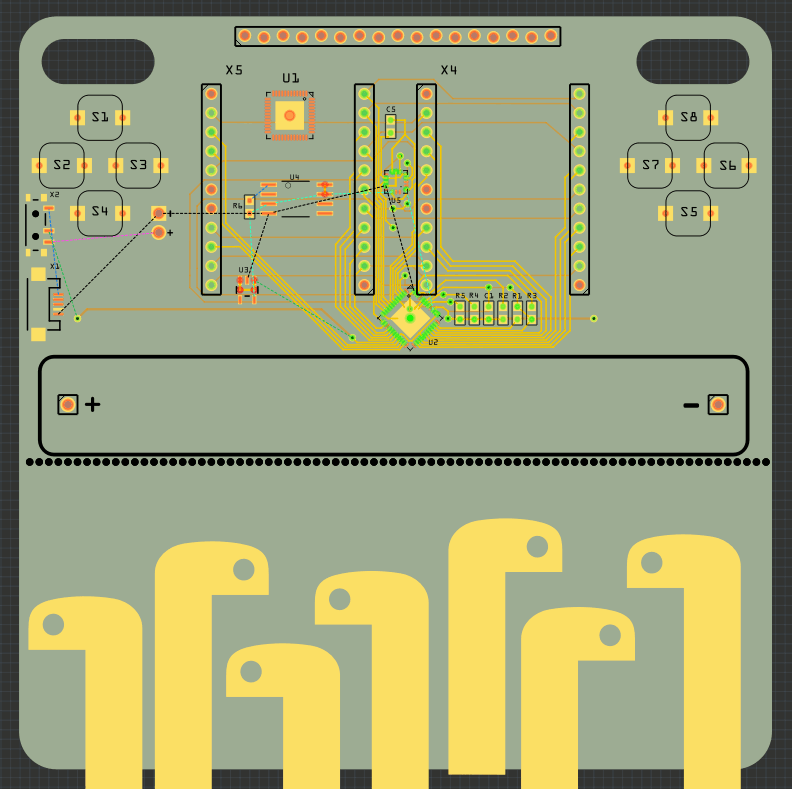
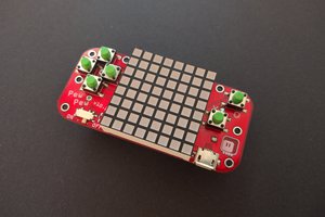
    Together with the volunteers we already started working on the next version of the prototype. I started to slowly lay out the components for it:

    Several things are happening there:

    • switched to a SAMD51 microcontroller, in place of the smaller SAMD21 — that gives us more memory, better speed and more pins,
    • moved the electronics under the display, to make more room on the sides,
    • switched to non-clicky buttons, same as I used in #µGame,
    • got rid of the snake heads at the top, to make more room,
    • added a pin header for connecting extra stuff to GPIO pins,
    • considering using a different USB port, though I don't have a footprint for it yet,
    • considering using IR communication in place of the NRF24, but that requires some experiments,
    • considering moving the batteries from the back to the front, to make the whole thing more flat.

    This is all just playing for now, to see how it fits together. We will probably still make a lot of changes.

  • Prototypes in Good Hands

    deʃhipu10/01/2018 at 09:32 0 comments

    It took some logistic trickery, but we got five prototypes of the badge into hands of willing and skilled people, who will now test and improve the hardware, software and documentation. There is a repository at https://github.com/circuitpython-badge/circuitpython-badge containing what was produced during the sprints at PyCon.UK, and some discussions in the issues section. After the initial prototype design we can now hopefully take it to the next step, to make it fit the needs of the conference participants.

  • Testing Prototypes and Possible Optimizations

    deʃhipu07/16/2018 at 20:18 0 comments

    I have five prototypes assembled and tested, and I'm going to take them next week to Europython to Edinburgh and pass them on for testing. We decided to skip this year and I'm for next year, which will give us more time to develop the libraries and examples for them.

    In the mean time, as I'm working on the #PewPew Standalone, I'm getting ideas about how to reduce the parts count and price of those badges. Since I'm using two 7×11 matrices, I can drive them with just 18 pins by using a kind of charlieplexing approach — that means that a bigger SAMD21 chip should be able drive them all, and still have spare pins for breaking out. That could shave off as much as ¼ of the cost. Of course the cost of that would be scanning the matrix in software, but I already have to write the library for this for the PewPew.

    I also still need to get the radio going. There are ready NRF24 libraries, but I think we will want to have something custom more similar to Micro:bit's "radio" library.

  • Full Badge Assembled and Working

    deʃhipu05/31/2018 at 18:16 0 comments

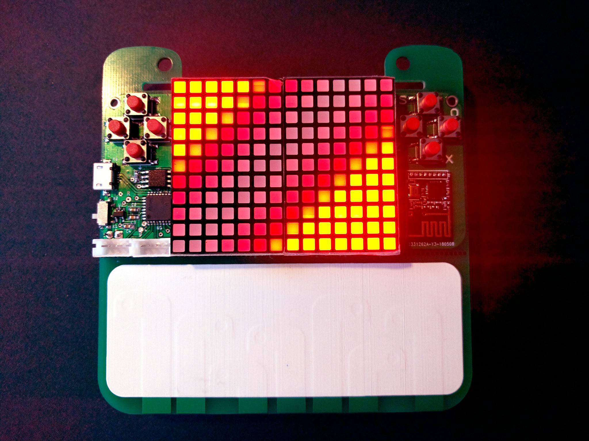
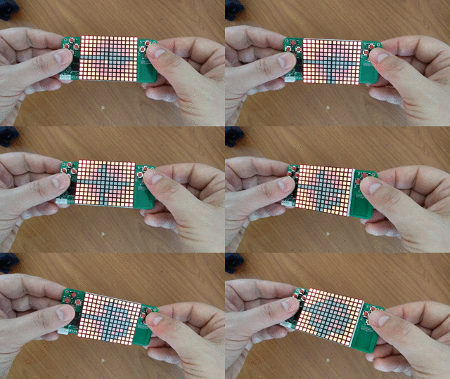
    I finally had some time to sit down and assemble the badge. The accelerometer chips still didn't arrive, but I just desoldered one from some breakout board I found in my drawer. As usual, the QFN matrix controller chip didn't get soldered properly, and I had to desolder the matrices, fix the chip, and re-solder them back. Some traces got pulled in the process, but fortunately for unused pins of the matrices, so it's fine.

    Of course my camera can't handle the brightness of the LEDs, so instead of red they appear yellow.

  • Full PCB

    deʃhipu05/25/2018 at 09:09 0 comments

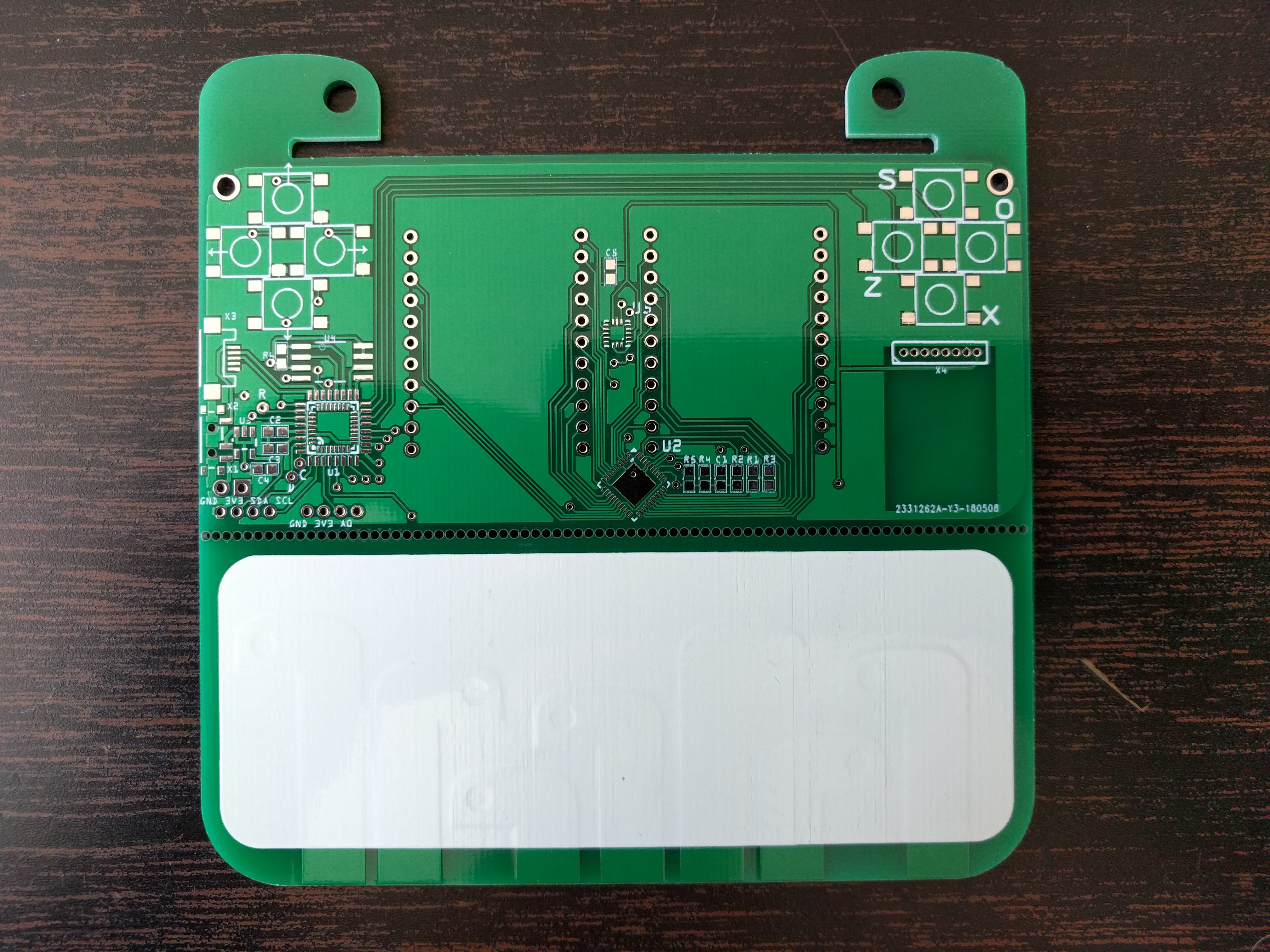
    Of course the PCBs arrived just as I'm leaving for the Belgrade conference, so no chance to assemble one and use there as a badge. Oh well, I think I will wear an unpopulated PCB anyways.

    As I was afraid, the large white area of the silkscreen doesn't look too great. I think that I will use a white PCB and just a black outline next time.

  • Full Size

    deʃhipu05/07/2018 at 20:20 0 comments

    Since I'm more or less happy with the design now (after a few inevitable corrections), I decided to design and order a full badge now. It looks something like this:

    There are python snakes on the copper layer under the large white rectangle — but you can't see them, since they are covered. I think they will still be visible in reality, due to their relief. The bottom half can be broken off — when you want to use this for something else after the conference ends.

  • Repository and Schematic

    deʃhipu05/06/2018 at 21:47 0 comments

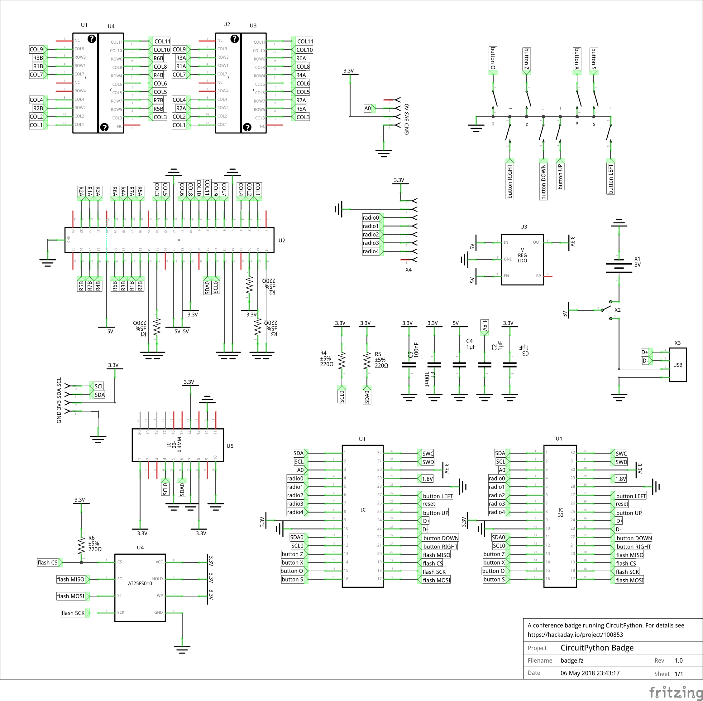
    I spent some time cleaning up the schematic — fixing the custom part graphics, adding net labels and arranging it in a way that hopefully makes it a bit easier to read. In the proces I noticed that I didn't connect the ground of the buttons on the right side to the ground — another bodge wire needed. Also, all the values for resistors and capacitors are still wrong — I will need to change them.

    I also put all the design files and code into a repository, for everybody to enjoy. Please be aware that it is still work in progress and that there most likely will be changes.

  • Accelerometer

    deʃhipu05/06/2018 at 11:53 0 comments

    Today I added a few functions to the library to get access to the accelerometer:

    For now it's very simple, you just get the x, y and z acceleration values, but that should be enough to write some cool demos.

  • Battery Life

    deʃhipu05/05/2018 at 18:38 0 comments

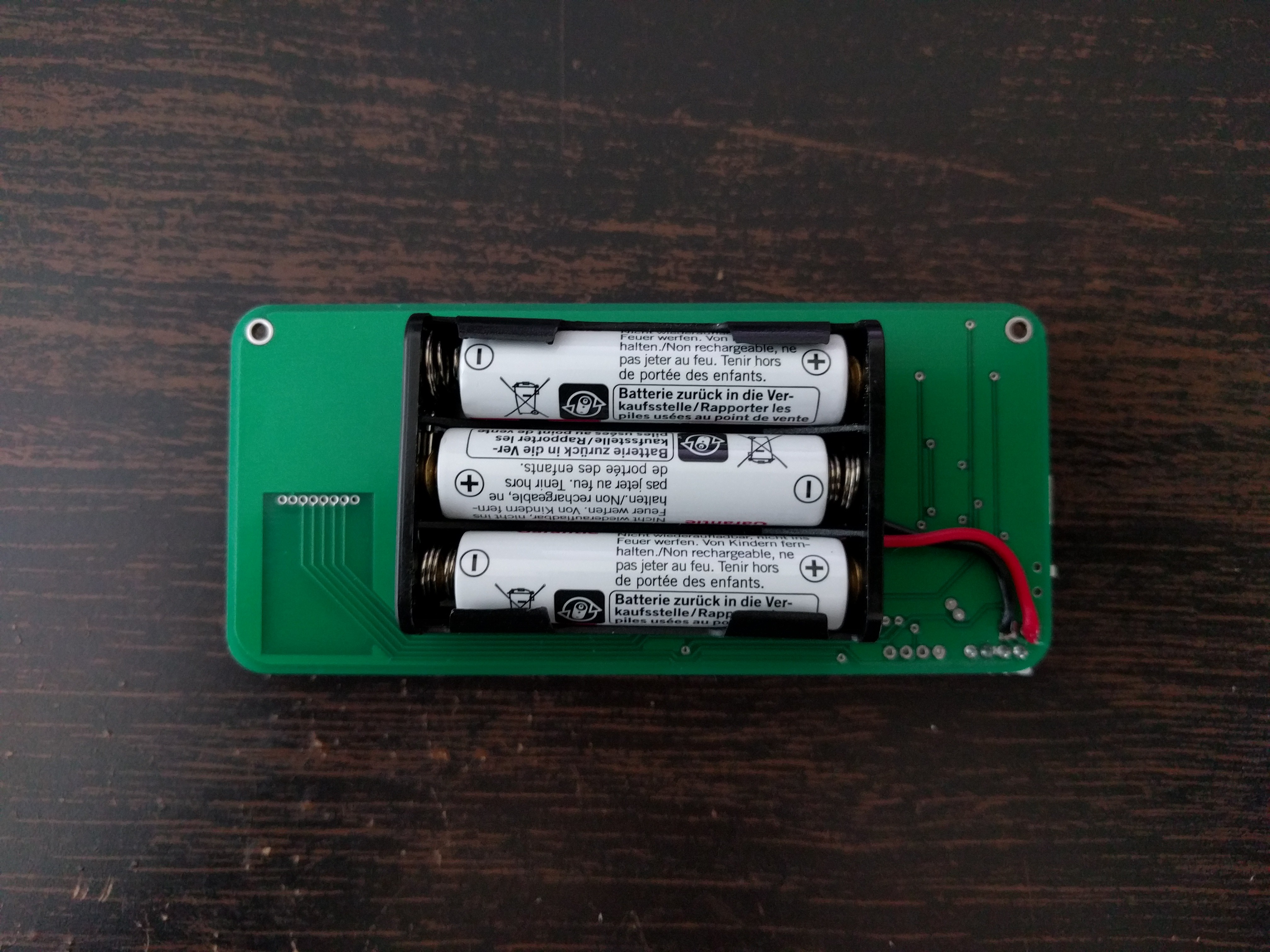
    One of the most important features of a conference badge is that it has to last through the conference. Which is not that easy, if you also consider that its display has to be visible from a distance in full sun, and that you can't use rechargeable lithium batteries. So I put the prototype badge to a test. I'm using 3 alkaline AAA-sized batteries, and I'm displaying a simple pattern of light and dark pixels, that hopefully somehow reflects what will be displayed on those badges, at least on average. It's also set to 50% overall brightness, which is currently the default setting, as it is bright enough to be visible in daylight.

    I'm using a local brand "no name" batteries, because that's likely what a conference will also use, and it's probably the lowest quality I can easily get without ordering from China.

    At the 9 hour mark I had a small problem: the tablet I used to run the stopwatch application ran out of battery itself — I forgot to connect it to a charger. But since I made a photo at the beginning of the experiment, I easily fished the start time from the EXIF data, and still can tell the exact time.

    It's been 11 hours now, and the badge is still working. The voltage dropped from the initial 4.5V to 3.7V at the 4 hour mark, and to 3.6V at the 9 hour mark. At 11 hours it's at 3.5V. In theory, the badge should work down to 2.8V, so I'm really hopeful for this breaking the 12h mark.

  • QFN48: Welcome to Hell

    deʃhipu05/01/2018 at 11:56 0 comments

    Turns out the hot air gun helps, but not nearly as much as I hoped. And putting other parts on top of your part, to make the rework impossible certainly doesn't help. Long story short, I had to desolder both matrices (suction tool helped a lot), and rework the chip. When assembling it back, I decided I don't need the sleek look for now, and instead I would like ease of debugging, so instead of matrices I soldered female headers that I can plug them into:

    Read more »

View all 28 project logs

Enjoy this project?

Share

Discussions

Makerfabs wrote 05/10/2018 at 06:22 point

snake game with the Accelerometer :)   

some USB connector that have THT positioning column would be help to avoid the USB connector tilt.

  Are you sure? yes | no

RoGeorge wrote 04/15/2018 at 12:31 point

Can't take my eyes off of that pic, no idea why.
:o)

https://cdn.hackaday.io/images/5575541523658106909.jpg

  Are you sure? yes | no

deʃhipu wrote 04/15/2018 at 13:18 point

Yeah, pretty shiny lights. I think it's going to look great on a badge, with people programming some cool animations, like flames or plasma.

  Are you sure? yes | no

davedarko wrote 03/25/2018 at 13:26 point

hmm, what happened to the usb port?

  Are you sure? yes | no

deʃhipu wrote 03/25/2018 at 14:56 point

Too much rosin. This is just a mockup with the parts I had lying around. The real PCB is already ordered, should come in a dew days, then I can assemble it properly.

  Are you sure? yes | no

Similar Projects

Does this project spark your interest?

Become a member to follow this project and never miss any updates