 Michel Kuenemann
 few words about our champion:
- System:
- ARM Cortex-M0+ processor, running at frequencies of up to 30 MHz with single-cycle multiplier and fast single-cycle I/O port
- ARM Cortex-M0+ built-in Nested Vectored Interrupt Controller (NVIC)
- System tick timer
- Serial Wire Debug (SWD) and JTAG boundary scan modes supported
- Micro Trace Buffer (MTB) supported
- Memory:
- 16 kB on-chip flash programming memory
- 4 kB SRAM
- Boot ROM API support:
- Boot loader
- USART drivers
- I²C drivers
- Power profiles
- Flash In-Application Programming (IAP) and In-System Programming (ISP)
- Digital peripherals:
- High-speed GPIO interface connected to the ARM Cortex-M0+ IO bus with 14 General Purpose I/O (GPIO) pins with configurable pull-up/pull-down resistors
- GPIO interrupt generation capability with boolean pattern-matching feature on eight GPIO inputs
- Switch matrix for flexible configuration of each I/O pin function
- State Configurable Timer (SCT) with input and output functions (including capture and match) assigned to pins through the switch matrix
- Multiple-channel multi-rate timer for repetitive interrupt generation at up to four programmable, fixed rates
- Self Wake-up Timer (WKT) clocked from either the IRC or a low-power, low-frequency internal oscillator
- CRC engine
- Windowed Watchdog timer
- Analog peripherals:
- Comparator with external voltage reference with pin functions assigned or enabled through the switch matrix
- Serial interfaces:
- Three USART interfaces with pin functions assigned through the switch matrix
- Two SPI controllers with pin functions assigned through the switch matrix
- One I²C-bus interface with pin functions assigned through the switch matrix
- Clock generation:
- 12 MHz internal RC oscillator trimmed to 1 % accuracy that can optionally be used as a system clock
- Crystal oscillator with an operating range of 1 MHz to 25 MHz
- Programmable watchdog oscillator with a frequency range of 9.4 kHz to 2.3 MHz
- 10 kHz low-power oscillator for the WKT
- PLL allows CPU operation up to the maximum CPU rate without the need for a high-frequency crystal. May be run from the system oscillator, the external clock input CLKIN, or the internal RC oscillator
- Clock output function with divider that can reflect the crystal oscillator, the main clock, the IRC, or the watchdog oscillator
- Power control:
- Integrated PMU (Power Management Unit) to minimize power consumption
- Reduced power modes: Sleep mode, Deep-sleep mode, Power-down mode, and Deep power-down mode
- Power-On Reset (POR)
- Brownout detect
- Unique device serial number for identification
- Single power supply
- Operating temperature range -40 °C to 105 °C
- Available as XSON16 package
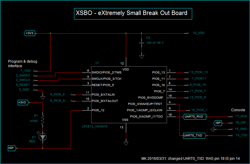
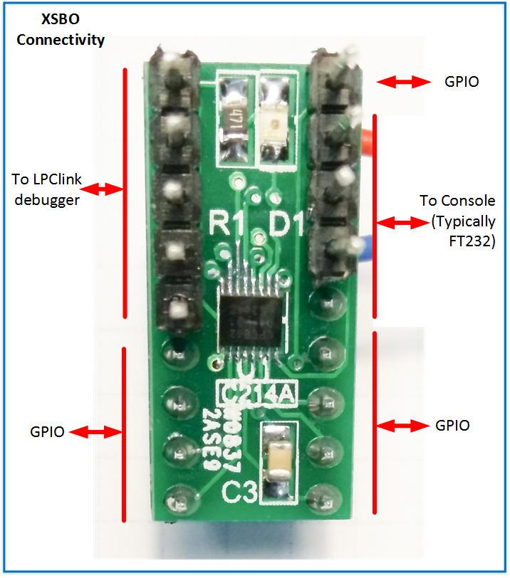
Board Schematic
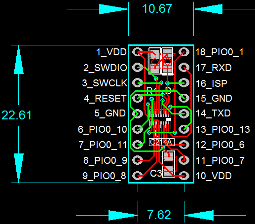
Board Pinout (Top View)
The pitch of the pins is 2.54 mm (100 mill).


 Tirdad sadri nejad
 Ben Lim
 IoT-devices, LLC
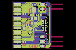
Hi Michel, really nice and tiny project in the similar climate like mine :)
https://hackaday.io/project/10412-awesome-pcb-breakout-board-for-most-popular-smd
Cheer Simon.