David Brown
-
Stepper controller - v2.0
04/18/2016 at 21:06 • 1 commentRunning a test with EasyDriver stepper controllers coupled with L298N H-bridge units has shown that this is not the best solution. Principally as it provides no current control when operating larger motors through the L298N units. And burn up significant amounts of power as heat, in both motor and driver.
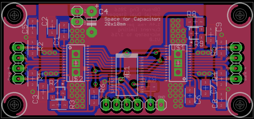
To this end i've found the DRV8880 stepper controller that is capable of 2A (1.4A rms) per phase, and that has current control, the ability to control the torque, and as a bonus 1/16th resolution. I've put together a board using a pair of drivers with an MCP23S17SS SPI I/O expander.
![]()
In order to utilise this with my rPiZero a new version of the breakout board is needed that frees up the SPI lines. The resulting board is half the size as the previous version, as it does not need space for the EasyDriver units. The new rPiZero board also incorporates an EEPROM to store the settings data for the I/O pins. As per the Raspberry Pi HAT standard.
![]()
-
Print head boards build up
04/18/2016 at 19:35 • 0 commentsThe prototype PCBs for the print head arrived, and were duly populated; so the process of working out where I made the mandatory mistake on each of them was! so;
Lower board needed one pull up and one pull down on the FIFO, not a problem, as I had put in test points to allow for this.
The upper board I had followed the pinout/spec sheet for the Arduino Nano 2.3 which had the A0-A7 pins in the reverse order to the current v3.0, not such a huge problem, but meant the I2C lines were in the wrong location. The DC-DC board was also not playing, and as I've decided to use 12v rather than 24v for the mirror motor (what i've used for testing) it needs replacing as he minimum was 18V input (an expensive mistake, but the converter unit should come in handy in the future).
Cue the micro red fixing wire, and Stanley knife for track cutting
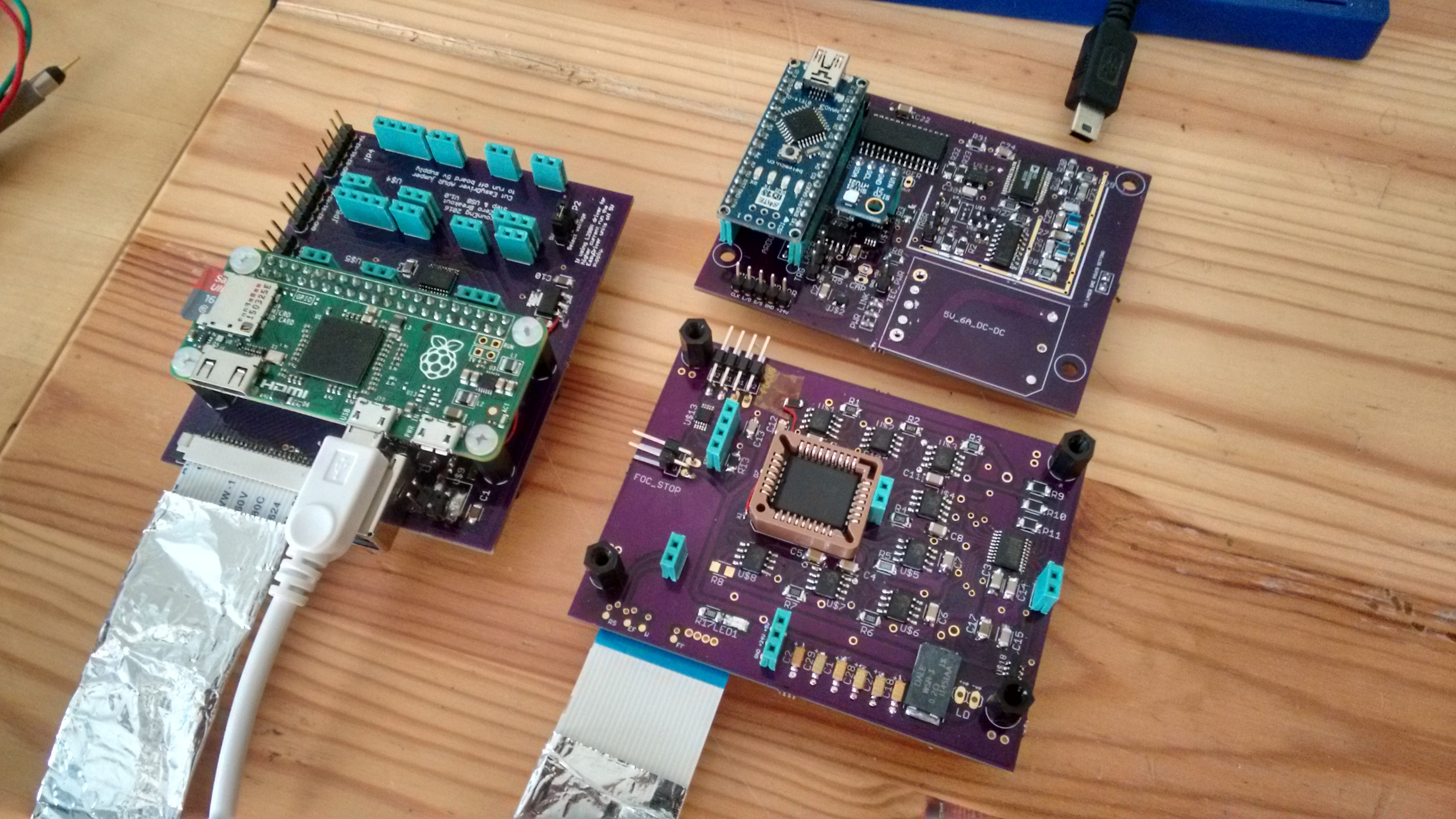
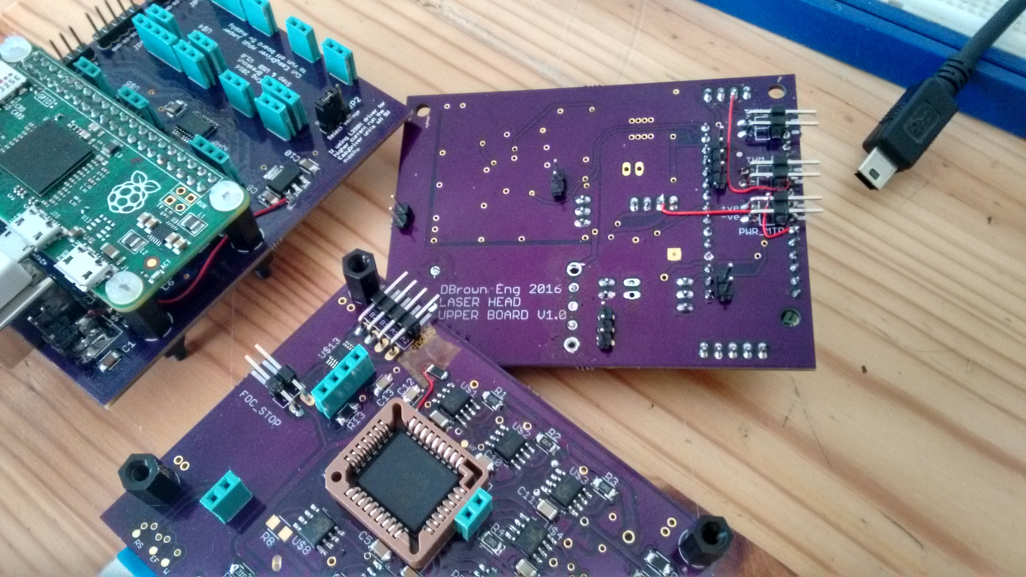
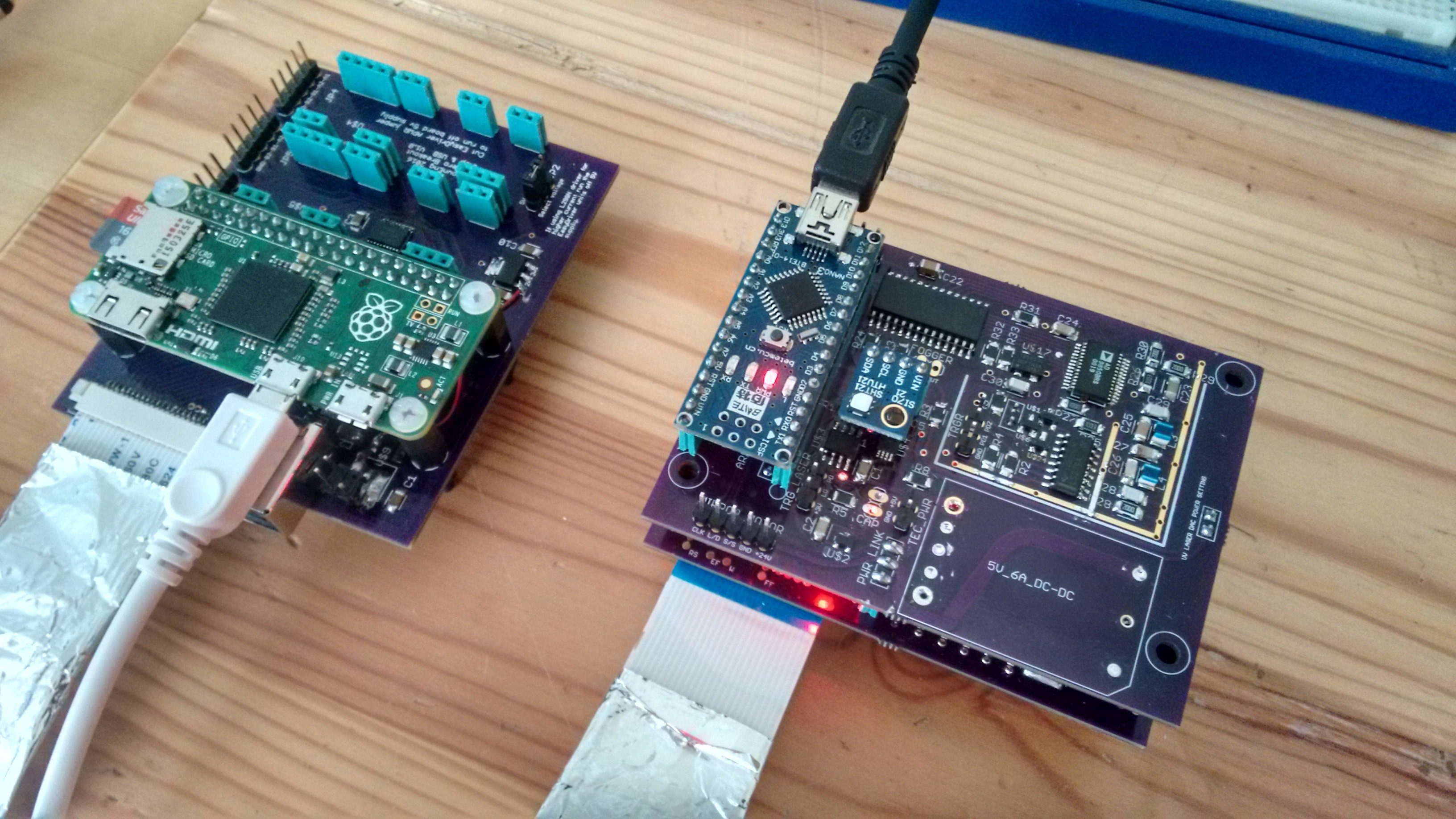
![]() Upper head board has the I/O headers for TEC, trigger laser, mirror motor controls and variable frequency generator for the FIFO readout clock. This last is to ensure a hardware based readout system for the FIFO to ensure that laser strip aligns (within 1 clock wavelength) with the adjacent one.
Upper head board has the I/O headers for TEC, trigger laser, mirror motor controls and variable frequency generator for the FIFO readout clock. This last is to ensure a hardware based readout system for the FIFO to ensure that laser strip aligns (within 1 clock wavelength) with the adjacent one.As can be seen the arduino is back feeding power to the lower board when on USB connection, not ideal situation, blocking diode to be grafted in. Similarly for the data lines of the FIFO when the rPiZero is connected - not something I expected to happen.
![]()
Pi board and upper & lower laser head boards, including x8 iC-HKB laser diode switches with power tuning DAC and current monitoring ADC. The focus system micro stepper motor driver is on the upper left corner of the lower board.
The x8 separate laser switches are needed because the current control is set by a resistor and tuning voltage, which it is not feasible to modulate a single unit to achieve spike free operation, with 8bit resolution. With the present setup each current level can be tuned via the x8 DAC using both a power photodiode and current monitoring ADC, prior to the print process.
![]()
Re-wired I2C lines, with the devices now reporting as expected on the bus.
-
Clocking out FIFO & fake parts
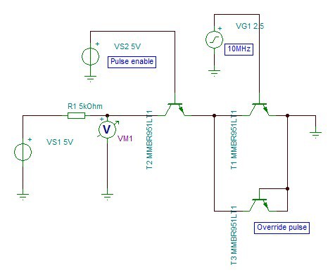
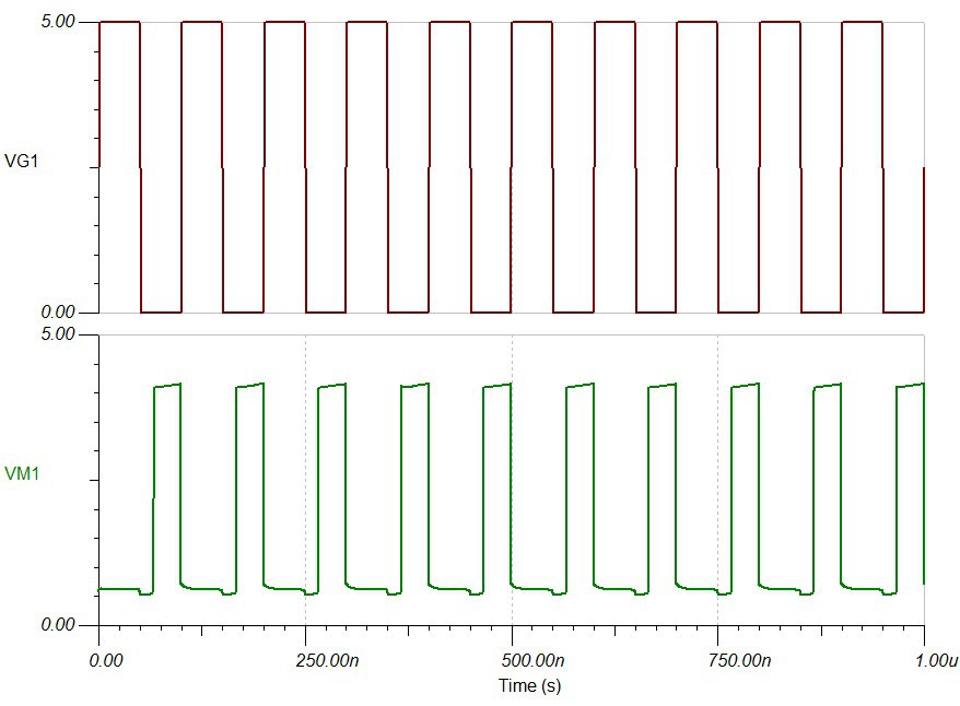
04/06/2016 at 21:20 • 3 commentsFor the current laser power I need a clock out frequency of 2MHz, but i've run a test using TINA simulation software at 10MHz, the transient analysis look reasonable (to my untrained eyes.
I've also been running some test on the write out speed from the raspberry pi, which is looking reasonable through the 600mm ribbon cable. I need a data rate of 500kHz (2us) pulse width.
In other news the IDT FIFO chips i bought off ebay appear to be fakes, they appear to work, but response speed is dire and they are missing the IDT logo, which should have been a big red flag, but I bought them right at the beginning, so another learning experience.
[Followup - ran a full test on the dodgy chips, write depth of 8192 matches but the read out flag is non-responsive, they have also been over-coated, see here for many good examples; Components Technology Institute counterfit examples]
![]()
![]()
-
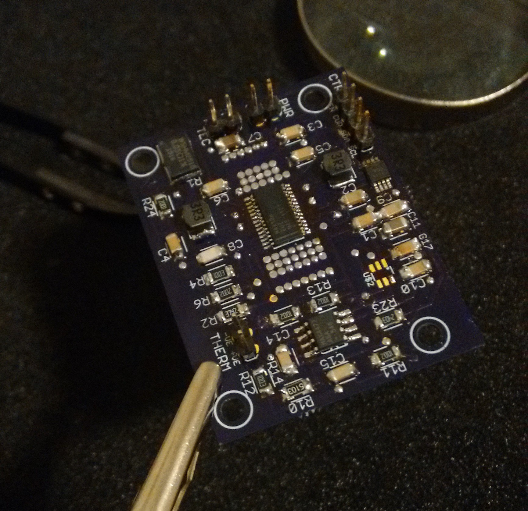
TEC controller - populating
04/05/2016 at 01:02 • 0 commentsPopulated the majority of the TEC controller board, still waiting on an op-amp that is on back order, but I should be able to test the DAC that controls the temperature set point. Very pleased with this board even if the circuit is 98% the one for the evaluation kit, the layout is 100% my own. Will find out in due course if it works.
![]()
-
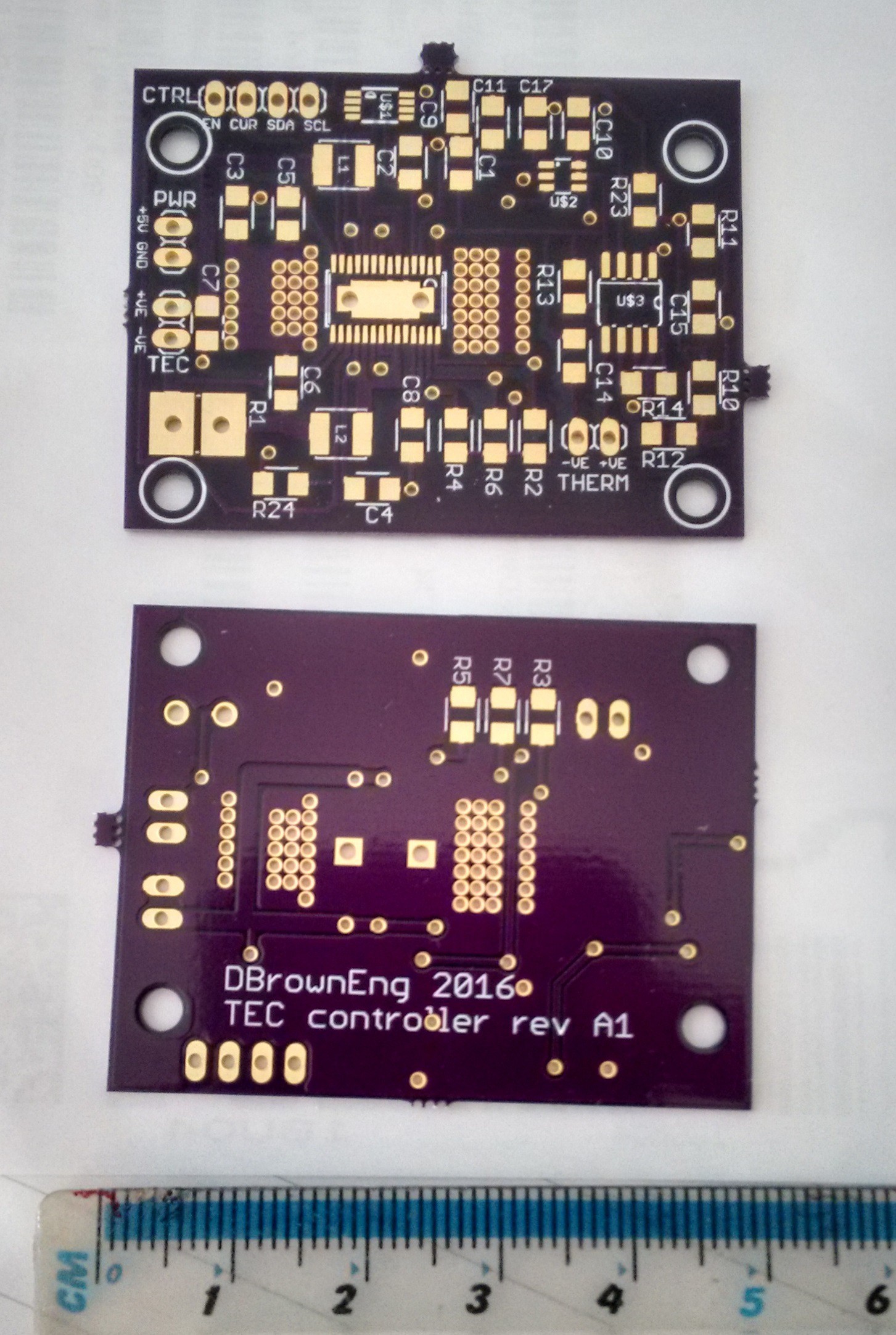
TEC controller
04/03/2016 at 19:25 • 0 commentsThe TEC controller boards arrived from OSH and I've sent the order for the upper and lower boards for the print head, so I should have those in a few weeks.
This board is essentially the same circuit as that in the MAX1968 evaluation kit, and I've made the component numbers the same where applicable. I'm using the MAX5215 DAC (I2C) for setting the required temperature once I know it is working correctly I'll make the boards available on OSH.
Most of the components are on their way from mouser, but one of the op-amps is on back order, and I'm waiting for the TECs to come from China, so it will be a while before I know if the board is correct.
![]()
I was hoping to source a TEC locally, but the ones I'm after have a large surcharge for small orders, so have ordered a couple of 3V TECs from china/ebay. This has necessitated a re-design of the laser head to accommodate the slightly larger (20mm rather than 14mm) units.
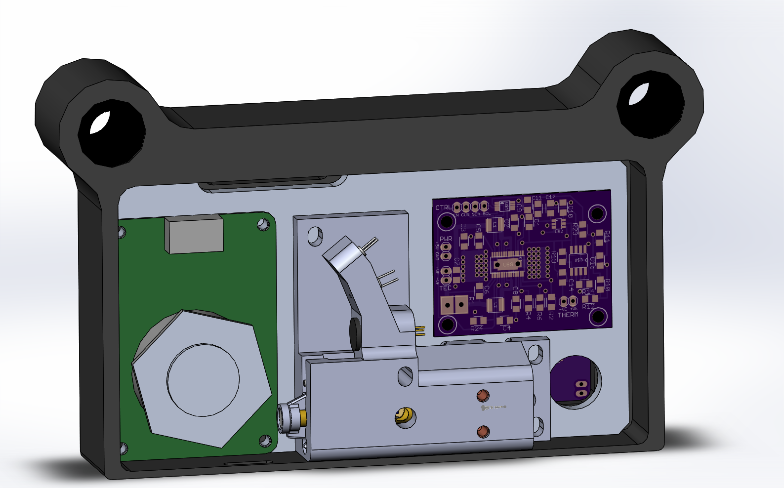
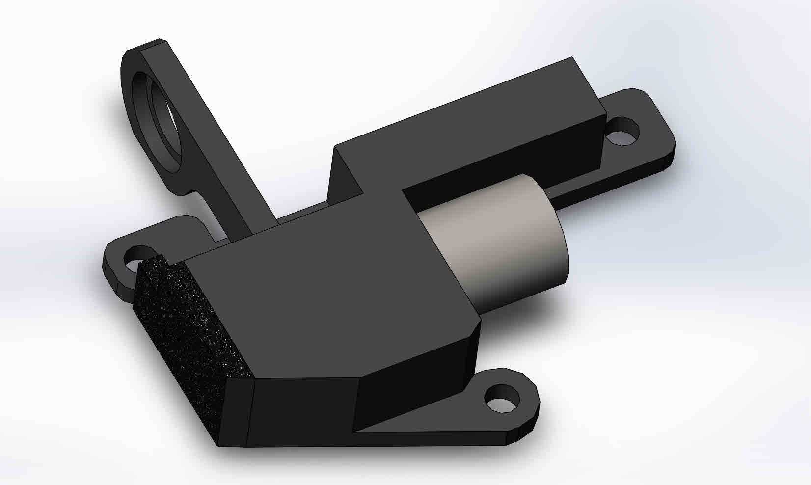
The laser block/head will be 3D printed and integrates the UV laser, heat-sink block, TEC, collimating lens, focus system, laser power sensor and trigger system into one part that can then be positioned in relation to the polygon mirror.
![]()
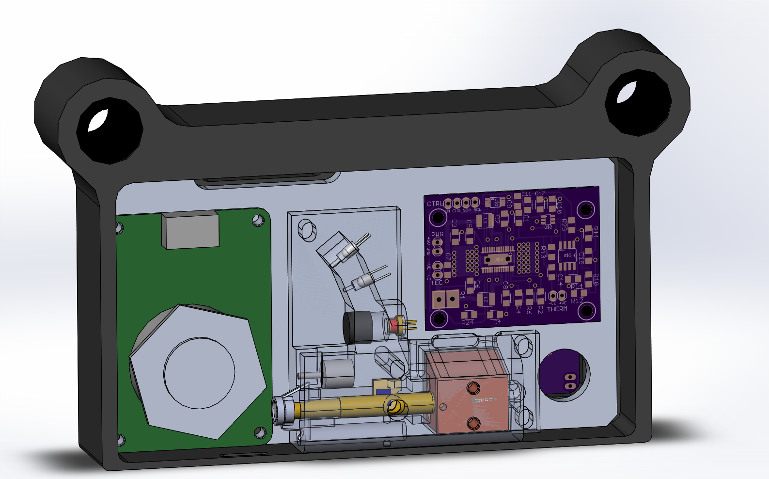
Fig - print head, laser head, mirror unit & TEC board
Fig - laser head internal components.![]()
Having the trigger and UV lasers moulded in one part ensures that the design angles are maintained. The focus system consists of telescoping brass tubes moved by a spring and micro stepper motor.
In other news my L298N boards are stuck in postal limbo, so I've still not had the stepper motors turning, but as I've already tested the outputs, that's not an issue.
I'll do a separate update for the programming part of the serial link between the Pi and the Arduino.
To Do;
- get polygon mirror running under Arduino control
- design focus limit switch arrangement
- get basic link between Pi and Arduino working
- assemble TEC board
- continue setting up basic Arduino commands to be called from the Pi, to allow the greatest flexibility in control, testing and set-up for the print head. When printing the Arduino will be in a static condition and not required to perform any functions. It is solely for setup / calibration and intermittent monitoring during head move.
- continue hardware design of kinematic systems
-
Board testing
03/26/2016 at 00:05 • 0 commentsStill waiting on the stepper L298N PCBs but the Raspberry Pi Zero breakout board is behaving correctly; enabling the voltage level converters and signals through to the EasyDriver units.
One area that I've revisited on the break out board is the 5v regulator, when running at 12v input, by my calculations the thermals are at the limit. If I go to 24v supply the discarded power will double, pushing it over the limit, due to the waste heat.
So a warning to others, remember linear regulators dump the difference in input to output voltage as heat, if you have the option, use a switching regulator (which nowadays are pretty cheap to implement with a minimum of components).
I've sent a small board off to OSH for a switching regulator to supplement my existing boards and re-organised the rev A2 breakout board design to use a switching regulator. Annoying, but such is the development process. Other tweaks have been balancing the USB traces from pogo pins to USB connector, removing the power connection to the USB connector. and adding solder pads for the USB connector housing legs.
-
Testing laser driver iC-HK(B) & FIFO
03/22/2016 at 13:25 • 0 commentsThe core of the printer will be an array of 8 laser controller chips (iC-HKB) to give threshold current and then 7 further bits of resolution. As the chips use a single voltage to control power output, having individual units allows better calibration for each level.
The levels can be set to map the greyscale values directly, to account for the effects of absorption and depletion that gives rise to the characteristic curve of exposure versus tone; to get a darker exposure you need longer than expected as a proportion of photons will be absorbed and not contribute, (logarithmic/power type curve versus straight line).
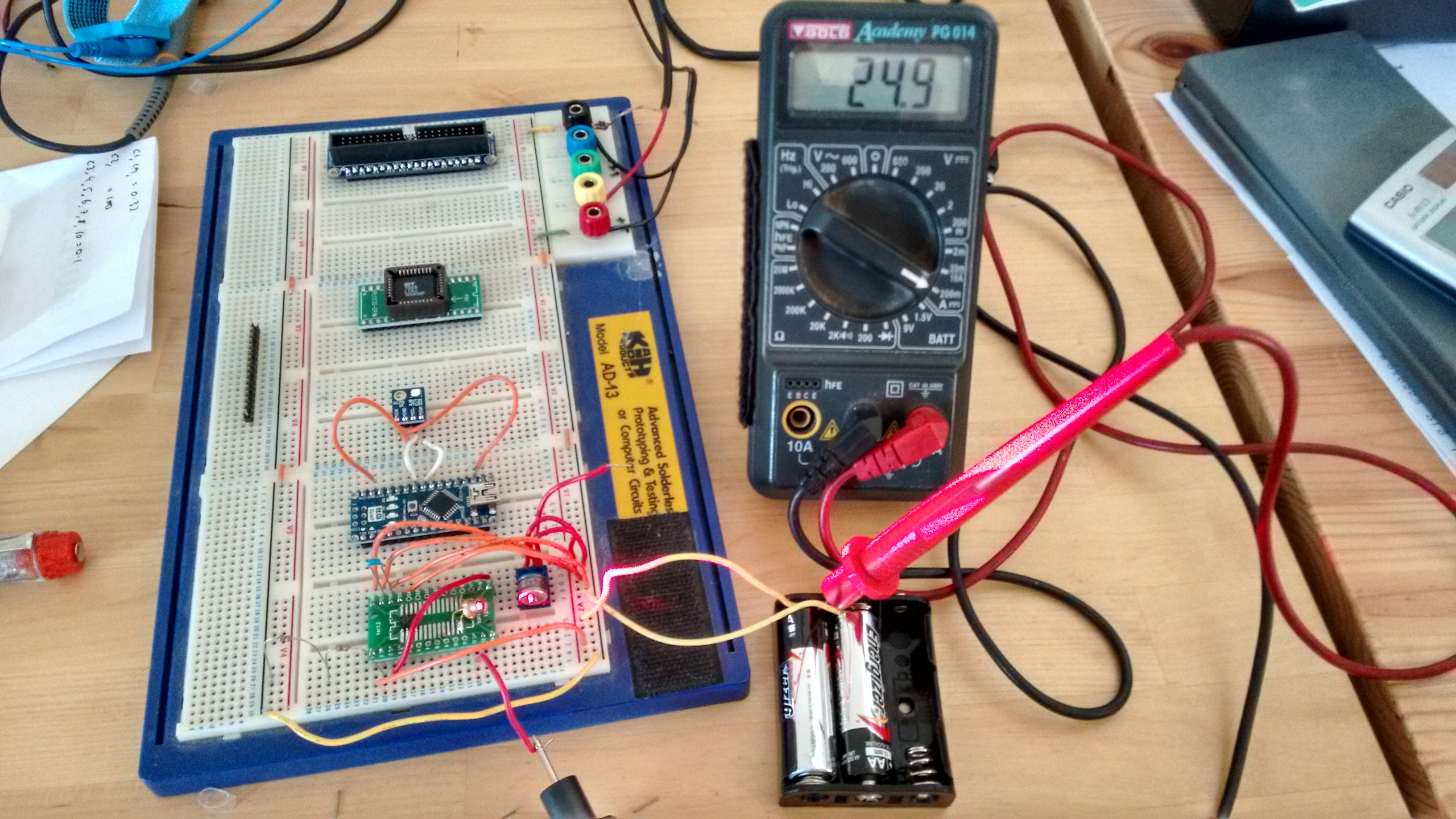
I decided to test one of the iC-HK units, to see how it behaves, connecting up to one of the small red laser diodes that will be used for the position sensing (data dump trigger) of the rotating mirror.
![]()
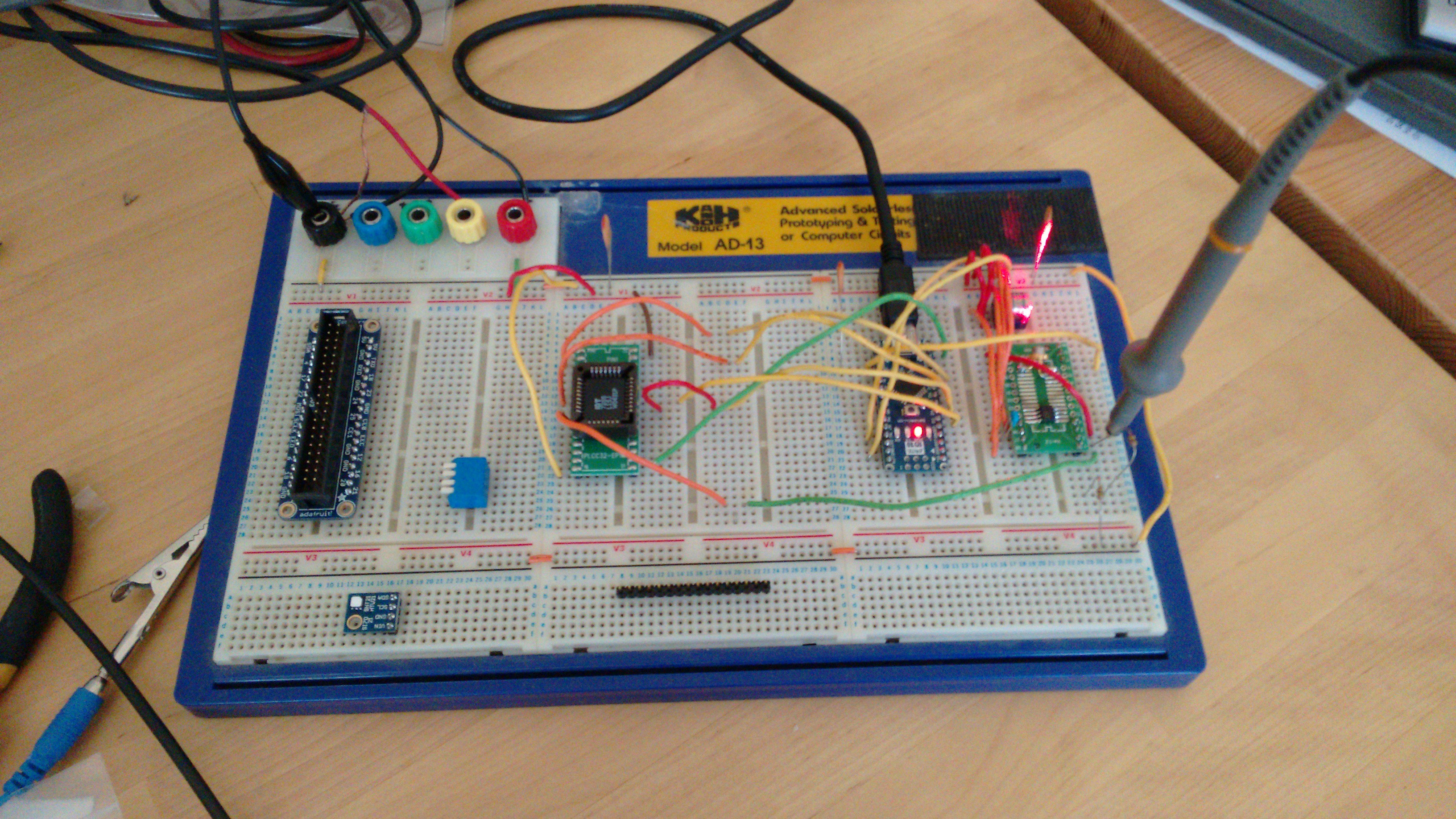
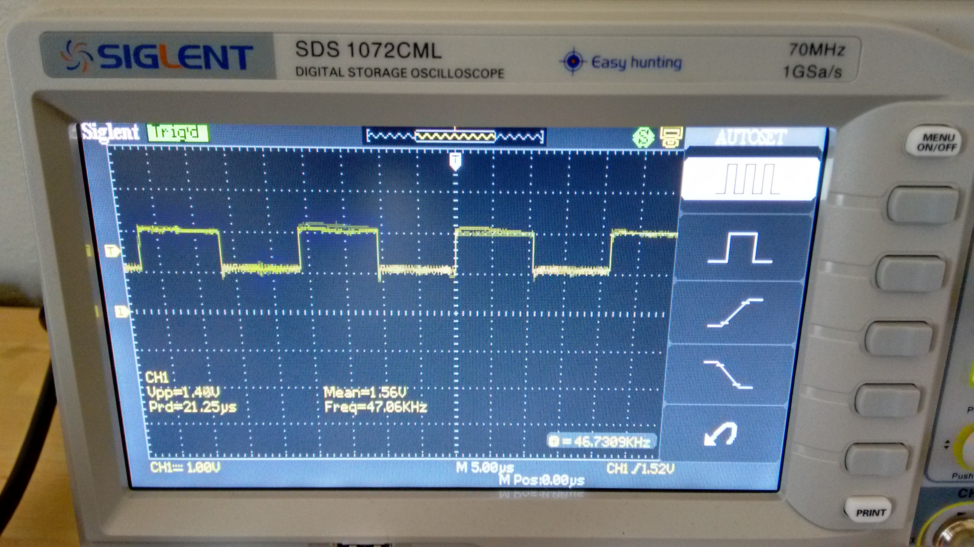
I followed this up by connecting the FIFO to the arduino and switching the laser using the data stored in the FIFO.
I need to delve into the arduino registers to get higher frequencies, but so far it is behaving as expected. The FIFO is rated for a max speed of 40MHz, the design calcs indicate a speed of 10MHz required, so I'm not expecting any issues.
![]()
![]()
-
rPi Zero break out board assembly, now running
03/19/2016 at 15:36 • 0 commentsPCBs arrived yesterday for the raspberry pi zero break out board. So after getting up to speed with a SMD practice board I've soldered up one and have enough components for a second. Quite pleased with the result for first time soldering SMD components & first time I've had a PCB made (OSH park). I made one mistake with the EasyDriver units, I did not make the outlines quite large enough so had to file off some of each adjacent board.
The Rev A2 board has been updated to it does not get missed later if more boards get made up. I need to make a 0.1" pin breakout for the flexible flat cable to allow testing on proto board. Still waiting on crimp pins to make up 0.1" connectors / leads for power etc.
![]()
Bare PCB
![]()
Populated
![]()
rPiZero & EasyDriver units fitted & running, successfully connected via SSH, still need power supply to fully test the board & stand offs to hold the rPiZero in position.
-
Micro stepper
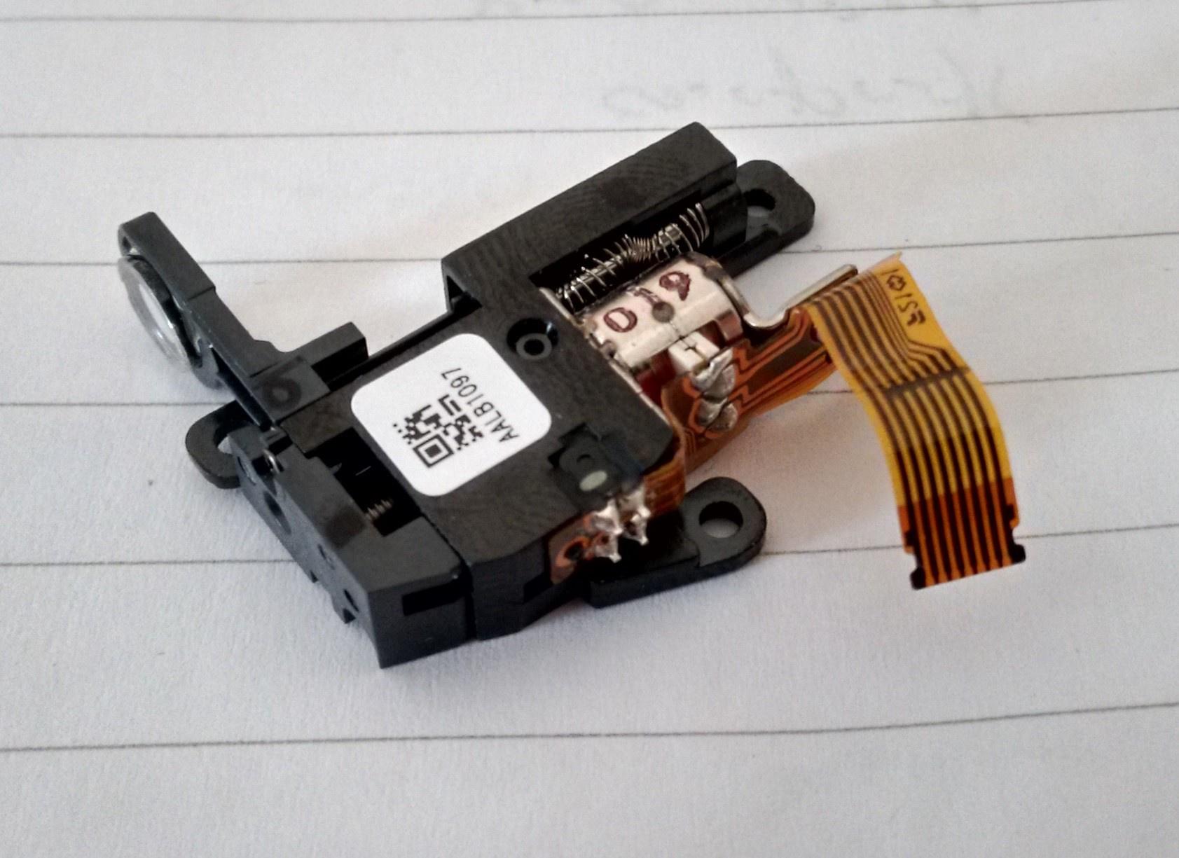
03/17/2016 at 23:24 • 0 commentsI've measured up this micro stepper powered lens unit to put in to the design model (taken from a Blu-ray drive sled). The plan is to use it to adjust the focusing lens by wire. For scale its about 30mm long, the arm has around 4mm travel.
In order to power it I identified the LB1935FA-AH bipolar driver as a suitable candidate. This requires x2 data lines to control rotation and one for power up (power saving & preventing unwanted adjustment), the IC is rated for 150mA and will cope with up to 8V max. I will probably run it at 3.3V with 5V signals. The motor coils have a resistance of 22.5 Ohms.
The unit includes an opto position sensor (left group of 4 pins) so once the number of steps is established, it can be easily zero'd.
So a total of 4 data IO lines required to run it properly.
![]()
Solidworks model - see files section (don't use without double checking)
![]()
-
Paper feed considerations
03/17/2016 at 20:46 • 0 commentsIn reviewing the paper feed methodology I've identified 3 possible options for passing the paper through the printer. I've come to the conclusion that a caddy / board based system where the paper is affixed to a board that is then passed through the printer is the most robust and lowest risk option.
Tabbed paper feeder - similar to dot matrix
Pros;- compact size
- aligned drive system
- does not rely on delicate roller system
- minimises contact with paper coating
- requires tab holes in paper
As the process requires special paper this method is not viable solution
Roller feeder - similar to traditional printer
Pros;
- compact size
Cons;
- Delicate system requiring calibration of pressure on rollers, more scope for slip errors
- requires multiple drive rollers to minimise pressure required, high complexity
- roller contact with paper, may cause problems with coating chemistry
A high risk options that can be foreseen to cause many headaches in its setup, and may prove unusable.
Board/Caddy feeder - similar to CD printer
Pros;
- can be arranged so that drive system does not need to contact paper
- lower complexity
- more robust system possible with higher roller loads to drive board
- paper can be taped down to ensure flatness
Cons;
- double space required as the board will be at each end of the printer at some point
Selected option, more space required, but most robust and practicable option at this stage.
Direct UV Printer for Alternative Photography
Design of a UV printer for making exposures of Alternative Photography prints, direct from a digital image

 Upper head board has the I/O headers for TEC, trigger laser, mirror motor controls and variable frequency generator for the FIFO readout clock. This last is to ensure a hardware based readout system for the FIFO to ensure that laser strip aligns (within 1 clock wavelength) with the adjacent one.