David Brown
-
Long exposure chemistry check
03/14/2016 at 03:14 • 0 commentsFor a maximum assumed print size of 400mm x 500mm my current design calculations put the print time at 2.25 hours, this is a reasonable amount of time where the unexposed coating/emulsion will be waiting for exposure and the exposed emulsion will be waiting for processing.
So I've run a test, from a strip of paper coated with the emulsion I cut 10 strips (after drying) and over a period of 2.5 hours I exposed a strip every 15min. With a control strip that was left unexposed over the full duration. This gives a realistic test of the printing process where the exposed emulsion is waiting for up to 2.5 hours before processing.
The results show that over the time period in question (for temperature 24'C, and humidity ~60-80%) there is negligible variation in result. I ran the test in parallel with New Cyanotype test strips which performed similarly. It should be noted that Cyanotype requires double the exposure time to Kallitype, but is a print out method, so I don't expect any issues due to dark reactions. Which was my main concern with the Kallitype chemistry.
Palladium toned Kallitype test strips
![]()
Exposure time was 1:30s on my UV LED light box (395nm), paper was Arches Platine
-
2A Stepper Driver
03/12/2016 at 02:35 • 0 commentsBy using the EasyDriver units to generate the bi-polar stepper motor signals larger motors up to 2A per phase can be using a L298N driver or multiples for larger currents.
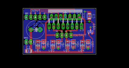
Below is a simple compact board as a solution I've come up with to allow me to use the 1.5A stepper motors in this project. The circuit is based on the example provided in the datasheet but using SMT components to minimise the overall size. This takes the common 24v supply that will power the whole system.
![]()
![]()
-
Alternative Photography Chemistry
03/12/2016 at 00:35 • 0 commentsThere is quite a lot of information available on the web regarding the chemistry of the Kallitype and Cyanotype processes. At their core they rely on the photo-sensitivity of Iron (III) complex, either iron (III) oxalate hexahydrate or ammonium iron (III) oxalate.
This chemistry is orders of magnitude less sensitive than the common silver black and white photography chemistry that requires a dark room. Iron methods simply need to mitigate the UV, a closed blind with daylight or a medium tungsten bulb illumination suffice.
The exposure duration is calculated using the quantum yield of the iron (III) complex, this being the number of interacted molecules per photon of light. And the various absorption process, known as the molar attenuation coefficient. For Kallitype this is for the ammonium iron (III) oxalate, for Cyanotype it is the ferricyanide product, which produces a masking effect that effectively doubles the exposure time compared to Kallitype process.
The iron process is most sensitive to wavelengths of roughly 300nm, unfortunately laser diodes of reasonable power are not available at prices that feasible for this project. The most powerful reasonable laser diodes generally available are 405nm wavelength bluray diodes. These are available up to 900mW, which in this instance i'm looking at running at 450mW with TEC peltier unit to control the temperature. From my calculations at this power and wavelength using approximate standard coating concentrations the exposure time for Kallitype is ~2.6uS.
Calculations are in the exposure calc pdf, currently at rev.A2 If anyone spots any holes let me know. The numbers are the right order of magnitude, based on my current exposure methods and the units work out correctly.
I'd like to thank Mike Ware for providing advice on the calculation methodology for exposure duration.
-
RPi Zero breakout board
03/12/2016 at 00:03 • 0 commentsThe printers brain will be a Raspberry Pi Zero computer, with a servant Arduino in the printer head itself to provide flexible monitoring and control functions on the fly. Initial calibration and static settings will be set at system startup (using MCP23017 s to set DACs, frequency generator, etc.) so wont require resources during the printing process.
This update is for the breakout board to allow the Raspberry Pi Zero to;
- Utilise 5V logic (using x3 ̶T̶X̶B̶0̶1̶0̶8̶ ICs) - NOW USING TXS0108
- Bring the USB out to a sturdier USB-B female socket
- Integrate x2 EasyDriver stepper boards, with selectable 5V / 24V feed to allow use with L298N driver for larger current motors.
- Provide a ribbon cable connection for x15 logic lines and power (24v required for the polygon mirror motor) to the printer head
The following Eagle CAD layout of the breakout board, shows the rPiZero and EasyDriver units with the x3 voltage level converters.
![]()
3D CAD model to check assembly below. POGO pins used to connect out the USB from the test pads on the underside of the rPiZero. nylon stand-offs will be used to secure the boards.
![]()
Direct UV Printer for Alternative Photography
Design of a UV printer for making exposures of Alternative Photography prints, direct from a digital image