-
1Step 1
Cut the fan hub out of the frame, then cut off the blades. PRO TIP: use some hot glue as a strain relief on the wires.They tend to break off easily with all the handling. Holding the motor against a bench belt sander and rotating it is a good way of removing the leftover bits of blade.
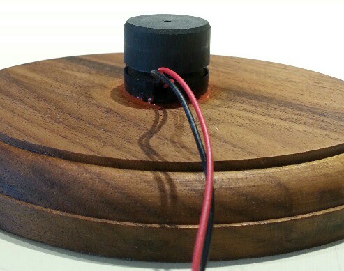
Below is the fan motor cut down and mounted. I used silicone caulk to glue it to a base I had kicking around.
![]()
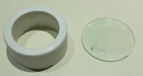
Below are the coil mountings. The disc is cut from a CD and is the same diameter as the coil. The aluminum layer must be removed - put some tape on it and pull and it should come off. The hole is drilled for the inside wire of the coil.
The ring is a cut-down 1" PVC pipe cap. I used a metal lathe, but if you don't have one a bench belt sander can be used to shape it. The hole can be drilled to approximate size, then a 1" drum sander in a drill press can finish it off. The hole should be the same diameter as the inside of the coil. The ring height should be adjusted to position the lower coil 1 mm from the upper coil. Note the slots cut in it for the coil and fan wires.
![]()
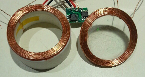
Here's the coils mounted. Silicone caulk was used after the Kapton tape was removed from the coils.
![]()
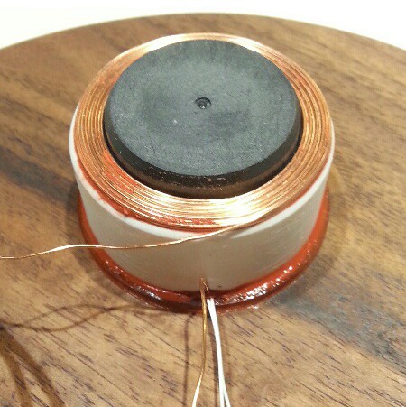
Here's the lower coil mounting glued to the base with silicone caulk. The white wires are for the fan motor: the originals broke off. NOT SHOWN: I shimmed the mounting temporarily with a strip of cardboard between the coil and the fan hub to keep everything centered while the caulk was curing.
![]()
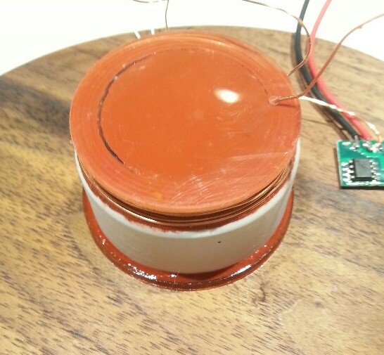
I then glued the upper coil on the fan hub with silicone caulk.
![]()
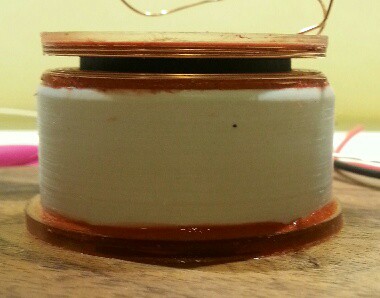
Here you can see the coil spacing. If I did it again I'd make it about half this thickness.
![]()
-
2Step 2
ZERO MOUNTING
NOTE: the following instructions are speculative. I haven't actually got a Zero yet to test them. I can see it in my head though.
The power supply board is attached to the SD card socket with double sided foam tape. It's wired to the 5V and ground pins near it.
4-40 standoffs are installed on the two holes by the SD card socket, one standoff on top and one standoff below for each of the two holes. The lower two standoffs are covered with heat shrink tubing.
The LEDs are soldered to the circuit board following the markings. Resistors are soldered to the Zero then bent over and inserted into the LED board. Align the board so it's touching the corner of the Zero and is facing out from center then solder the resistor leads.
The zero mounts on the disk with double sided foam tape. The heat shrink covered standoffs should touch the side of the coil.
...mount IR sensor
...wire base
BALANCING
Add nuts to the spacers to balance. More instructions soon...
Discussions
Become a Hackaday.io Member
Create an account to leave a comment. Already have an account? Log In.