Alexandre LE GALL
-
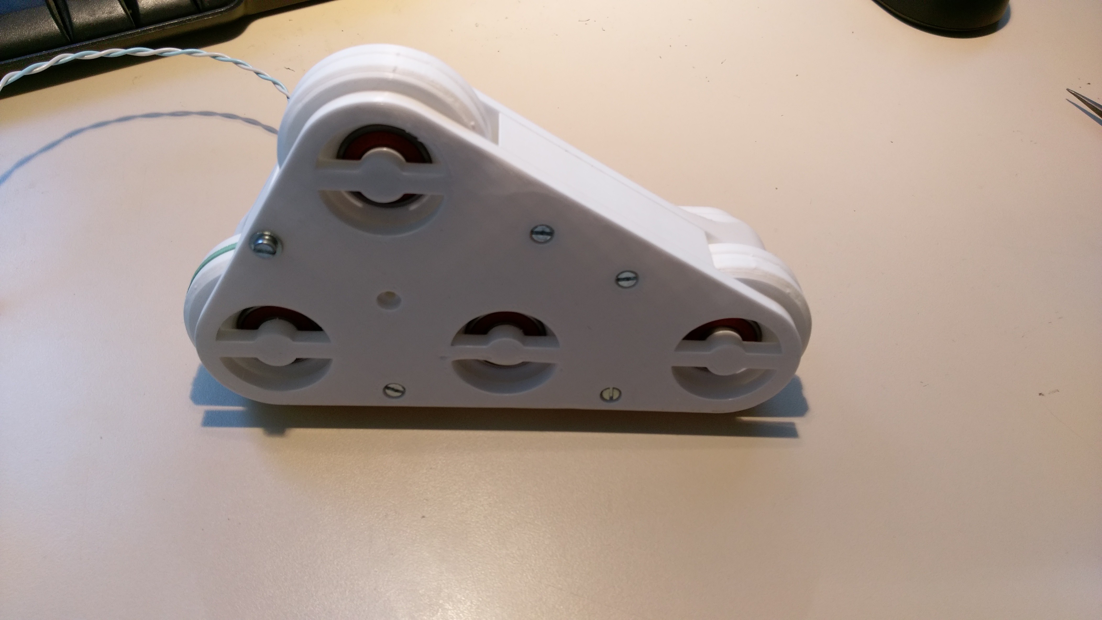
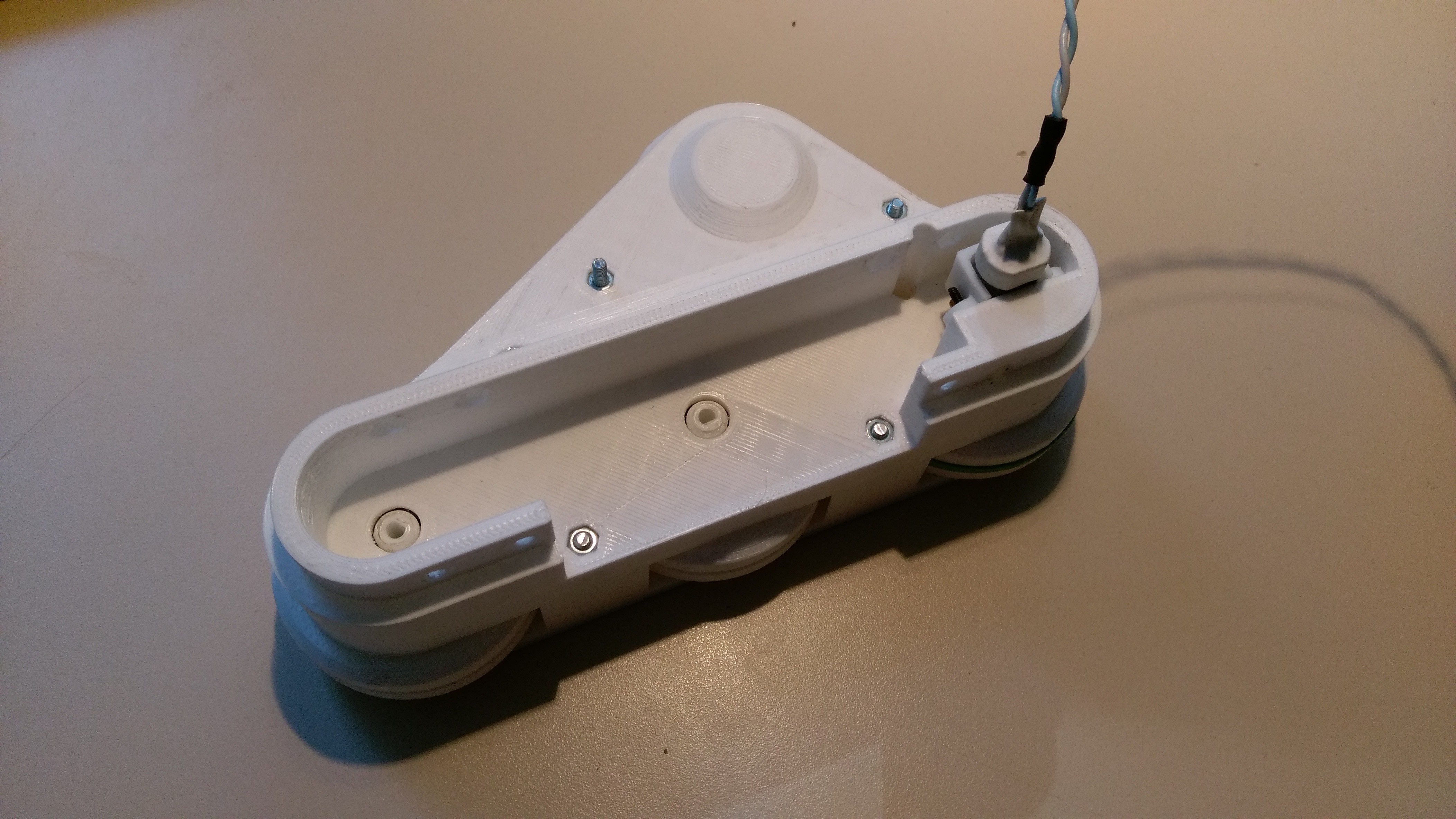
3D CAD in progress.
07/12/2018 at 10:55 • 0 commentsI am currently doing the 3D CAD of the robot body.
For the moment, the robot has no caterpillars. I prefer to stay simple and use wheels for the first prototype.
Here is the right part :
![]()
![]()
I need to make some adjustments before printing the left part.I still have to do the central part (on which will come the electronics and the potato).
In the following days, I will try to update my github repository and add details to this project page.
-
It's (almost) working !
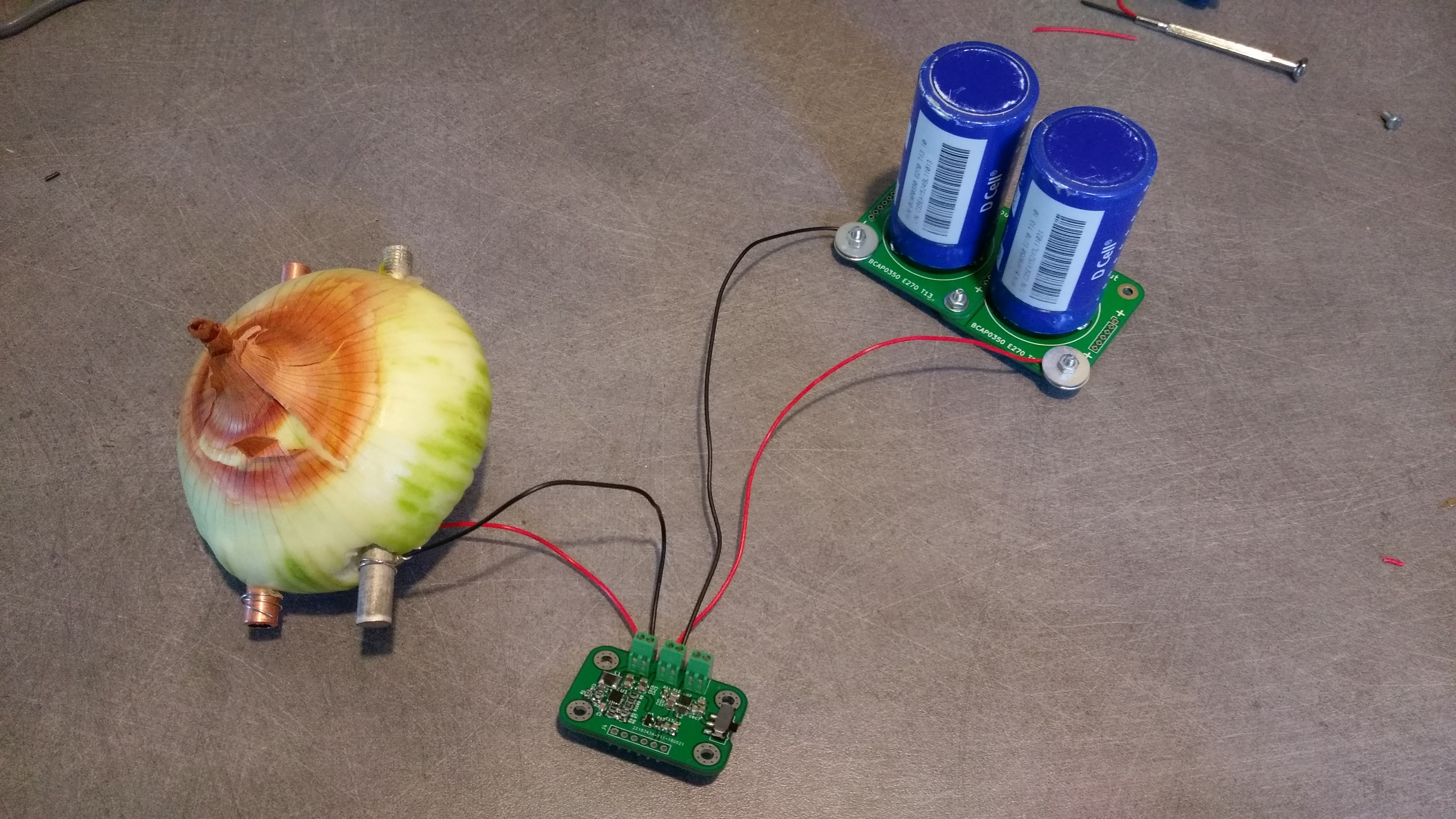
07/10/2018 at 21:06 • 0 commentsI didn't have potatoes at home, so let's build an Onion Robot for now !
![]()
The two supercapacitor are slowly charging (i didn't measure the current/voltage/energy but it's charging) and the undervoltage, overvoltage, good battery indicator work well but the 3V3 regulator can only power very small load when it's connected to the BQ25504.if i want power bigger load (the i2c motor driver for example), i have to connect the regulator input directly to the supercapacitors
I think the problem of power limitation comes from my layout. I will try to modify the board with tiny wires and fine soldering skill, until i make a version 2 of this board.
The i2c motor driver works perfectly well (μController, H-Bridges, and quad comparator).
I am currently working on the body of the robot (it will be printed in 3D). I hope to post some photos or pictures soon.
-
Soldering done !
07/05/2018 at 18:45 • 0 comments![]()
I just finished soldering the boards.
I made some mistakes but it was easily repaired.
I have not yet test everything, but the buck boost converter (energy harvesting module) and the quad comparator (motor driver module) is working properly.
Tomorrow, I will try to flash the microcontroller, and test the the H-Bridge ICs...
-
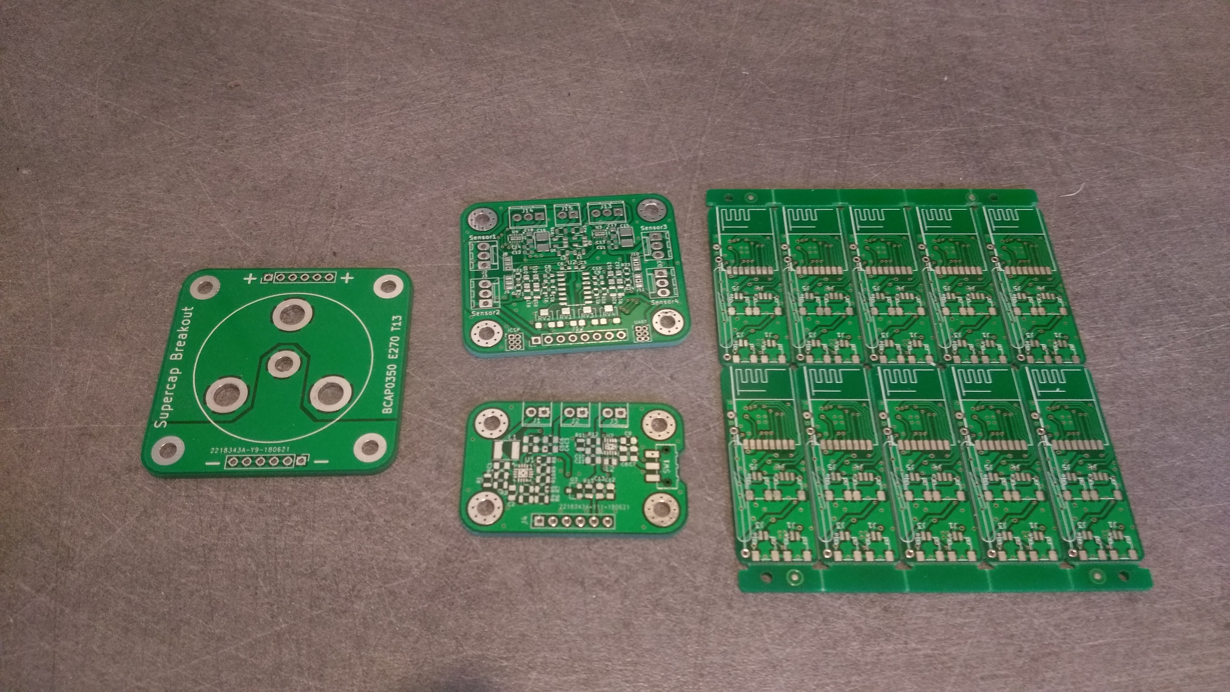
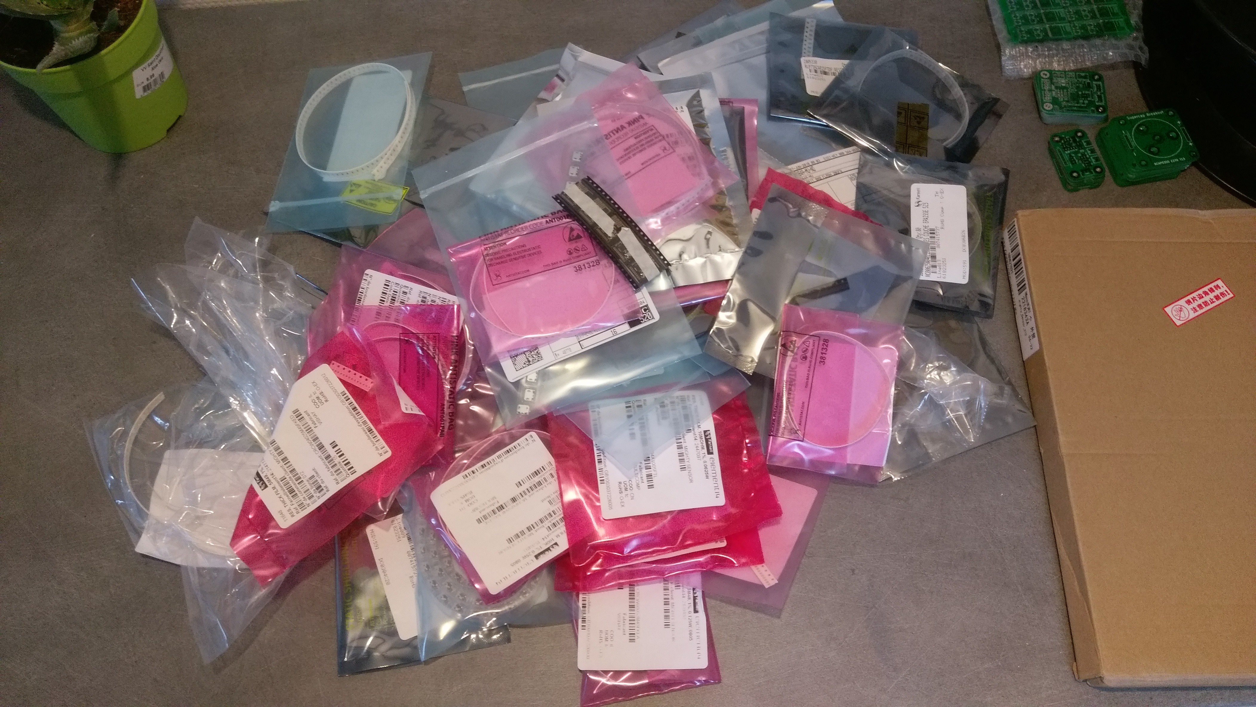
PCB and components finally here !!!
07/01/2018 at 19:56 • 0 comments![]()
![]()
-
Problem with the gerber files ??
06/07/2018 at 08:35 • 0 commentsI wanted to send PCB in production, but i have a problem with the gerber files of the harvesting module : The online gerber viewer (from JLCPCB) does not want it.
There is no problem with the other two modules, and i use the same export parameters.
I tried to export with another computer (and a different OS), but the problem persists.
I also tried to upload the files to another PCB manufacturer (EuroCircuit: we use this manufacturer at my job, but it's a lot more expensive than the Chinese manufacturer), and it works this time...
I don't understand where the problem come from...
I have to look at this more closely (waiting for the results of the robotic contest).
-
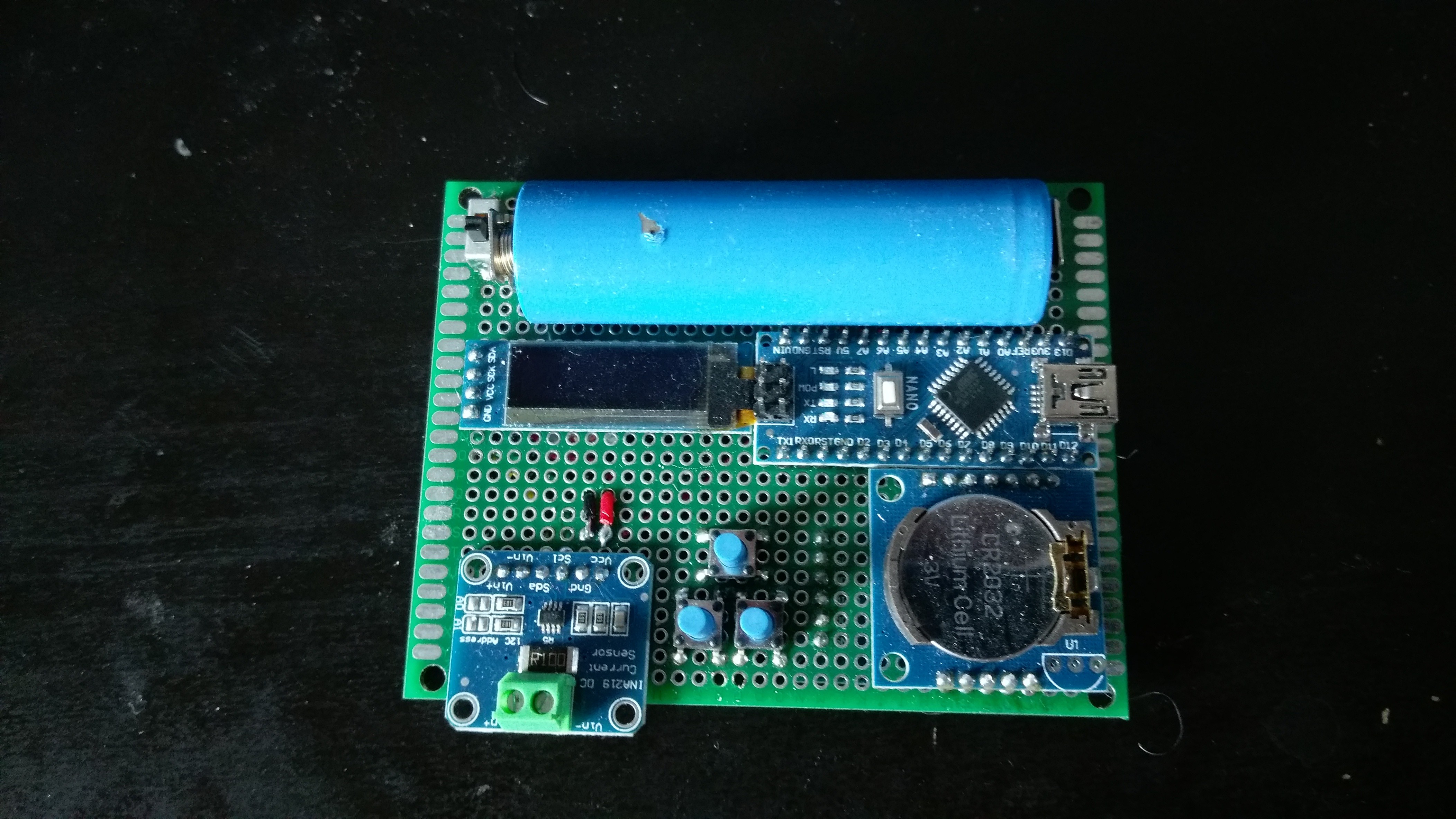
Arduino Energy Logger
06/04/2018 at 14:02 • 0 comments![]()
I'm currently building an Arduino Energy logger.
It's made with what i have on hand :- Arduino Nano
- INA219 Current Sensor (actually with an 0,1 Ohm resistor, i need to change that if i whant mesaure micro or nano ampere)
- RTC module
- SD card breakout (bottom side)
- 128x32 Oled Display
- 18650 Lipo battery + lipo charger module + 5V boost converter
It will be useful for measering power and energy that i can harvest from a potato...
-
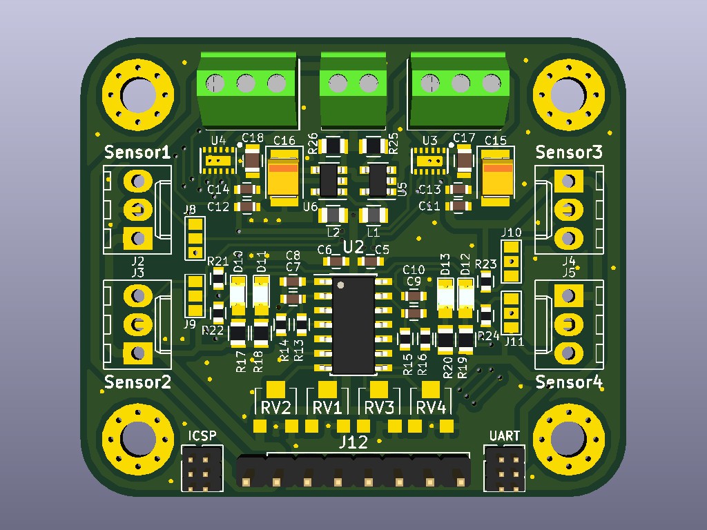
Motor Driver Board
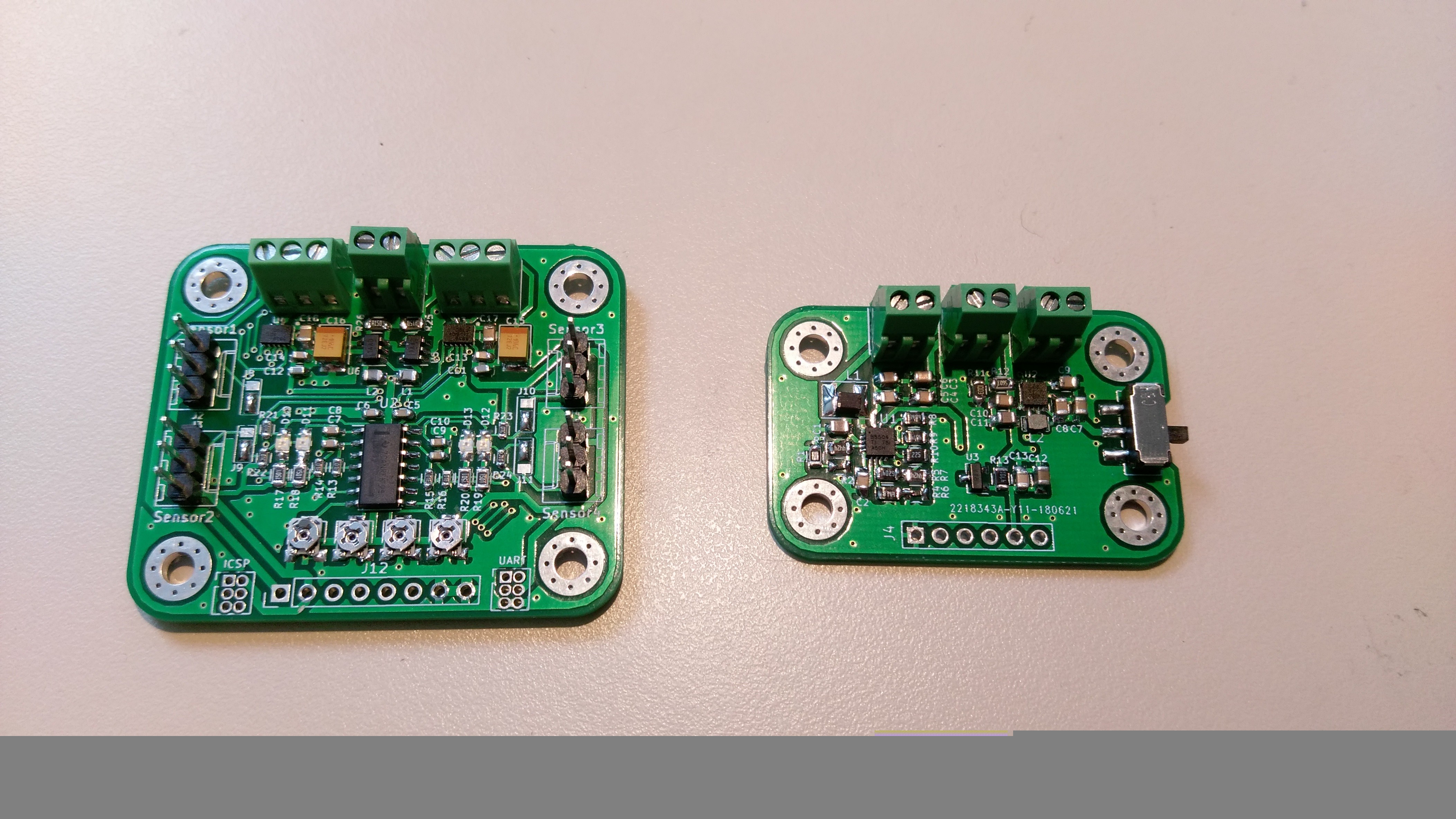
06/04/2018 at 13:59 • 0 commentsI'm just finished the I2C motor driver board.
There is :
- 2x DRV8839 dual half-bridge driver (it can drive 2 motor in both direction, or 4 in single direction)
- 2x INA180 Current Sensor (1 for each driver)
- 4 sensor input (analog, or digital with a LM339 Quad comparator)
- Atmega168 or 328P (for I2C interface, Speed Control and monitoring)
It's perfboard/breadboard compatible (except for ICSP and UART programming connector).
![]()
![]()
-
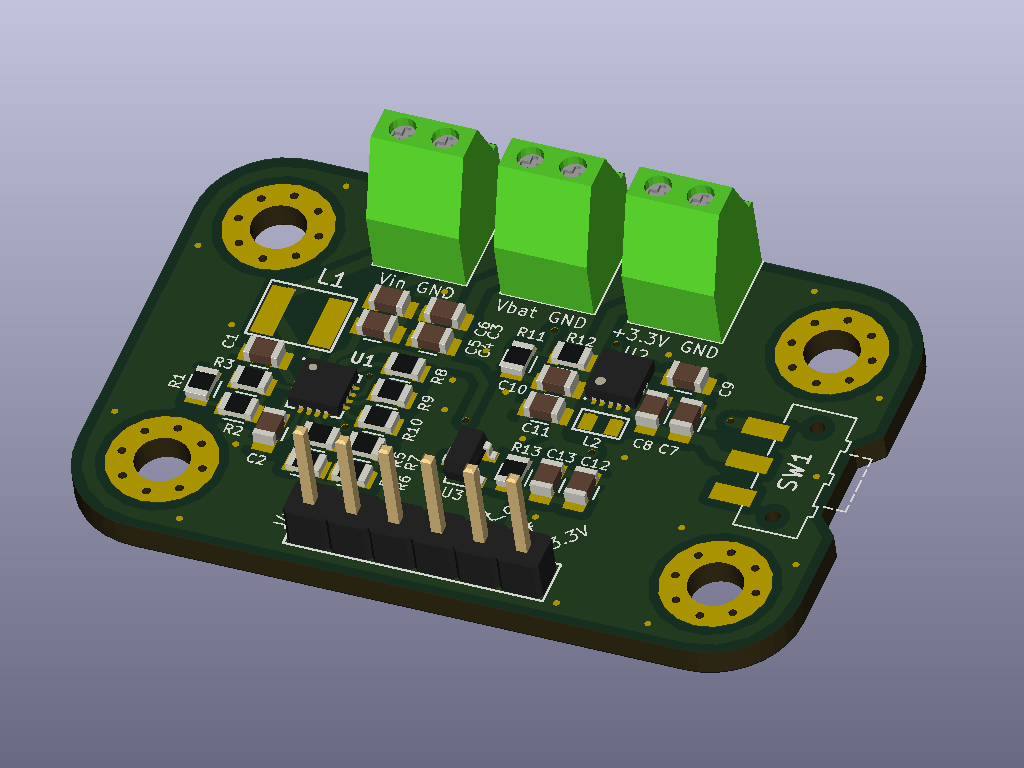
Energy Harvesting Module
04/20/2018 at 21:03 • 0 commentsHere is a 3D model (kicad 3D view) of the Energy harvesting module.
It is based on a BQ25504 Energy Harvester (with MPPT and Battery management), pair with TPS63030 Buck/Boost Converter. It's perfboard/breadboard compatible.
There is also a 1V precision voltage reference.
You can adjust the parameters (Under & Over voltage protection, Output voltage...) by changing the value of some resistors.
![]()
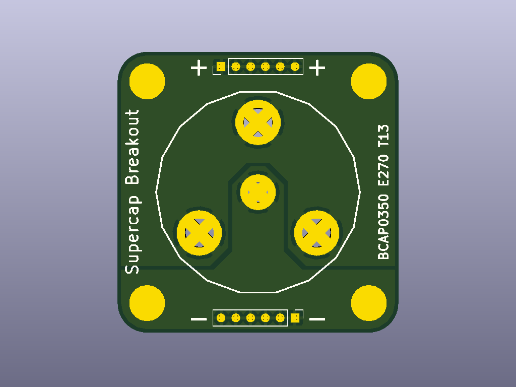
I also made a breakout board for BCAP0350 E270 T13 Supercap (350F, 2,7V).
It's also perfboard/breadboard compatible, but you can use M3 Mounting Hole as terminals if you want (for high current).![]()
There will be more details (explanation and schematic) on the main project page.
I still have to do the other modules (I2C motor driver, sensors...) before I can order PCBs and components (and wait for my salary).
I also have to open a GitHub repository to share files and documentation, but I have never used it ... -
Somes calculations = autonomy of +60 minutes
03/27/2018 at 11:09 • 0 commentsI juste made some simples calcultation to find out if it's possible to power the robot with potatoes energy.
The energy is harvested from a single potato in two super capacitor (2.7V / 350F).
If i place the two capacitor in series, it gives me a single capacitor of 5.4V / 175F.
The energy inside capacitor is :
I don't want overcharge it, so i will charge at maximum 5V :
To extract maximum energy from capacitor, i need a boost converter. Because of the energy harvesting IC, i can't discharge over 2.2V :
I can store and use 2187.5 - 423.5 = 1764 J (0.49 Wh)
At 3.3V, my two motors use each 25mA (light load). (3.3V * 25mA = 82.5 mW)
The electronics (µC, sensors... ) sould use maximum 50mA. (3.3V * 50mA = 165mW)
In total, i need 0.33W. (2 * 82.5mW + 165mW = 330mW)
With 75% efficency boost converter, i should use 0.44W of power from the capacitor.
With a consumption of 0.44W and a capacity of 0.49 Wh, i can power the robot for 1.11 hours (66 minutes, 49 seconds)
If i want know how long i can charge my capacitor with potatoes, i have to measure how much power i can exctract from it...
Edit after some datasheets reading and power consumption measurement of my new tiny motor...
Modular Potato Powered Robot
Powering LEDs or clocks with potatoes is too simple for you ? Let's build a modular robot powered by a single potato !