Norbert Heinz
-
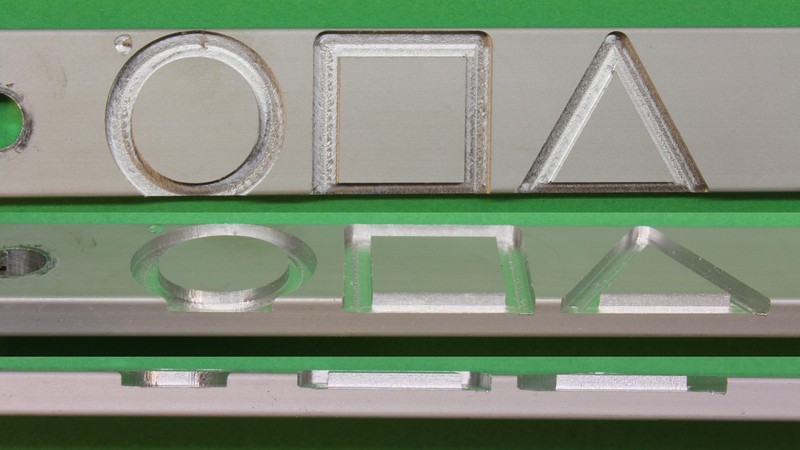
CNC v3.2 is in fact a tool, not a toy!
10/16/2016 at 07:56 • 0 commentsSomeone on YouTube stated that machines like that would bend like bamboo under load (in a politely way, it's obviously somebody that knows about the "qualities" of cheap machines). My CNC v3.2 is a solid build with a weight of more than 60kg. To demonstrate the capabilities of the prototype I have carved another test piece of aluminium at the end of my video about the mechanics (starting at 9:37):
The result looks promising:
![]()
Have a look at the full resolution image.
To get that result I have used a 3.2mm router bit and added a continuous flow of water. The circle goes from the router to the bowl underneath the router table into a bucket under my workbench, from there into a watering can, manually into a reservoir on top of the machine and finally back to the router. The pump I had in stock for many years was obviously broken...
Something that bends in fact like bamboo is the cheap router motor with it's plastics housing. which results in deviations that are visible in the test piece at the starting / end points. Have a close look at the bottom left of the square and the triangle and at the top centre of the circle. Nonetheless the straight edges of the square and the triangle are great (considering the low tech configuration currently in use). The dimensions of the shapes hit those of the template with an error of less than 0.1 mm.
More citizen science must follow to express the quality of this machine in numbers. It's the only way to find the weak points and so to improve the design.
-
The 2016HackadayPrize comes to an end, soon.
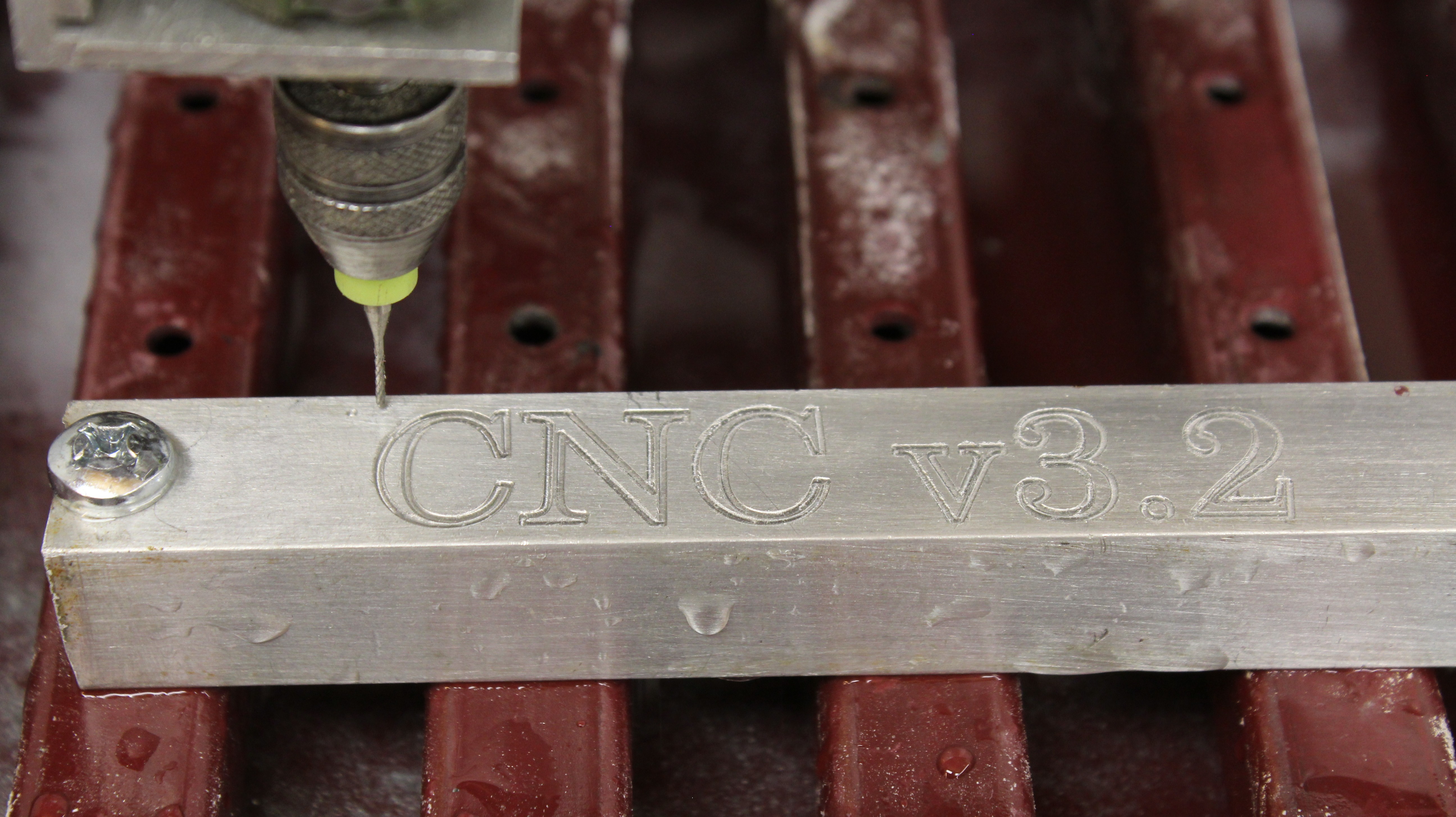
10/11/2016 at 17:22 • 0 comments...which doesn't mean that this project comes to an end, too. I have created a promotion video for the final judging:
The major improvement since the first test run is the adjustable table with a bowl underneath that enables to create a circular flow of coolant in the near future. I have engraved another piece of aluminium using more water to remove the chipping, giving a smoother result. A pump and a skirt around the router will be installed soon, to make it even better. Have a look at the full resolution picture:
![]()
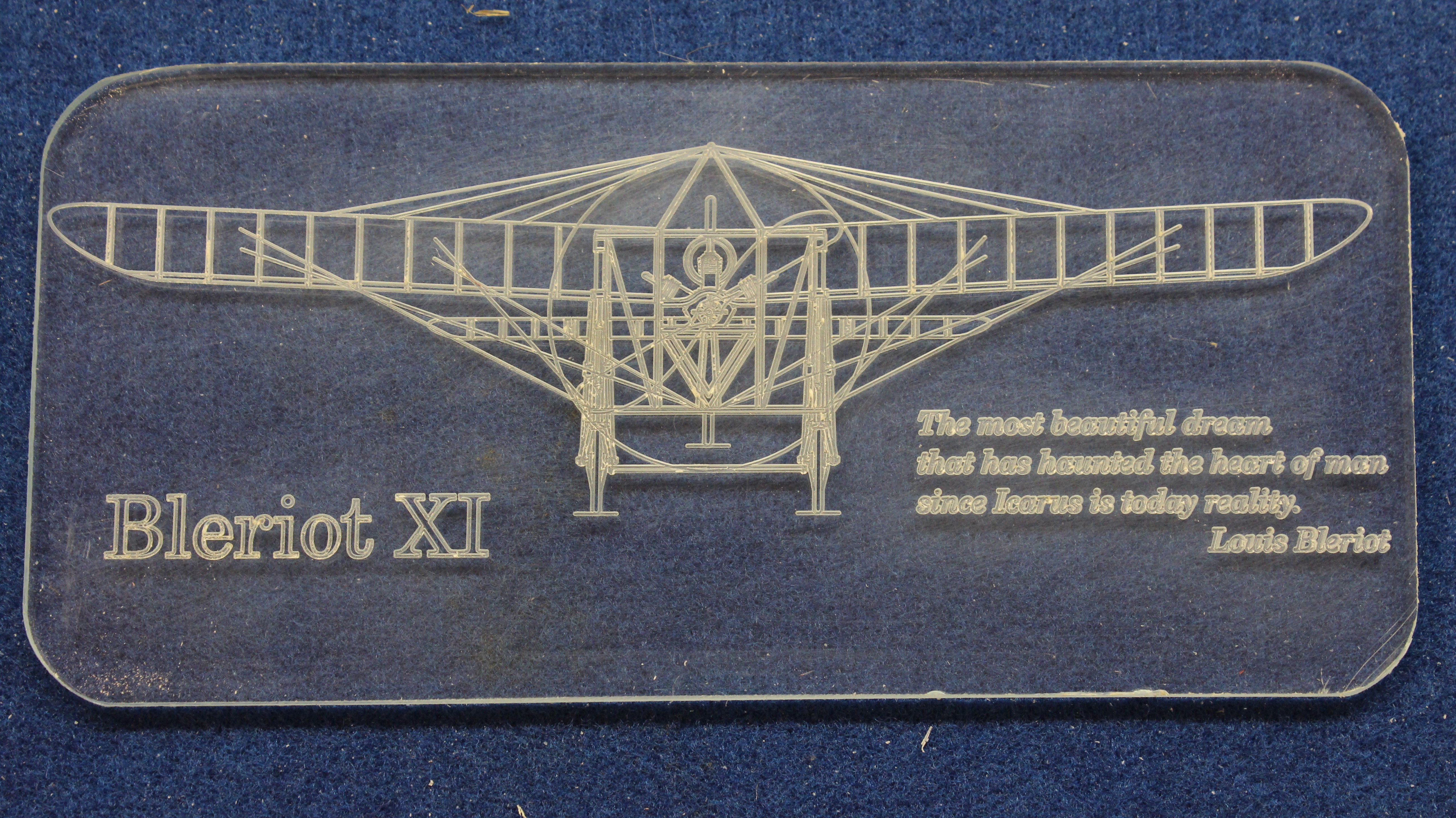
I have also engraved and cut a piece of acrylic plastic. The machine is still very slow since I did not make any changes to the motors or the quick and dirty software. The characters have a height of only 3mm and the text is clearly readable, isn't it?
![]()
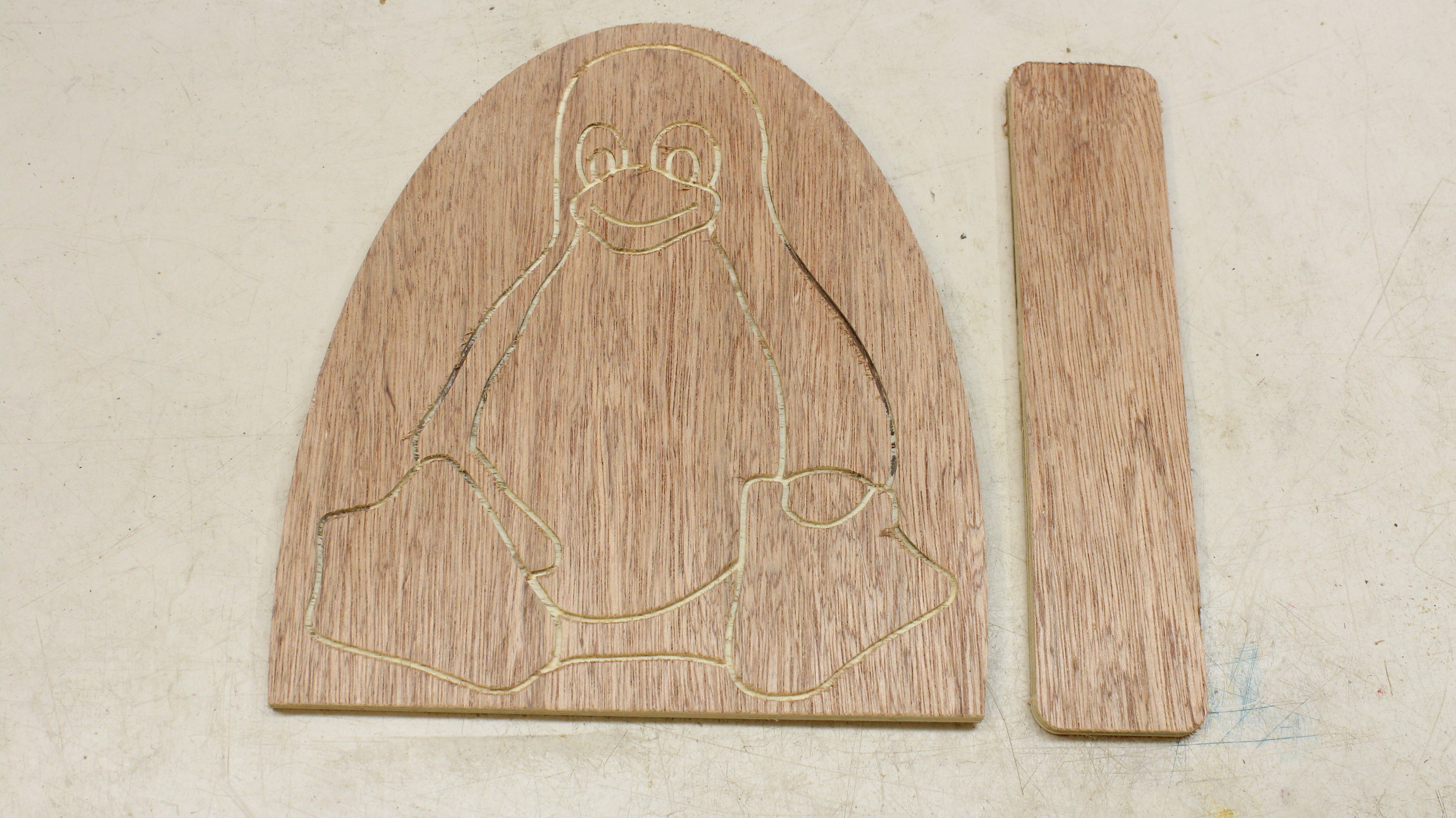
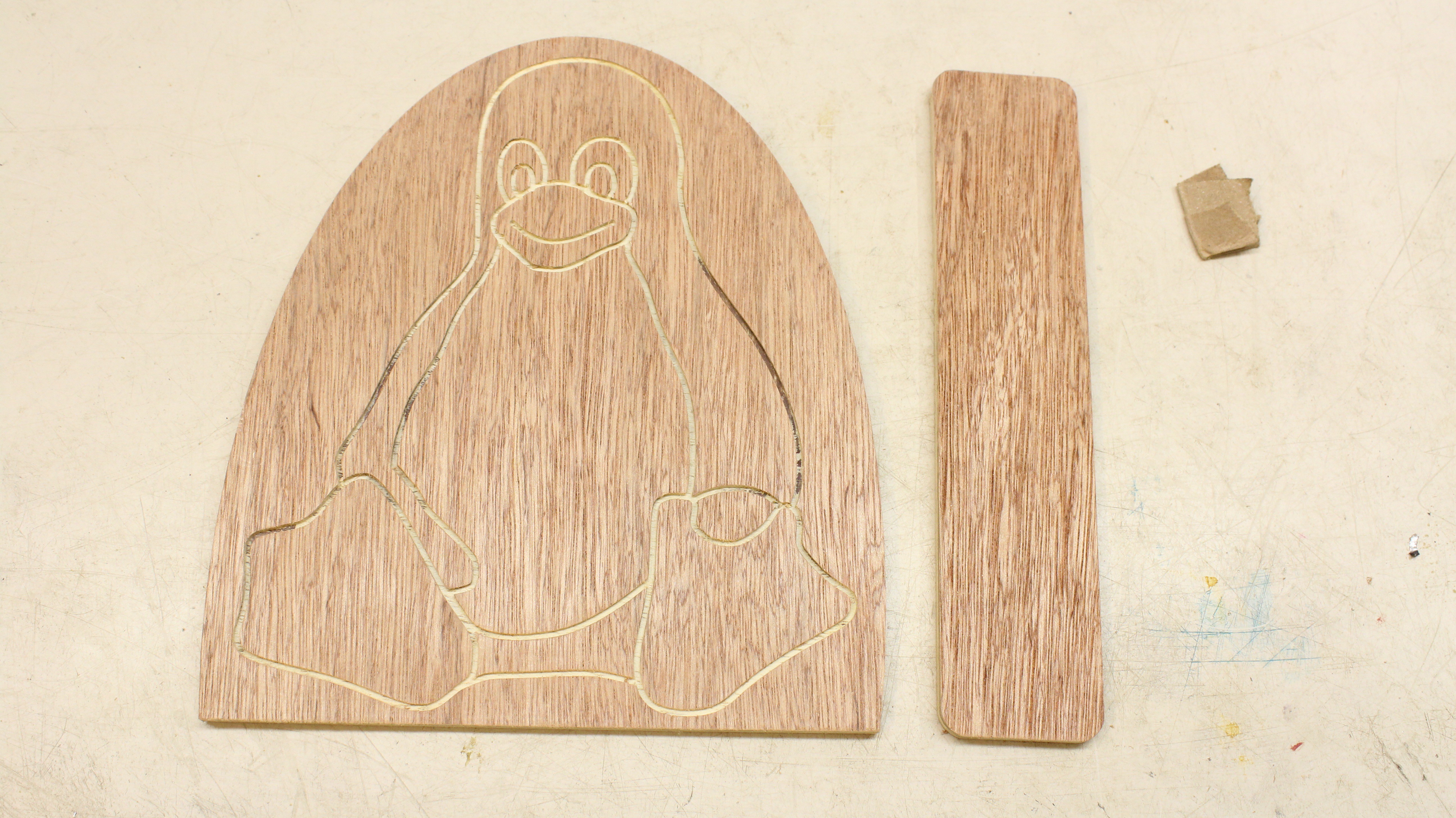
Processing plywood also works fine. I will have to play around with different router bits to get less rough edges. There are bits with a counterclockwise cutting spiral resulting in smoother edges on top, so that the engraved penguin will look better:
![]()
After sanding the edges it looks great:
![]()
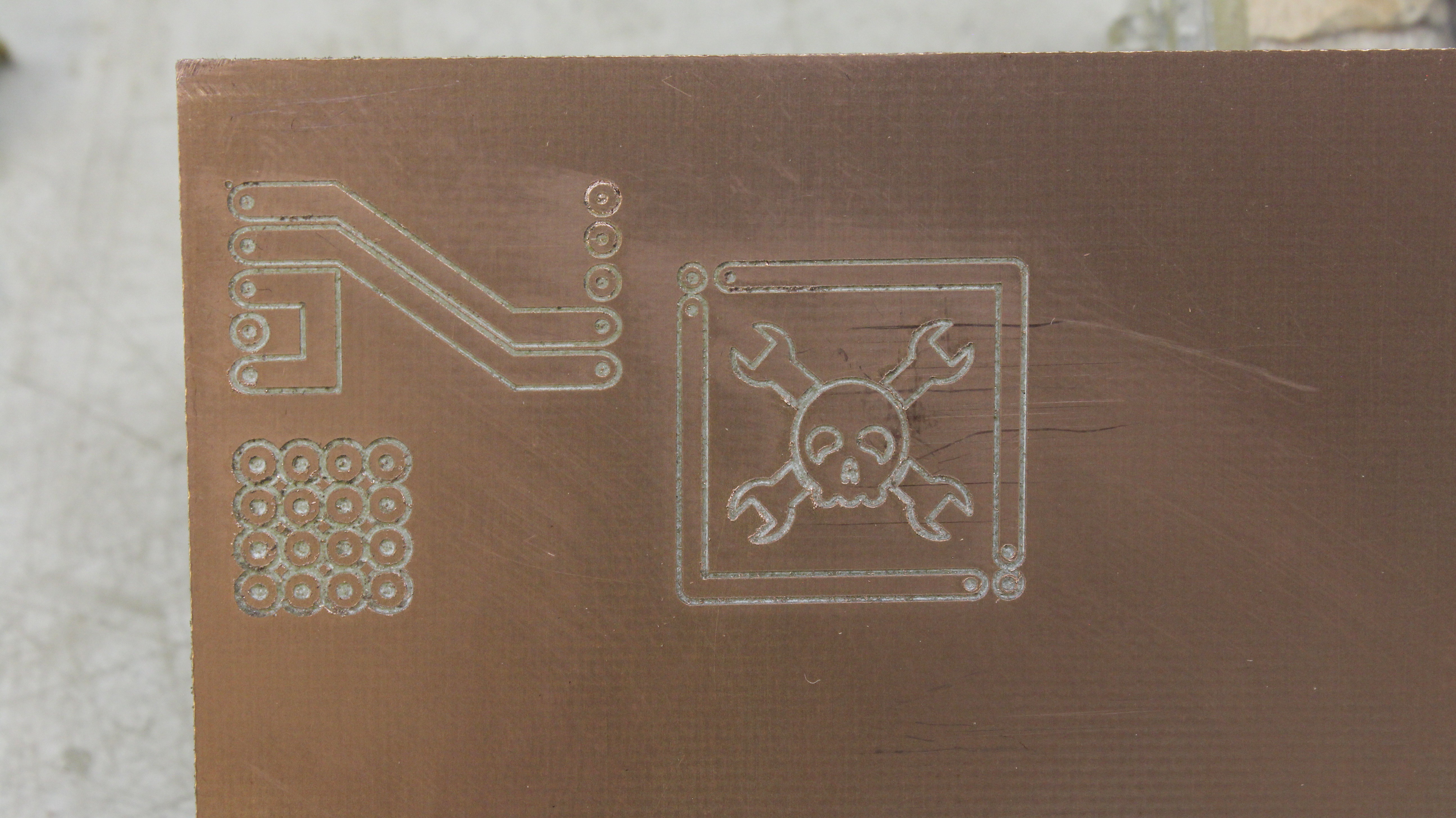
Engraving a copper plated board is better now, but still not perfect. The sheet bends and vibrates on the table. I will add a special mount for making circuit boards. The software still allows to process only *.svg files, thus in principle this is no circuit layout. Once again the 16 dots on the bottom left are arranged on a 2.5mm grid as used in prototyping boards. Trying different V bits is also on my list of things to do. The aluminium tube connected to a vacuum cleaner removes the chipping which results in smoother edges:
![]()
-
My assistant lives!
10/03/2016 at 13:52 • 0 commentsIt took me a last night shift to finally bring my CNC v3.2 to live. It's the low cost confguration using the optical sensors and DC motors from the old printers I scraped for a couple of previous projects. Once more there is:
Creating a simple to build machine is no simple task! The test run I started yesterday evening was a failure. The X axis lost steps, which should be impossible in a closed loop system. I changed the optical sensors, the H bridge motor drivers, the motors - nothing! Finally I found that the cheap 4 conductor cable used for the sensors (non shielded) caused the trouble. When removing it from the nearby motor cables it finally worked late this night...
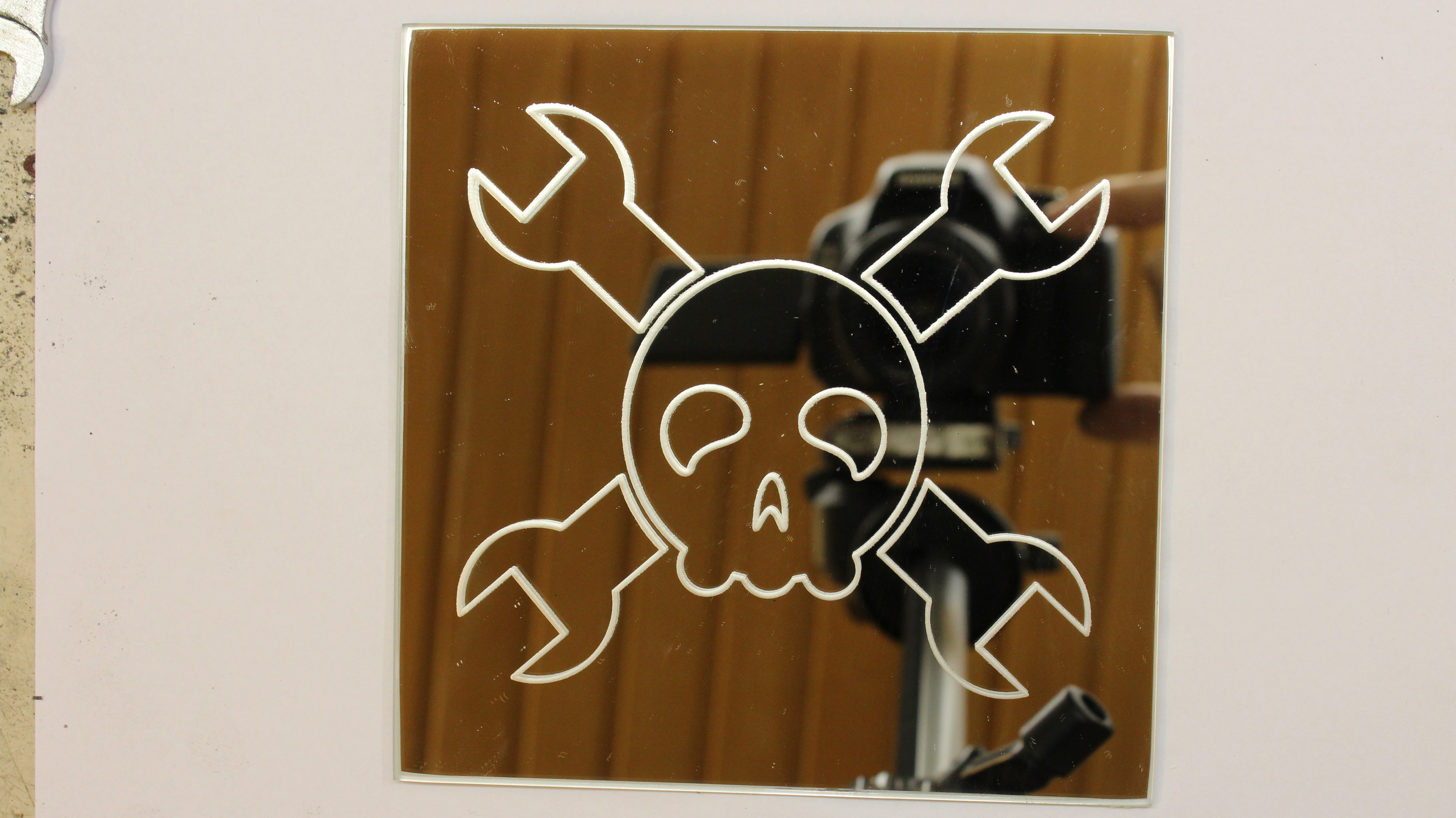
I have created a short video demonstrating engraving glass, milling copper plated board and finally milling solid aluminium (a small piece I found in my workshop):
The results in pictures:
1.) Engraving glass works fine. The endpoints of the paths hit their starting points.
![]()
2.) Milling a PCB. My prototype software can't process gerber files, thus I used the Hackaday logo with a special border. The left graphic is 20x20mm with 1mm border, the right graphic is scaled to 40x40mm. The dots simulate a 2.5mm solder points grid as used on prototyping boards. The bed wasn't levelled, the board not flat on ground, the router motor and V bits were cheap, nonetheless the rings are at least okay (not perfect). Milling PCBs requires a better preparation, thus future results will become better.
![]()
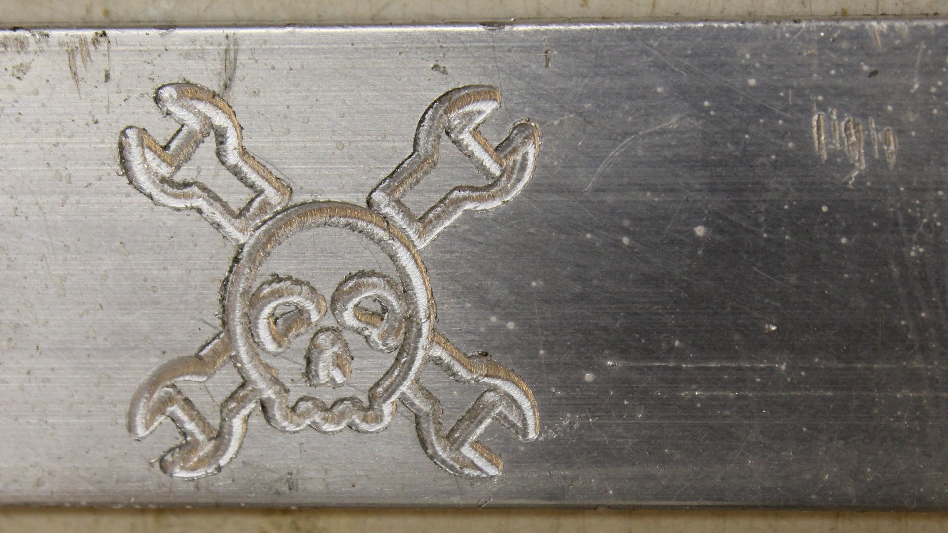
3.) Milling aluminium. Working with a just very roughly adjusted machine, wrong software parameters and a cheap low power router motor cost me a router bit. The logo is 15x15mm, cut with a 1mm router bit.
![]()
-
A big thank you for another paycheck from Supply Frame Inc. !
09/20/2016 at 19:38 • 0 commentsMy CNC made it to the Automation finalists of this years HackadayPrize:
http://hackaday.com/2016/08/29/hackaday-prize-20-projects-that-are-the-height-of-automation/Manual work on the machine continues as I had to make changes to the design. The ball bearings are now adjustable to minimize backlash in linear movement:
![]() Creating a prototype for a simple to build machine is no easy task and it's not cheap, since you have to build many parts twice or even more often...
Creating a prototype for a simple to build machine is no easy task and it's not cheap, since you have to build many parts twice or even more often...With the price money I have ordered a bunch of electronic parts. The first run will be done with the printer motors and sensors, but the frame will also be driven by bipolar stepper motors. The idea is to give you a wide variety of motors and sensors to make your own build. Making it easy for you means more work and money to spend for me, but time will tell if it is worth all the effort...
-
Sawing, drilling, threading - manually!
08/22/2016 at 14:48 • 0 commentsThe automation section of this year's HackadayPrize is over, but mechanical work on my CNC continues.
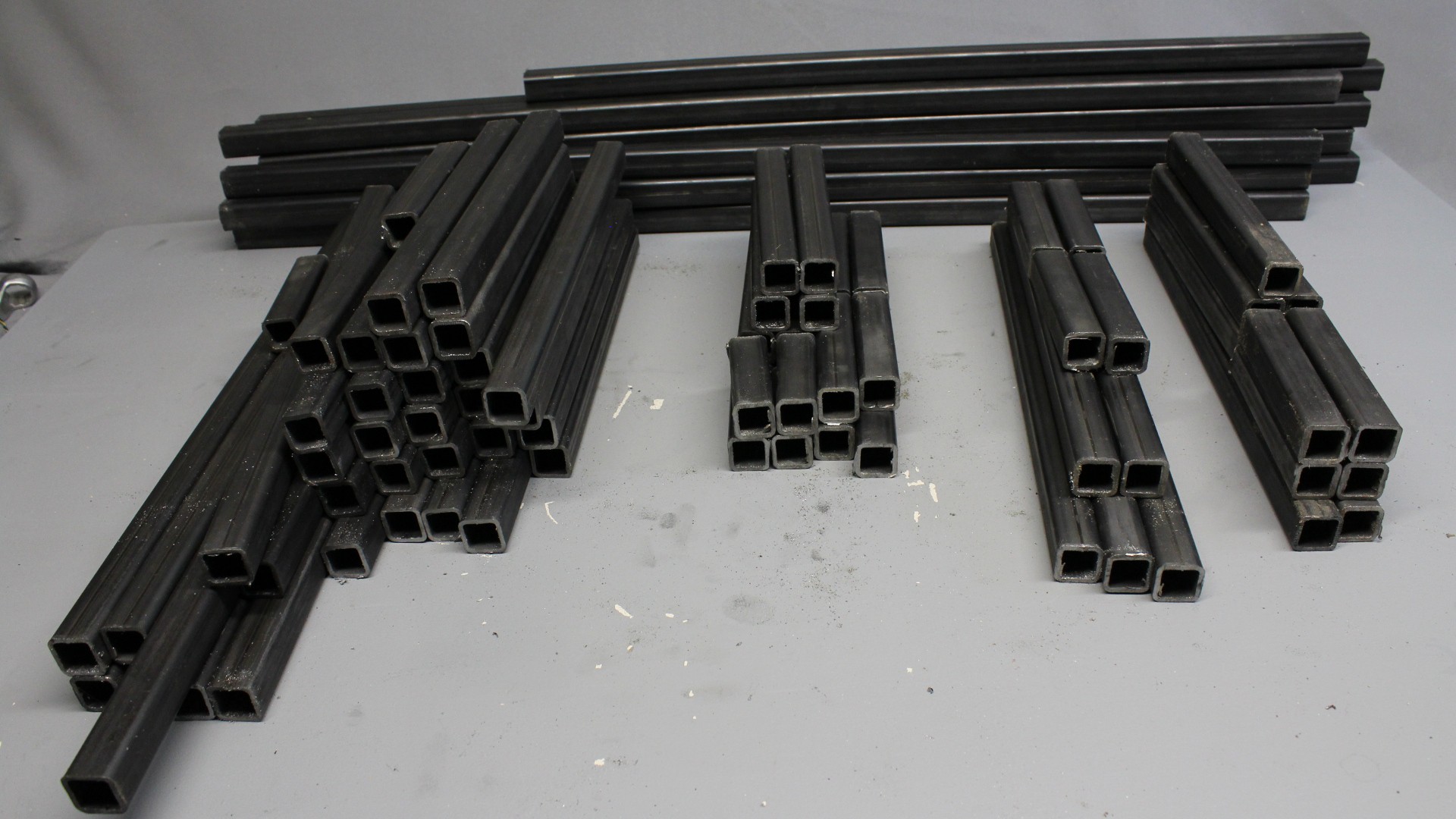
In endless hours I have cut square tubes (16 pieces 20x20x2x2000mm) for the framework:
![]()
After drilling, threading and finally putting some parts together, it looks like this:
![]()
I need a larger photo studio...
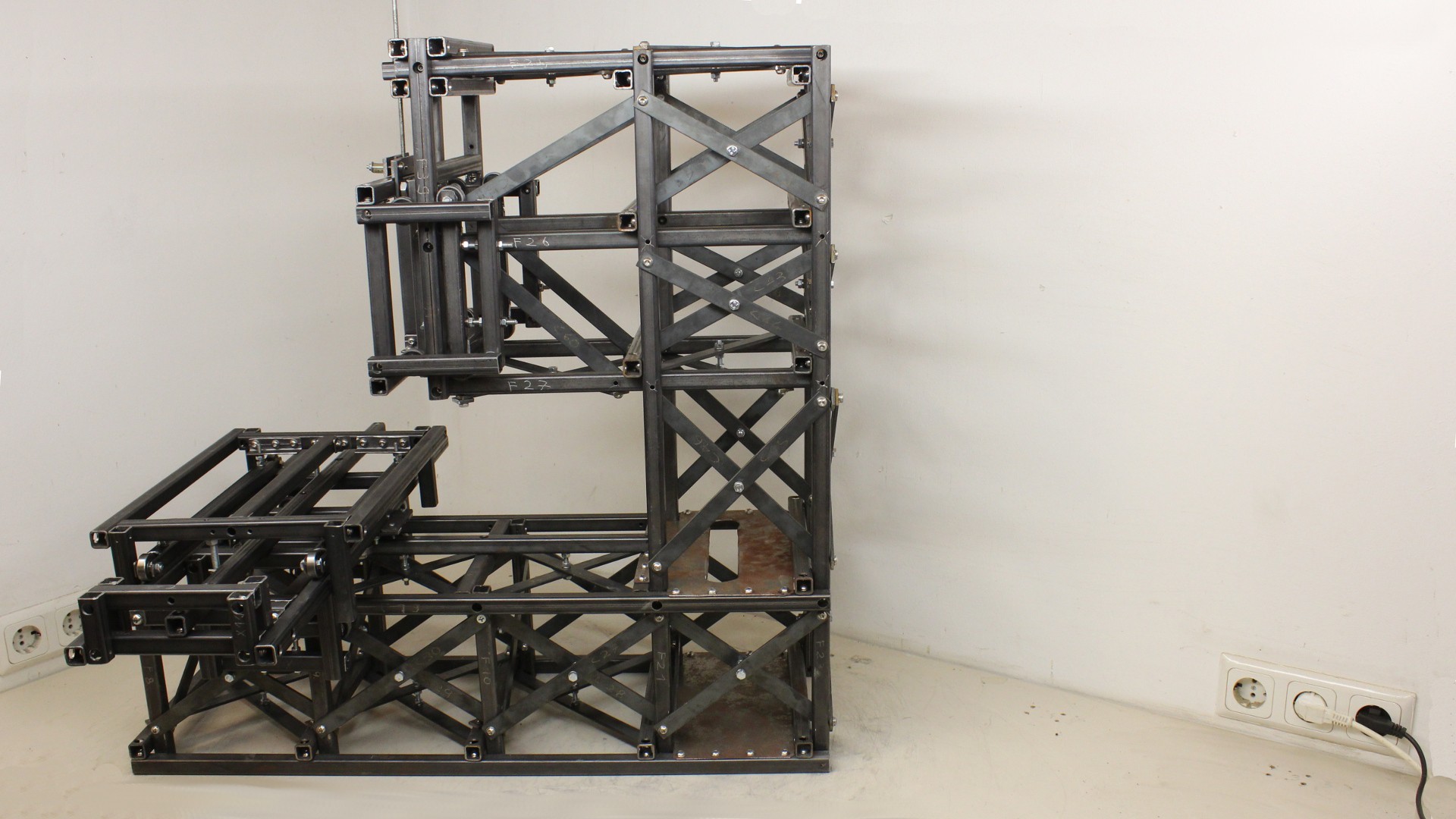
Next thing to be done is adding cross bars for higher stiffness of the base frame (CNC machines never can be stiff enough) as shown in the latest OpenSCAD file:
![]()
I am waiting for the flat iron bars to arrive...
-
Automation? Manual work comes first!
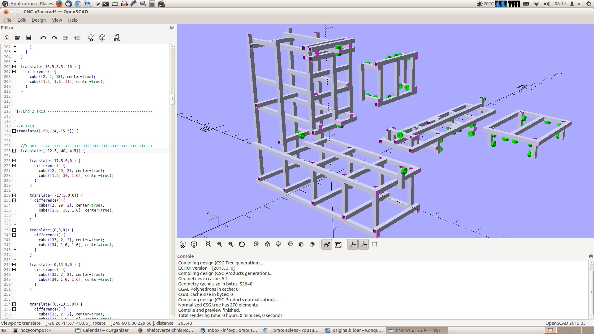
07/26/2016 at 07:13 • 0 commentsTime to build the mechanics of my CNC v3.x router. It's the first time ever I was using CAD software. The program of my choice is OpenSCAD, because I like typing source code rather than clicking with my mouse. The frame is made basically using 20x20mm steel square tubes:
![]()
With OpenSCAD I could quickly set the dimensions of the square tubes and prove if the carriages won't stuck on machine parts. It doesn't show how stiff the construction is. I will add struts and panellings where needed. The linkages are also not part of the OpenSCAD file. I will use screws and nuts of the dimensions 6mm and 4mm to join all parts.
45 ball bearings make it all run smoothly.
A CNC router is the mother of automation, but the first machine must be build without a CNC. Since the main idea of the CNC v3.x series is to keep it simple, nothing but a drill press, a vice, a hacksaw, taps, screwdriver and wrenches are needed to create the framework - no 3D printer, no CNC milled parts and no lathe.
-
Motion sensing with optical mice
07/21/2016 at 15:01 • 0 commentsOptical computer mice have a resolution of 12000DPI, giving a pulse each 2µm in theory. What it is like in practice shows my video:
More results of my test series are available on my project page:
http://homofaciens.de/technics-machines-cnc-v3-x_ge_navion.htm
Computer mice are Human Input Devices rather than linear sensors for CNCs. There is more Citizen Science to come during the build process of my "CNC for 194 countries"...
-
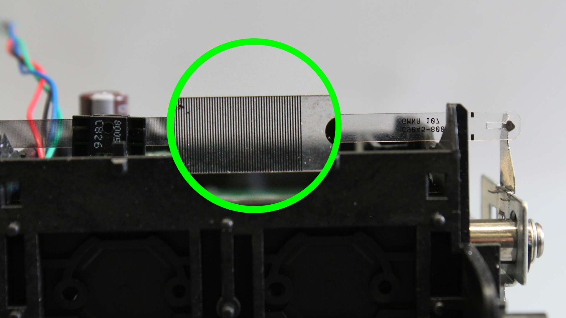
Using the sensor stripe of an old ink jet printer to detect motion
07/16/2016 at 11:15 • 0 commentsAnother video showing some results of my science weeks of this year's HackadayPrize:
The resolution of the sensor stripe I used in the video is 42 micrometers, thus we get approximately 580 sensor pulses per Inch at the Arduino. The resolution of the sensor disc (32 teeth) on the threaded rod as shown in the previous video is around 10 micrometers, thus it is clearly better. However there are some advantages in using a linear sensor.
-
More science to come
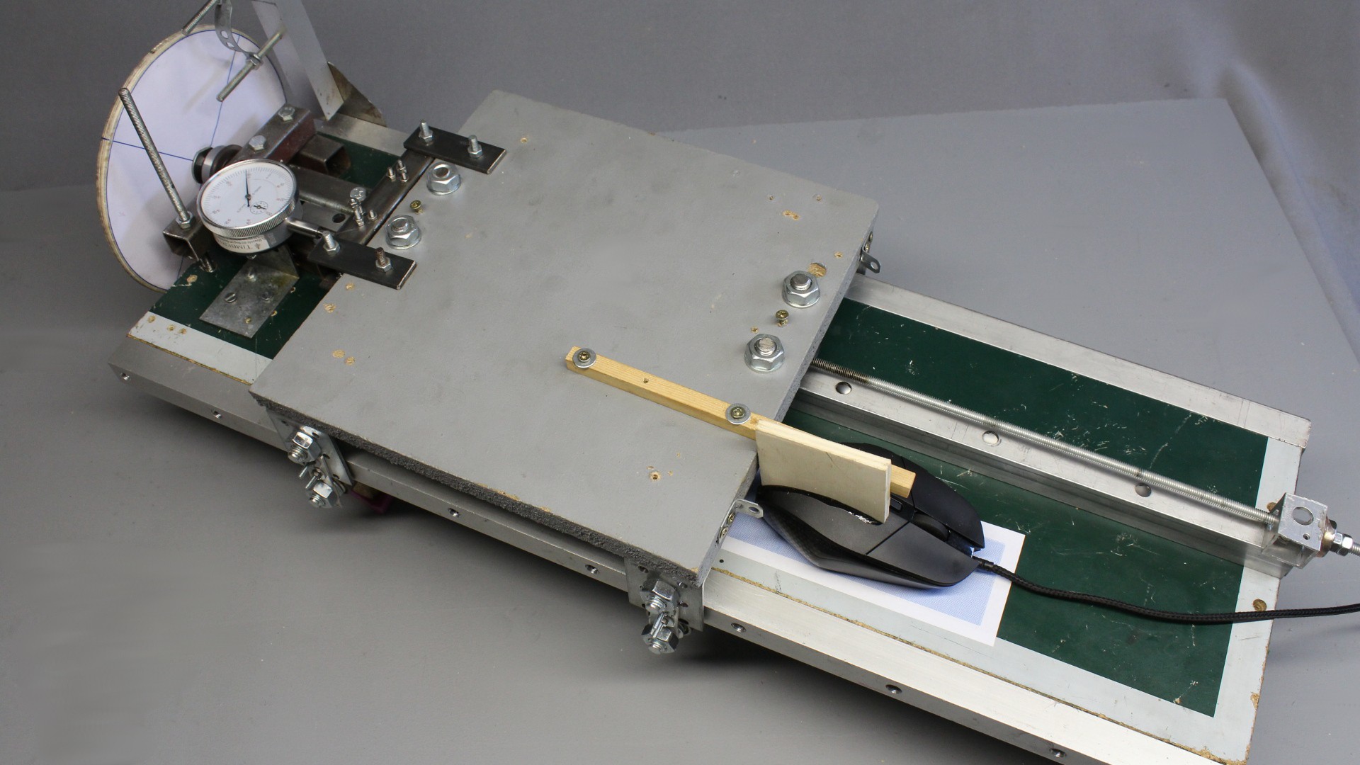
07/11/2016 at 08:37 • 0 commentsNow that I have a measurement setup, I am doing some more experiments with an optical mouse as linear sensor:
![]()
Another question will be how precise the linear sensors of printers are and so if they can be used in a CNC router:
![]()
The "Citizen scientist" campaign of this years HackadayPrize ends today, but that doesn't mean science ends, too. Hopefully I can give you the results until end of this week.
-
Accuracy of my DIY linear drive
07/09/2016 at 20:48 • 1 commentAfter hours, days and weeks of testing, modifying and testing again, the results are in this video:
I am still behind the timeline marked by this years HackadayPrize (which really pushes me...), but the results I got so far should really help to improve the design of my CNC v3.x series.The plastics thread linkage is the best drive I have built to date. Looks like science isn't a bad approach to get better machines ;-)
Self replicating CNC for 194 (or more) countries
Creating a design for a CNC that is easy to replicate and suitable for diverse drives.