-
Now talking to io.adafruit.com
11/11/2016 at 04:54 • 0 commentsI decided to add MQTT messaging to io.adafruit.com to create a couple publicly available dashboards.
When I changed the code to add the Adafruit dashboards, I updated some libraries which led to no end of fun. Long story short, one sensor was sending data to pin 2 on the Huzzah. The updated libraries broke this. When I tested, I assumed my terrible build quality had created the problem. Much testing later, I solved the problem by moving the sensor to pin 12.
There are now two public dashboards:
a week's worth of graphical data
and
The current (within ~30 minutes) readings.
The updated code has been pushed to my the master branch of my github repository.
-
Just Because I Build Ugly, Doesn't Mean You Should, Too
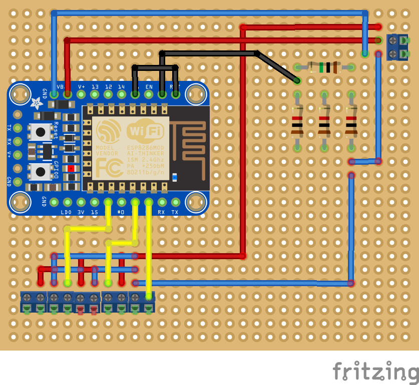
08/30/2016 at 22:11 • 0 commentsFor those interested, here's a Fritzing approximating my build. It doesn't show all the back-of-the-board solder connections or the twin rows of headers for mounting the breakout board. It also shows 5x2pin screw terminal blocks for the DHT22s instead of the 3x3pin terminal blocks I really used.
The voltage divider upper right is wired in series on the underside of the board as is just about everything wired in parallel.
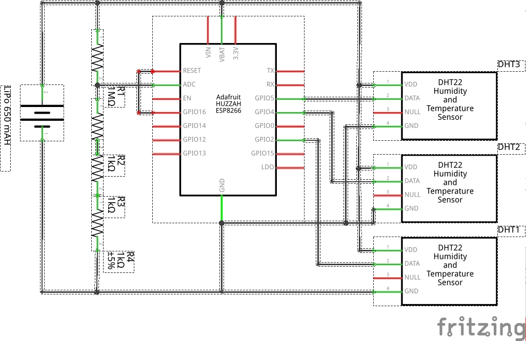
Here's a schematic showing how simple it really is. My Fritzing-fu is weak but I think it's readable.
- GPIO16 is jumpered to RESET to allow for sleeping
- The voltage divider limits the input to the ADC to a bit less than one volt
- The DTH22s are connected to battery power and ground. Next time I'll connecting them to 3.3V out on the breakout board
- DHT22 signal pins are connected to GPIO2, GPIO4, and GPIO5,
The code is the more interesting part of this but that's for a different log entry.
-
Quick and Dirty Solar Charger
08/30/2016 at 15:44 • 0 commentsThis sort of approach is all over the interwebs so I won't belabor it.
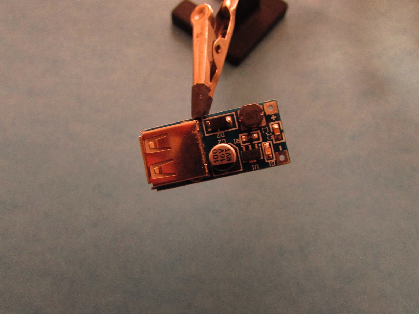
I wanted the data collector and reporter to be solar powered so I grabbed a DC/DC converter and a charger from Aliexpress. Both had USB connectors so a stubby little USB cable made it a trivial task.
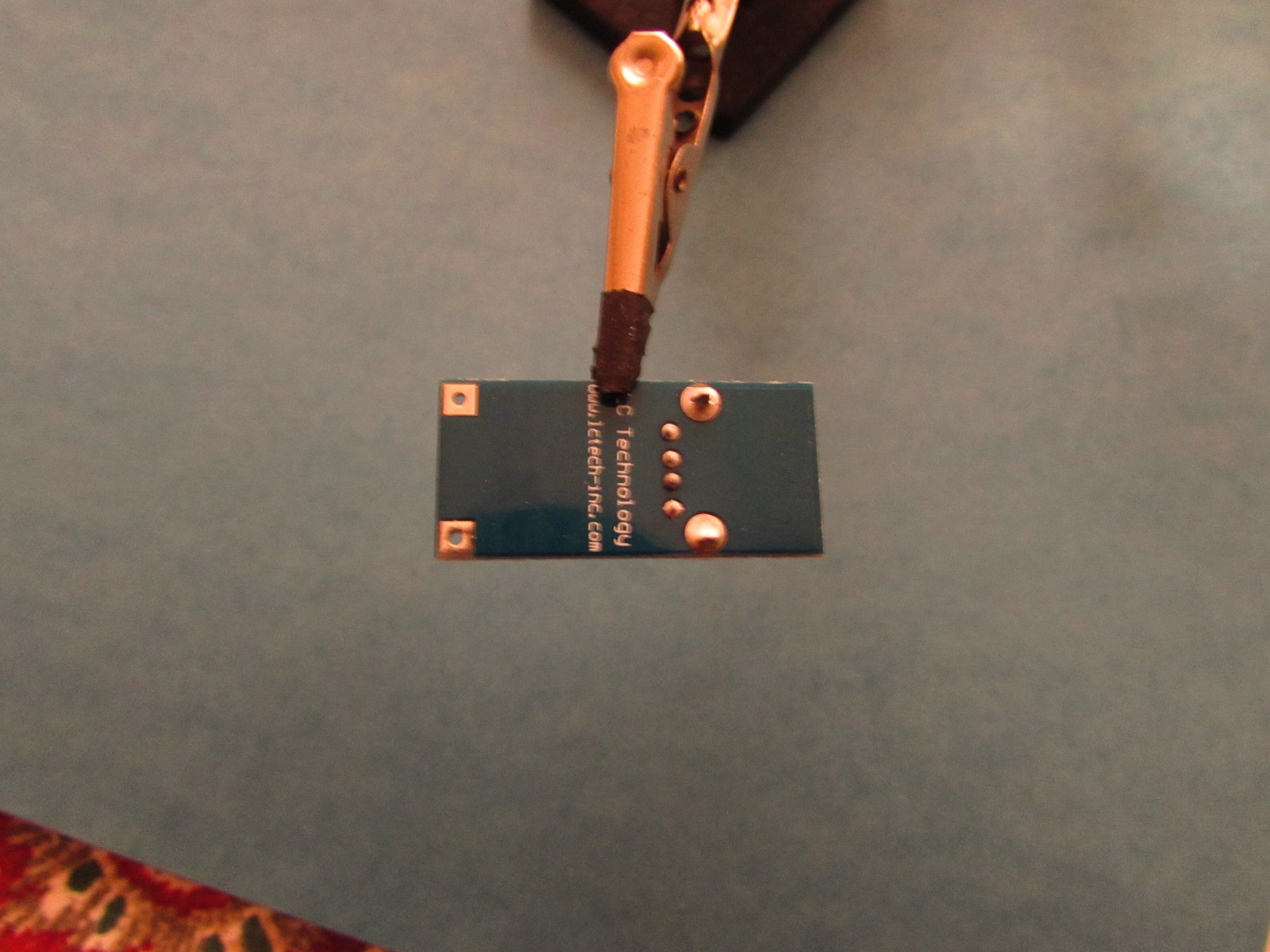
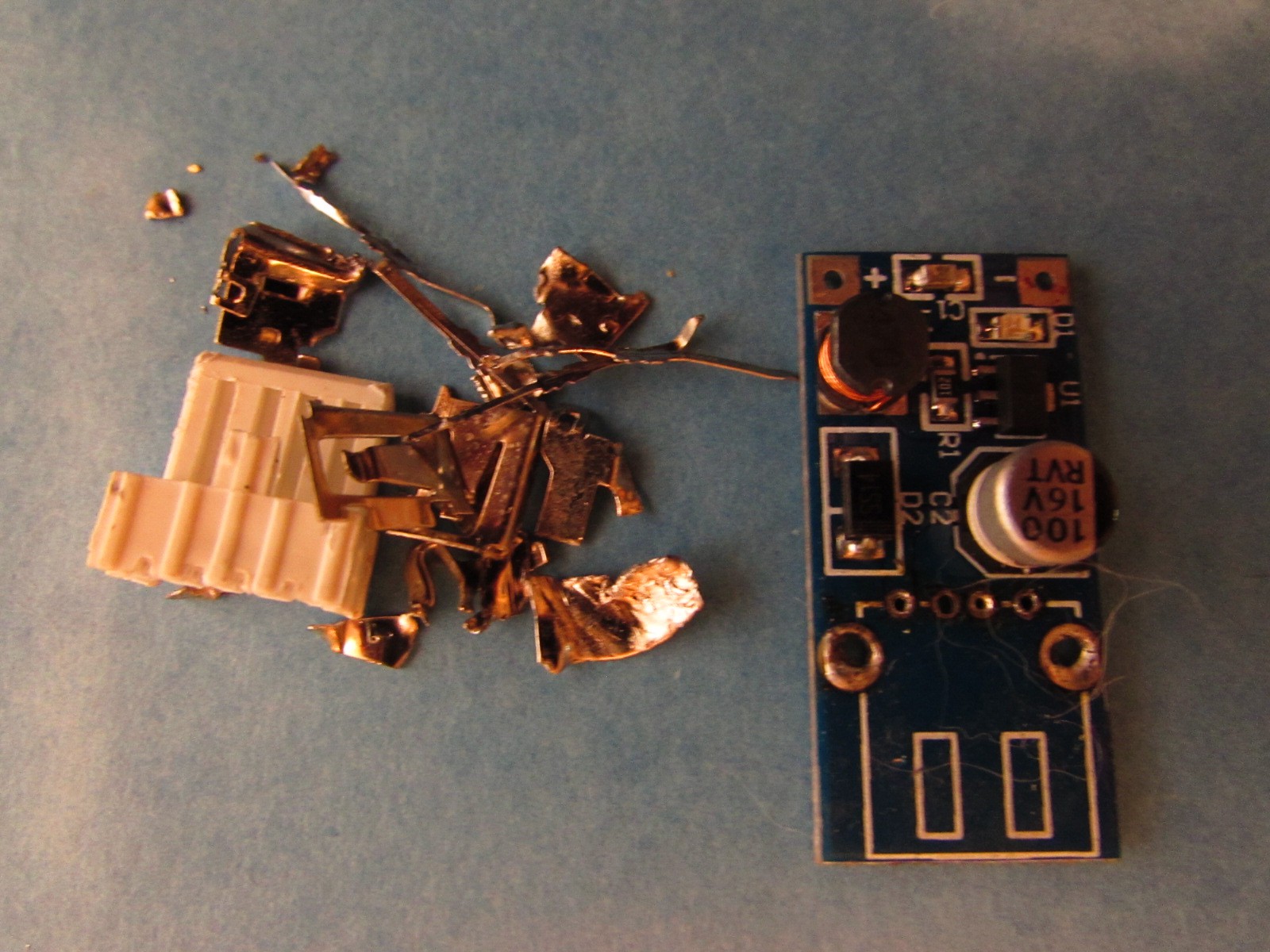
But trivial isn't fun and I didn't want to sacrifice a cable so i deconstructed the USB on the converter, desoldered the pins and soldered connecting wires to the charger.
A happy little fellow with a great big USB connector.
It's the top and bottom pins of that row of four I want to expose.
And so I did. Tearing stuff apart is my strongest hacker skill.
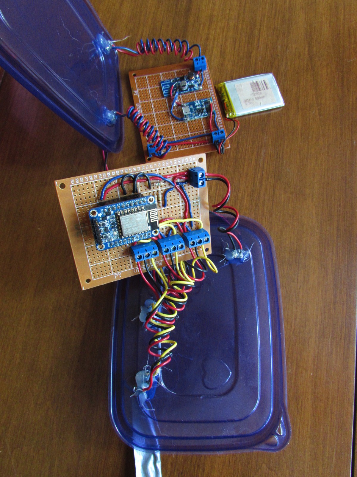
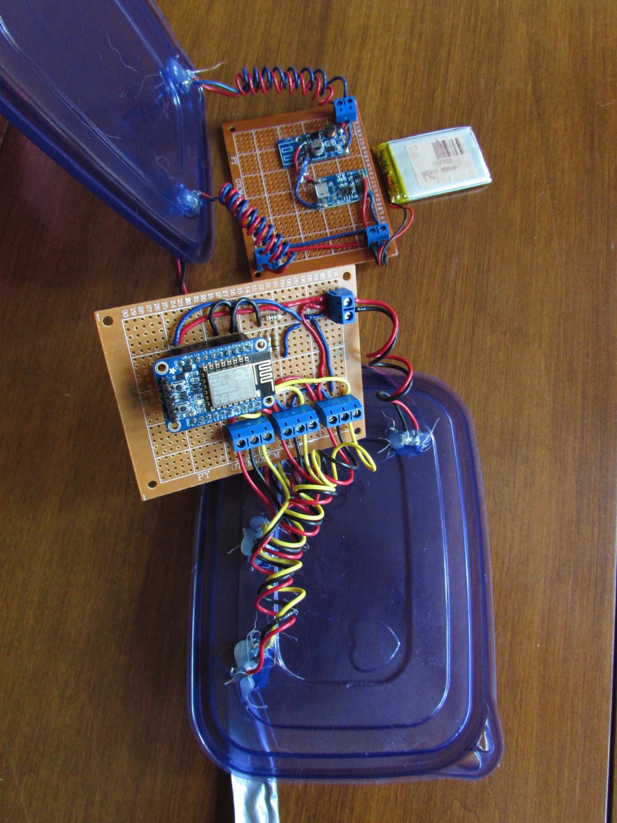
A little perf board, a little hot melt glue, a couple connectors and here's the charger circuit.
It's the top chunk of perf board in this picture, connected to the LiPo and ready to be stuffed into its weatherproof enclosure /sandwich box and connected to the solar panel.
-
It's working with the Adafruit Huzzah ESP8266 Board
08/30/2016 at 14:55 • 0 commentsLots to update. Let's start with the change of ESP8266 boards. It's relatively inexpensive ($10 US) and draws almost no power in deep sleep mode. In the image below, you can see it plugged into a couple rows of headers that are soldered to the relevant pins.
- VCC to the battery
- GND to the battery
- ADC though a voltage divider 1MR | 3kR
- Pin 16 jumpered to RST for sleep mode
- D2 D4 and D5 connected to signal from the three DHT22s
- DHT22 Power connected to battery (they only draw 50 nano Amps when sleeping).
Next iteration will connect them to 3.3V out on the ESP8266.
-
Switched to Adafruit HuzzahESP8266 and solar powered
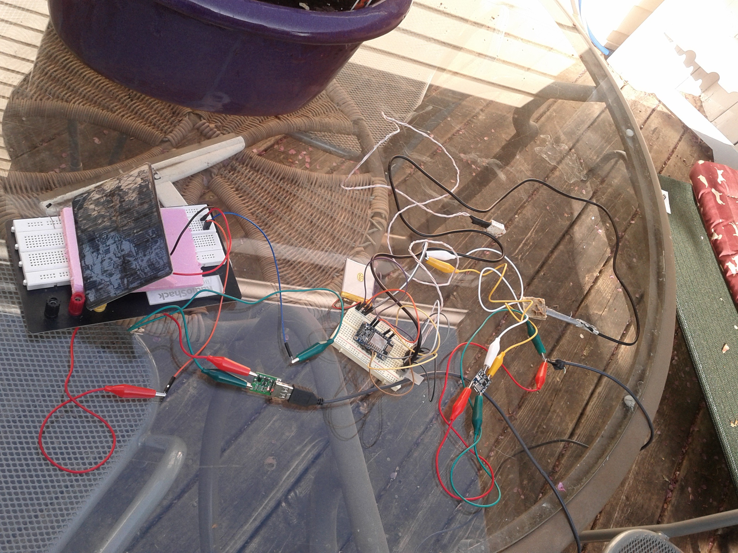
05/20/2016 at 14:12 • 0 commentsYou may see an ugly mess of wires and stuff. I see a solar powered Adafruit HuzzahESP8266 reading data from two DHT22 temp and humidity sensors and sending the data to an MQTT broker in my secret lair.
The adafruit HuzzahESP2866 breakout board seems delightfully efficient. I fully charged a 3.7V 650mAH lipo and let it run for three days. I didn't measure power draw but after 72 hours without a fault, the battery showed 4.0V. I'm using deep sleep mode and waking every hour (approximately) to sense and communicate. The rig in the picture is 5V solar panel => 5V voltage regulator => battery charger => lipo + ESP2866. The DHT22s are powered from 3V out on the ESP2866.
On a sunny day, I never saw the battery drop below 4V and it showed as fully charged after a couple hours. It partly discharged/recharged several times during the day and ran without fault overnight.
Over the weekend I'll weather-proof it a bit and test to failure (or June 5, whichever comes first). On June 5 I'm doing a split so the target hive will be open. I'll install sensors and mount the panel and power circuits. -
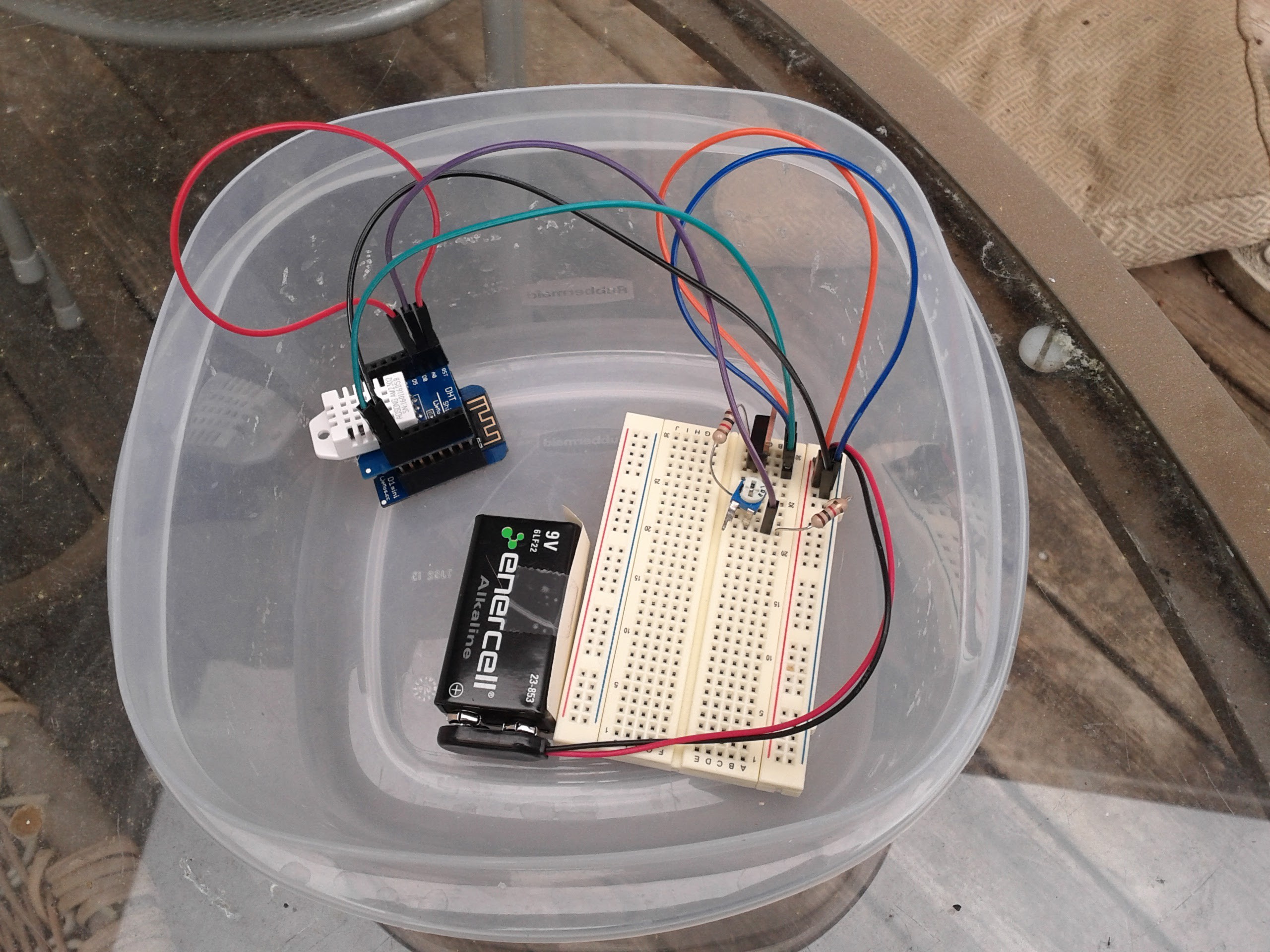
Doh! You can power the WeMos D1 Mini ESP8266 from the 5 Volt pin
04/22/2016 at 18:18 • 1 comment -
WeMos not the right ESP8266 for the job
04/02/2016 at 20:55 • 0 commentsThe WeMos D1 Mini only takes power from the USB port. I have an adafruit HUZZAH ESP8266 that has a couple Vin pins. I'll be switching over to that as soon as I solder some headers on.
-
Minor Refactoring
04/02/2016 at 20:55 • 0 commentsDid a little hygienic work to clean up the code, prep for monitoring battery voltage, and get credentials out of github. The only remaining branch is the master.
-
Software mostly working
04/01/2016 at 02:17 • 0 commentsI have software controlling the ESP8266 reading data from a DHT22 and sending it via MQTT to adafruit io. It's been working stably for over 24 hours. The code is on github at https://github.com/dgr-crenshaw/cyberHiveWiFi.git The powerManagement branch is the active code branch.
Beehive Monitoring, Now With WiFi
Using a WeMos ESP8266 D1 Mini and DHT22 Shield to monitor beehive temperature and humidity
 Don R-Crenshaw