 [skaarj]
-
Test Example Post: Mainframes behind the Iron Curtain
12/03/2016 at 17:09 • 0 commentsDecember 3rd, 2016 by [skaarj]
![]()
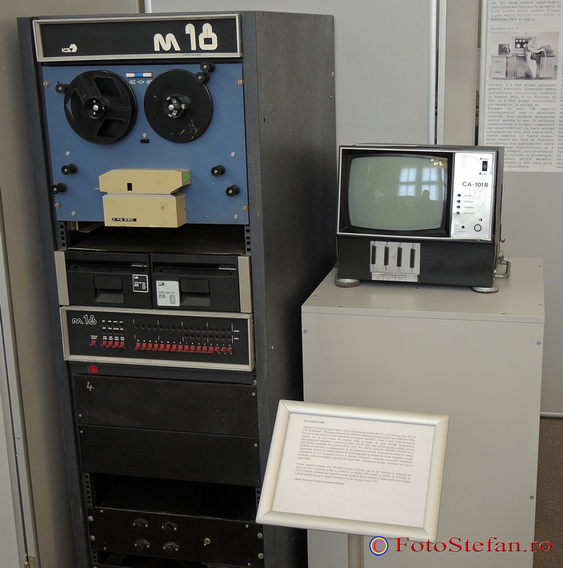
We've covered a very small number of topics about computing technology behind the Iron Curtain, so here is a fresh hot one: [skaarj] is rebuilding a Romanian Mainframe (translated link). Such pieces of communist technology are pretty rare and most of them require excruciating painful hard work to resuscitate. [skaarj] is not entirely sure which mainframe type to chose from the three dinosaurs roaring in Romania's computing centers during those dark prehistoric times: FELIX, CORAL or INDEPENDENT, as the components are pretty rare, in very bad shape and whatever parts he managed to salvage... come from all three types. Due to their proven performances, those three names were a shock for the COMECON market controlled by the Soviet Union, so Big Uncle Bear officially restricted any exports through special directives straight from Moscow. Some government sources explained the decision to Romania's beloved leader due to CORAL and INDEPENDENT being far superior to the USA's PDP.
So far [skaarj] managed to recover three racks from a Felix-type mainframe, some parts from a CORAL 4030 mainframe, a broken tape drive from an Independent i-100, a Siemens Sinumerik punched paper tape reader from a Felix-M18 and some various peripherals such as 8" floppy drives, huge hard disks, cassette tape drives or various circuit boards. The clumsy serial terminal called DAF-2020 (Display Alpha Numeric) is already up and running, and through the courtesy of [Nico] the future mainframe will be able to access PERTEC-interfaced peripherals through a PERTEC to SCSI converter.
Since the central processing unit (drawer) released its magic smoke in the final agonizing days of the communist regime while running a modified smuggled copy of RSX-11 Operating System, [skaarj] decided to hook a Marvell OpenRD Ultimate Development Platform and install FreeBSD Unix to get access to the functional peripherals and to experiment with ferite core memory banks. Check the videos after the break.
![]() Siemens re-branded StorageTek Industrial (PERTEC) interface tape drive
Siemens re-branded StorageTek Industrial (PERTEC) interface tape driveThe Romanian links are provided through Google Translator, as Language of Dracula slang is pretty hard to understand. Unfortunately, the Romanian Electronics Forum administrators changed the policies at the beginning of this week, requiring an account to view the attached pictures. [banner picture source: West Romania Museum-Muzeul Banatului, Timisoara]
We've covered a few topics about Iron Curtain Home Computers and Peripherals before, and we've also learned about those dark times from one of our most respectable hackers.
-
Project status: scrapped
11/03/2016 at 19:07 • 1 commentThe project has fulfilled its purposes but it did not caught the desired attention.
The automobile has a respectable age and it is a hard work to keep it running according to the security standards of the day.
In conclusion, probably at the beginning of the next year when the insurance expires, the whole system - automobile + accessories - will go straight to the scrap yard for material recycling. At least I will be able to recover a part of the investment spent so far to prove two very uninteresting subjects which were solved in my under-financed project:
1. Pollution emissions can be reduced using a simple approach, adaptable to most of the ignition and diesel engines;
2. Mechanical faults in automobiles can be prevented by means of artificial intelligence approach.
I will be back with pictures from the scrapping/crushing/recycling process - if I will not forget the camera inside the car.
-
Contest entry video uploaded
10/09/2016 at 21:50 • 0 commentsMade in a hurry to cover most of the topics presented in this project.
Later edit - enhanced quality + bonus - added night vision video
-
Assistive Technologies - Building cheap night-time vision goggles
09/14/2016 at 06:24 • 5 commentsFirst of all, we need two specialized vacuum tubes for amplifying the ambient light. Again, the Soviet Union legacy proves to be useful: V-8 tube.
![]()
B-8 (Cyrillic "B" in English it's V), made in May (5th month), year is 1981. There's also the manufacturer logo, probably some military factory, and also the manufacturer-issued serial number.
![]()
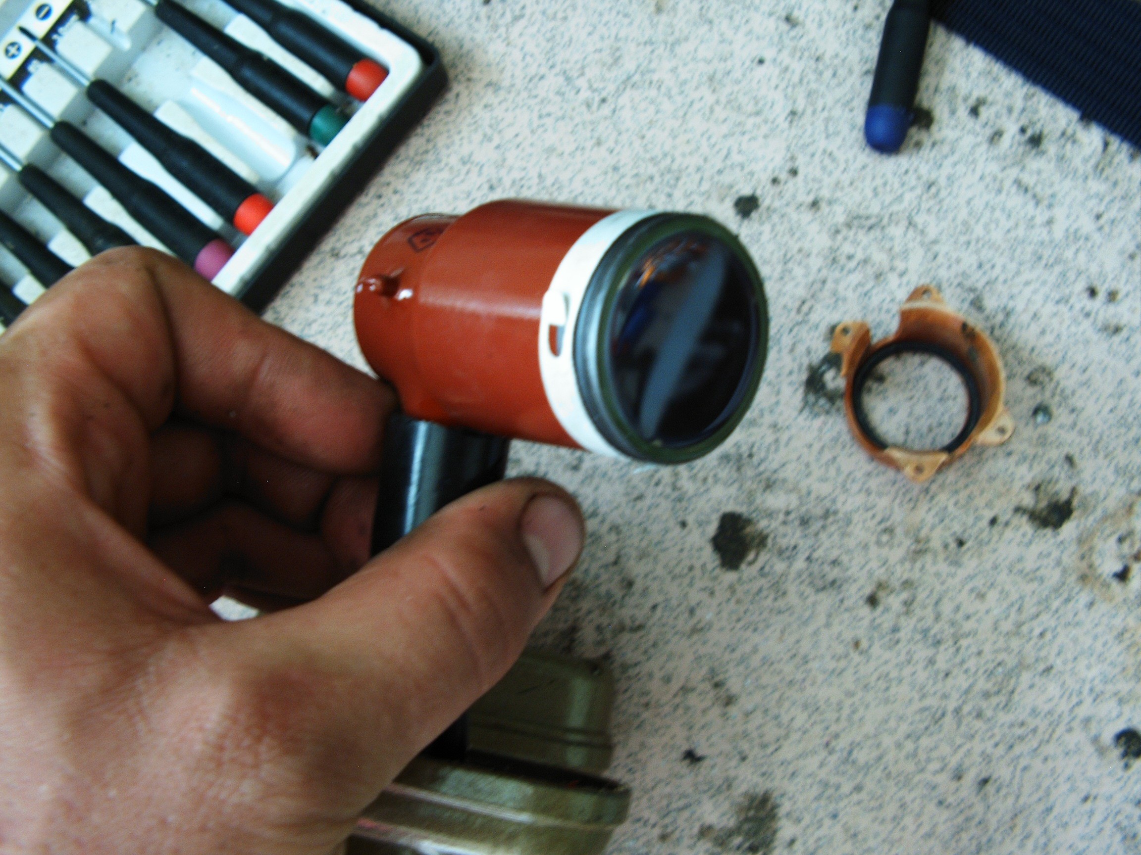
In front it's the light receiving window.
![]()
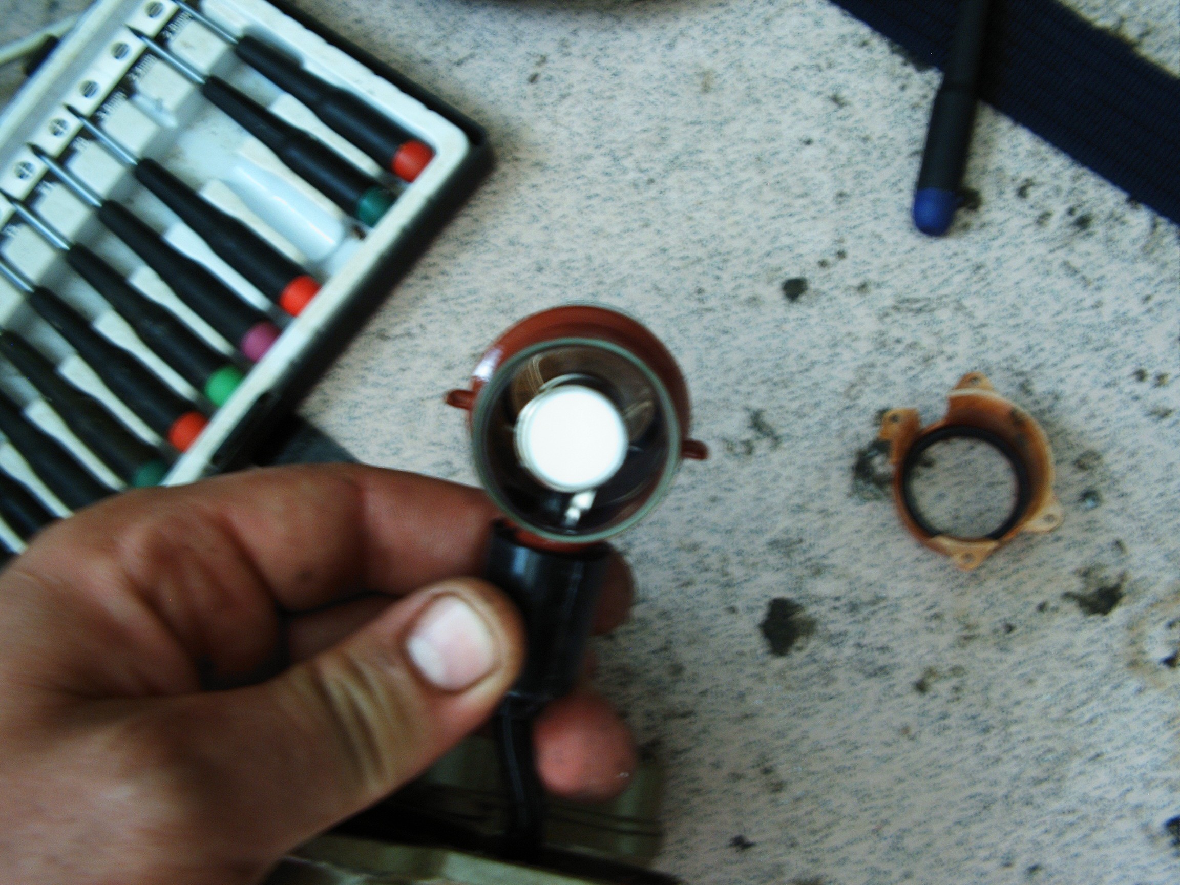
In the back side there's a phosphorus window which shows the intensified result.
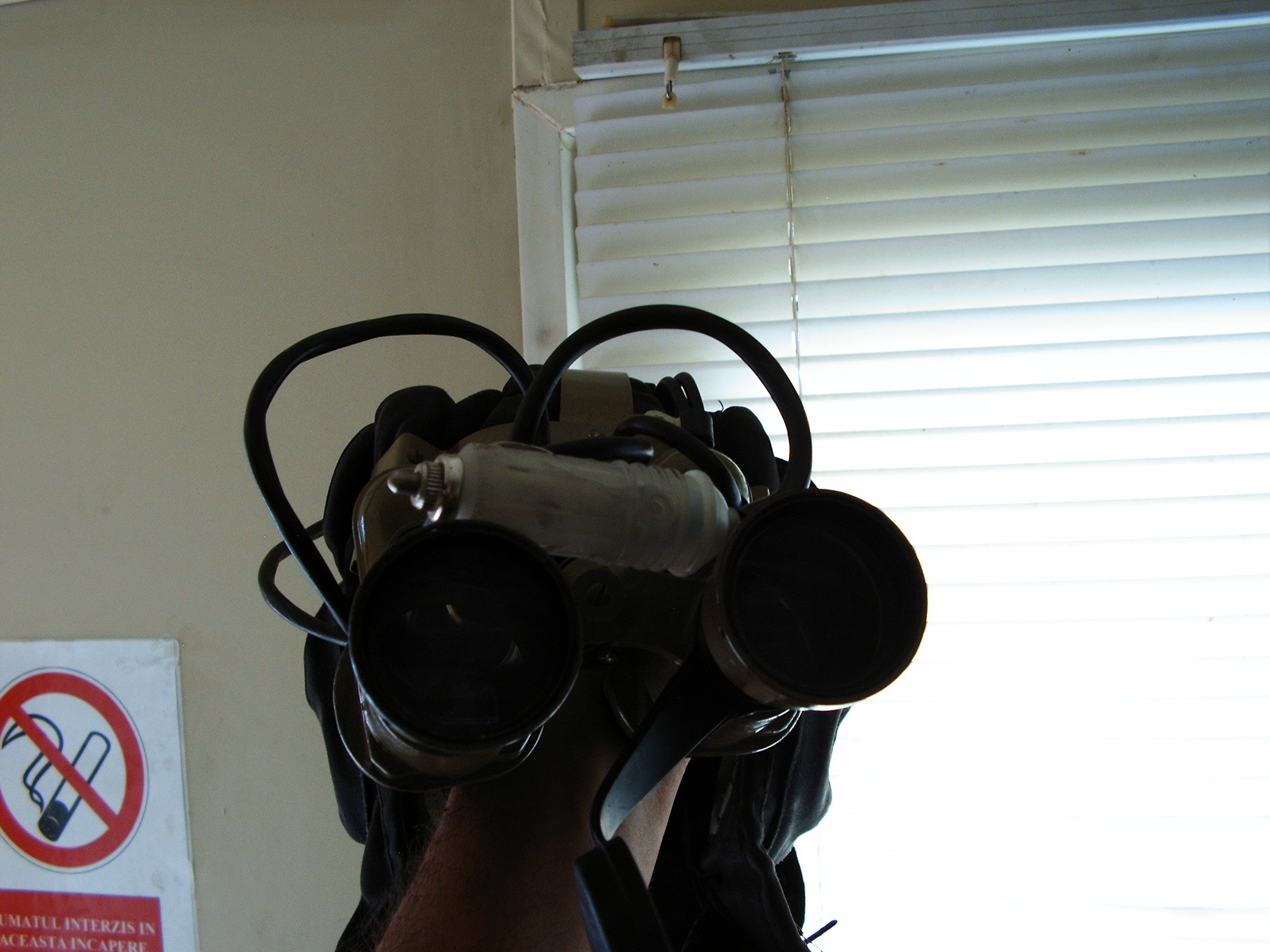
This is a 2nd generation light intensifier tube, one of the best available. We need two such devices, a toy binoculars and a helmet to install everything.
This tube has an anode (between the fingers) and a cathode which is located as a metal ring in the exterior. It must be powered at around 15kVolts to get the desired results.
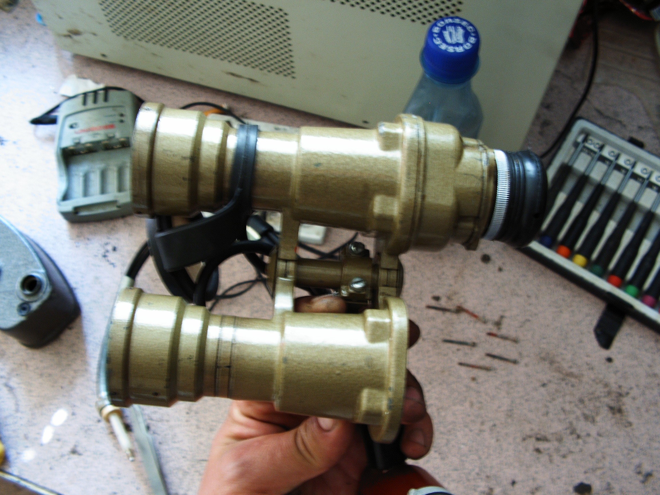
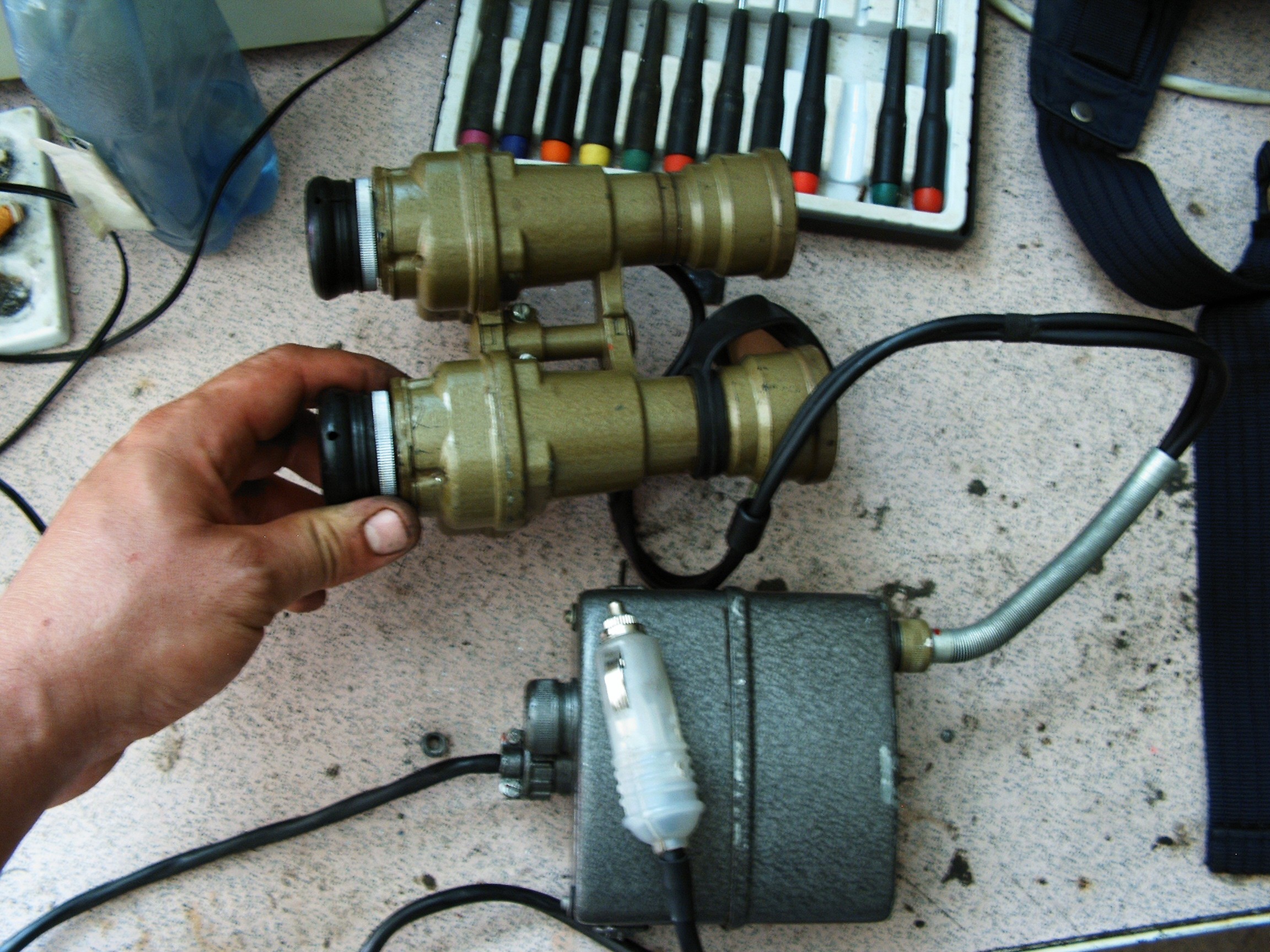
Binoculars:
![]()
Somehow I need to replace the prisms with the tubes, and this baby has a lot of space.
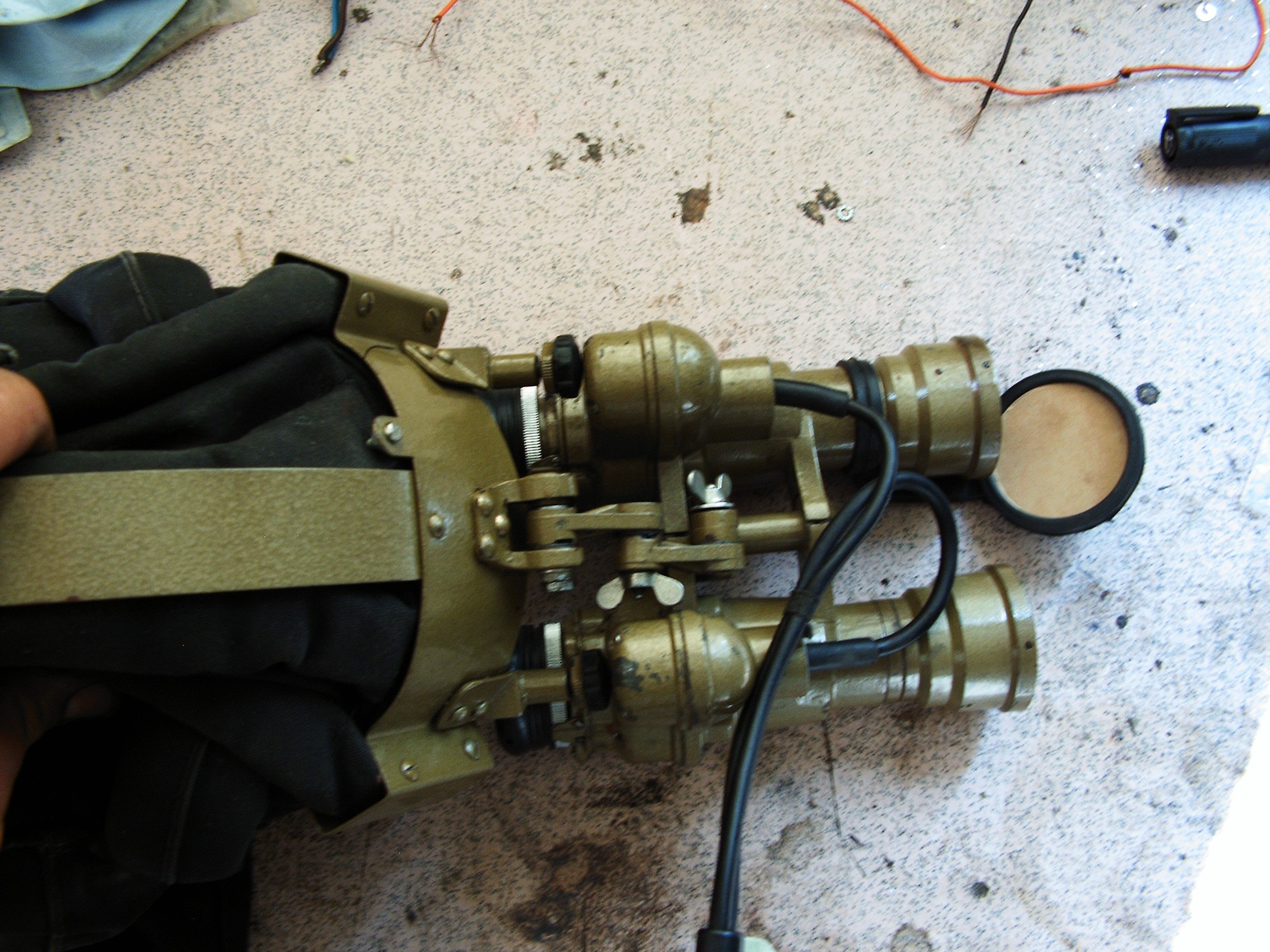
![]()
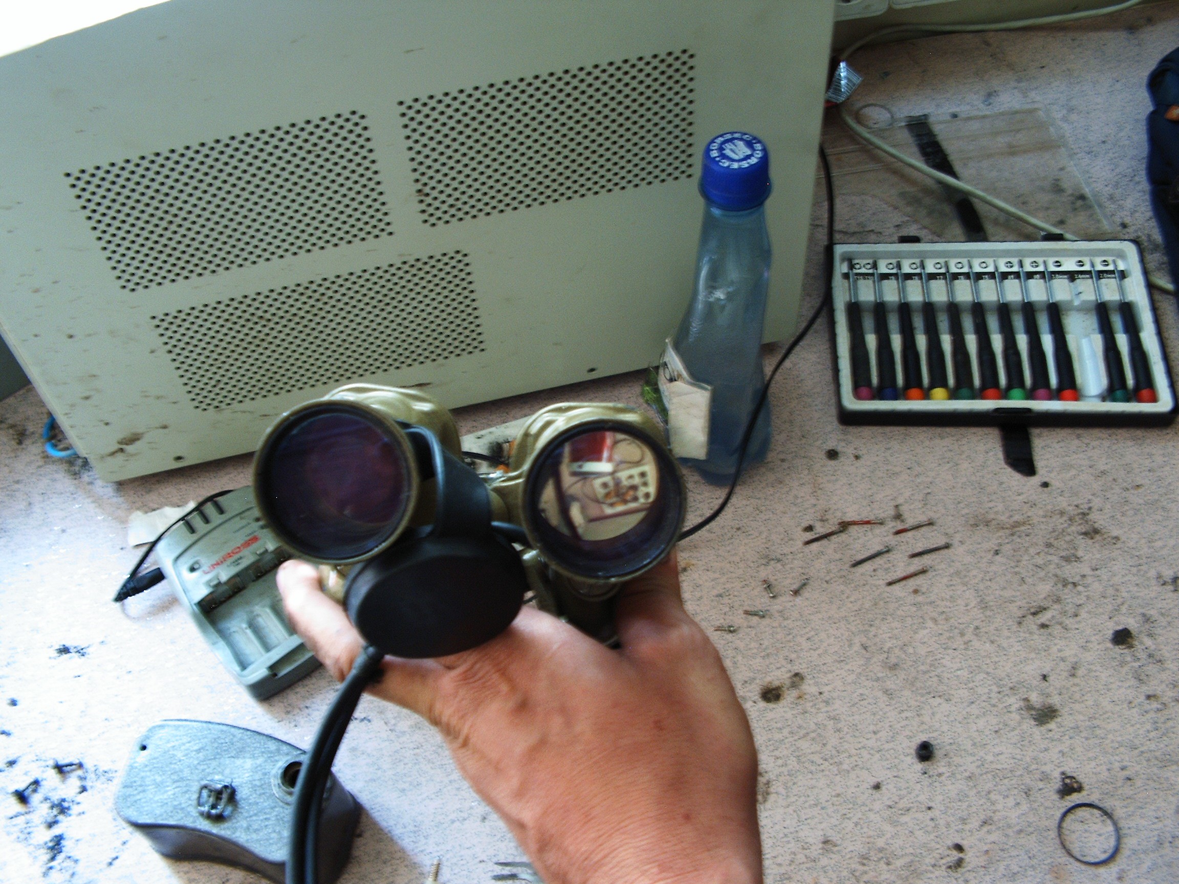
Left side tube is already installed. These details cover the right side install.
![]()
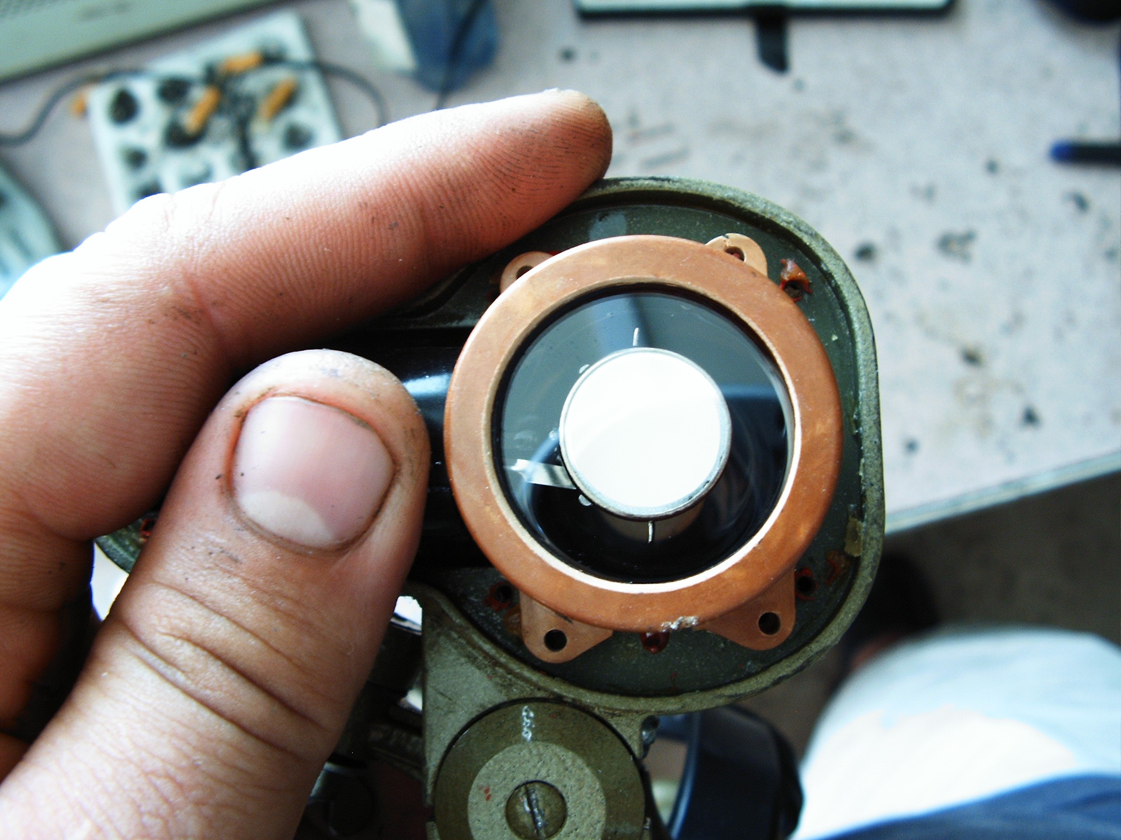
Protection ring comes with the tube - if acquired from military surplus source. Need to make 4 (four) holes, 2 millimeters in diameter. Phosphorus window is oriented to the eye lens.
![]()
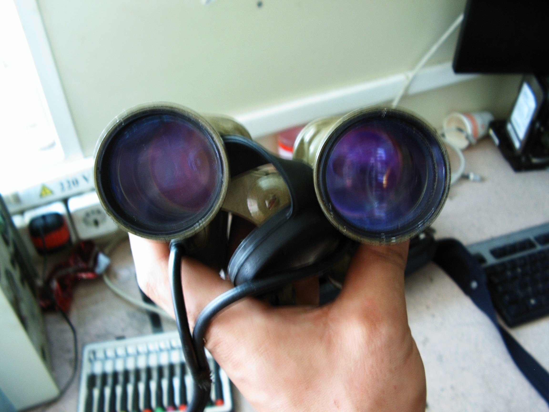
A little fine tuning of the lens distances will be performed after powering on the system.
In order to accomplish this, we must ask for help from the Soviet Union military surplus: two high voltage rectifying diodes and a transformer-based voltage converter, in order to power it from 12V (car lighter):
![]()
This is a classic single transistor, single transformer feedback oscillator.
![]()
Please excuse the dirt on my hands and on my desk. This is my work place laboratory, I'm currently performing some maintenance for some oil drilling pressure sensors. The dirt I handle in the oilfield is cleaner than the dirt they handle in the offices and I'm proud of that.
![]()
You are probably wondering why do I prefer this ancient converter instead of building a modern one with some microcontroller, a PWM output pin, some FET transistors and a small switching transformer.
![]()
First of all, this is insulated and protected from shock and moisture, including these two high voltage rectifying diodes.
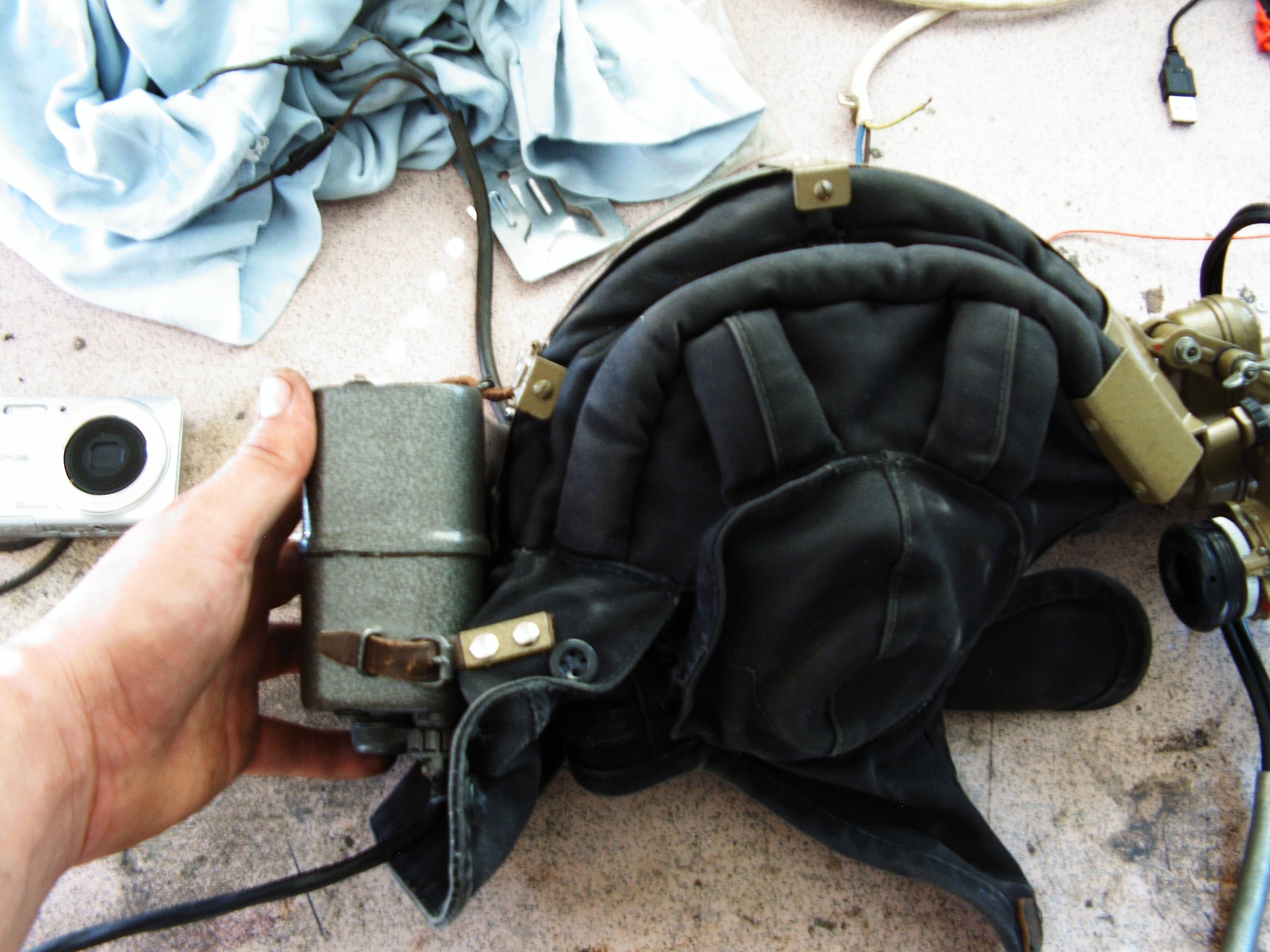
![]()
Second, I need this baby to balance the binoculars weight on the helmet: binoculars stay in front, converter in the back side.
![]()
I'm wearing the helmet while driving, this is stressful enough and I need the hands free of any additional tasks.
![]()
Helmet is also military surplus, used by tank crew in the old days. Keeps warm, it has earphones included and it can be "upgraded" with metal work.
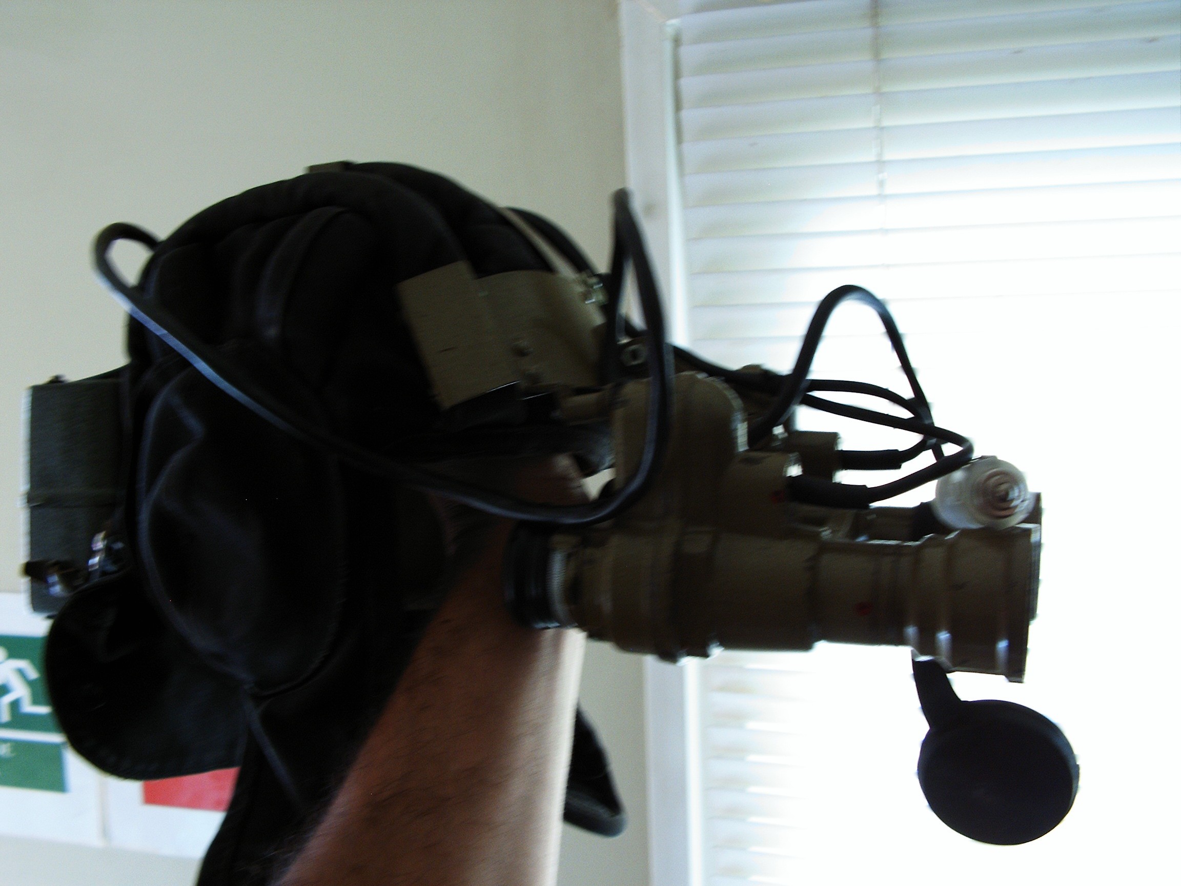
![]()
Helmet is balanced...
![]()
...and ready for final optic adjustments.
Night-time test drive:
This is raw video footage recorded with a Samsung Galaxy Trend Plus S7580 rear camera. It reacts weird to bright images, normally the picture is clear. Anyway, when brightness is low, the camera can capture/record the road and trees in clear.
Message for the feds/police: THE FOOTAGE IS RUNNING AT 2x PLAYBACK SPEED, I DID NOT DRIVE LIKE CRAZY!!!
In the mean time - if you decide to build this thing, you must be careful not to power it up in day light without covering the lens. You will burn the phosphorus windows and the tubes will become useless.
-
Assistive Technologies - Let's improve night time driving
08/23/2016 at 07:34 • 2 commentsAllright, I'll keep this short for now because I'm at work and boss will get very angry if I'm discovered writing a new log instead of watching the monitors while the antivirus is doing its job over the entire network.
As my colleagues from hack-chat already know, I went to Greece taking my princess for a test drive in May this year. I left Romania, I passed Bulgaria during night time and I arrived at Makaza-Komotini pass in the morning. Around 8 hours of driving in pitch dark in the Bulgarian mountains. Because I read all sort of weird news and reports in the newspapers, I decided to build (hack) a counter-measure to get there safe and also to get back in one piece. There are some gangs in Bulgaria which simulate a car accident or car malfunction, and ask people to stop and provide help. Basically you're driving, it's night, sometimes fog is present and there's this guy with a ramped car waving his hands desperately. You, a decent unsuspecting driver, decide to stop, come out of the car and offer to help. Five seconds later some more guys appear from a nearby forest with Kalashnikov guns pointed at your head. From this moment your life is on the table, Mafia is the poker dealer and the house has all lucky hands: you lose your car, your money, your phone, your daughter, your wife, your clothes, even your underwear. The ramp-jacked car also leaves and if you are lucky, they let you barely alive. Broken bones are mandatory.
How can you avoid such incidents?
You need some help provided by Assistive Technology. You need to see them from far away. You need to see the road as clear as possible to avoid any other nasty stuff such as pieces of wood with nails or spike strips to blow all your tires. You don't need to win the round. You need to survive and to keep your family safe.
When I returned from Greece one week later, I saw some guy with a stopped car and the spare wheel near it. He waved his hands at me. Behind some trees, my googles informed me there were more people, so I kept going and informed the Police.
I will be back with building details.
In the mean time follow my advice: don't waste your sleep() time. It does bad things to your heart.
[END OF TRANSMISSION]
-
Automation: let's build this!
07/15/2016 at 04:40 • 4 commentsUnable to comply.
The hard work done until this time was not recognized and not acknowledged so far [not even as blog articles] and will never be. There are other projects artificially enforced to be liked and followed. Small steps on the hard road of science - as an example: trying to reduce lung cancer - are considered to be less important and are better ignored - enforcing political correctness tactic. Occult worship such as Pokemon Go is the important subject these days.
Fatal error: finance reserves below zero.
System halted.
______________________________________
kernel panic: improbability coefficient below zero
-
Artificial Neural Network-based Mechanical Faults Diagnosis (III) - Vibration detection test
07/08/2016 at 10:25 • 0 commentsGreetings, fellow hackers.
Big news: the hardware ANN speech recognition chip was fried during one of the many storms sweeping my area. No more chances to get another one in time for the round finish. Previous work with denied access to normal equipment lead to reviving a piece of junk to perform exhaust measurements with strange results, including magic smoke. ANN is now fried. This means I'm already disqualified from the Citizen Scientist round, no need to wait for the results.
This chip can be found at Images Scientific Instruments in the US. It's expansive and customs taxes to bring it to Europe makes it unaffordable for the moment. Also, even if it arrives here the next day, the customs will keep the package for another one to two weeks due to bureaucracy. No chance to get experimental results in time for round finish.
It worked the first time and the experimental results were already presented here as a scientific academic paper. It should work in this experiment without any problem. We'll see. My [WWK] (without wife's knowledge) funds are depleted, no chance to get another one. Under current conditions, not this year for sure. But I don't worry because nobody cares about that anyway.
This system can be successfully used to acquire data for a certain type of automobile to identify bad mechanical components by deliberately inserting malfunctioning parts in the wheel axles and also engine block (to get the desired training data) and learn from these situations to detect similar conditions. It can be used in automotive services to easily identify problems - or at least have a clue where the problem may be located. It can also be used by manufacturers who wish to study more about the behavior of their products. Or to understand the purring of your cat, the barking of your dogs, or whatever vibration-pattern-recognition idea you have in mind.
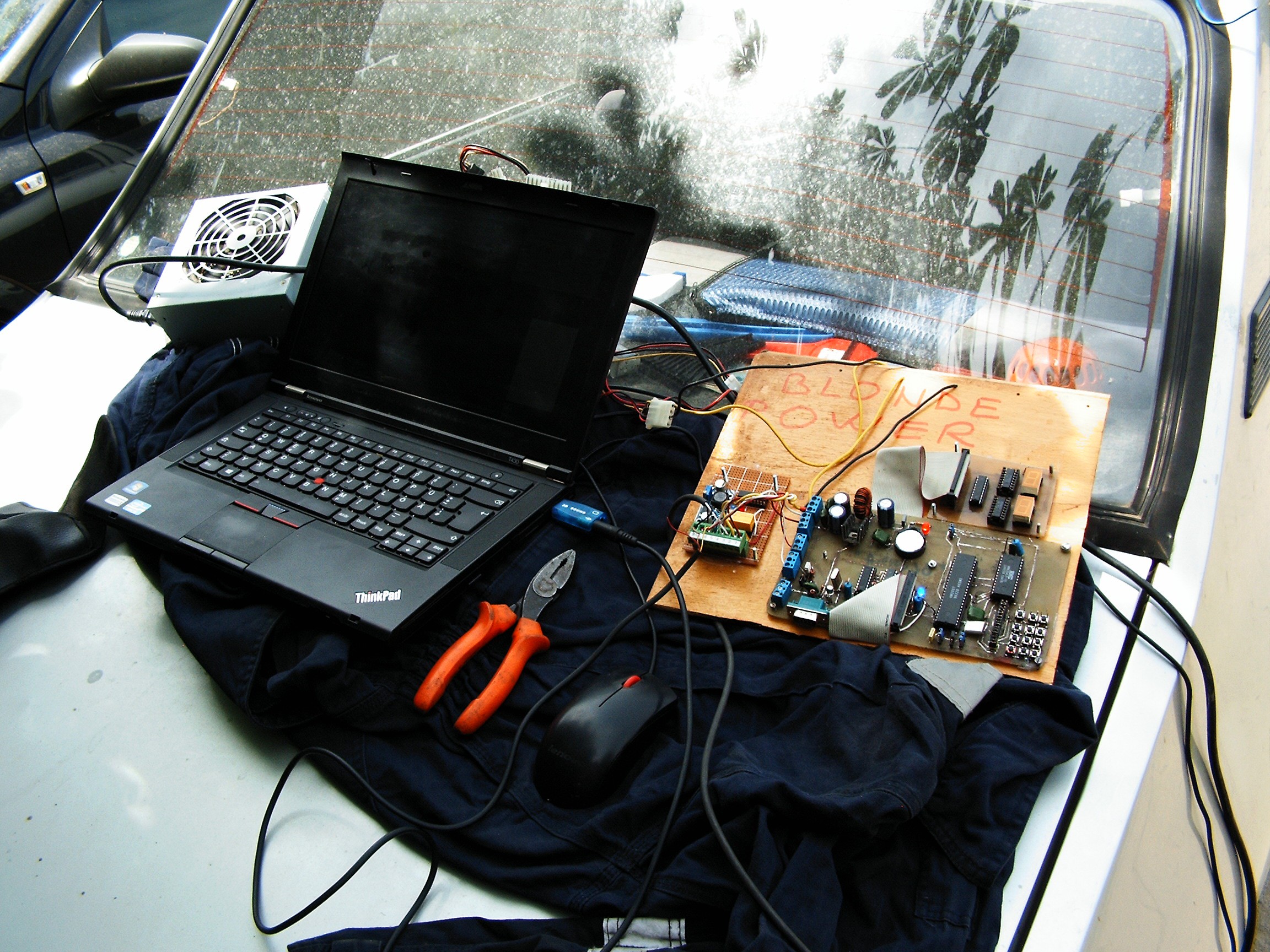
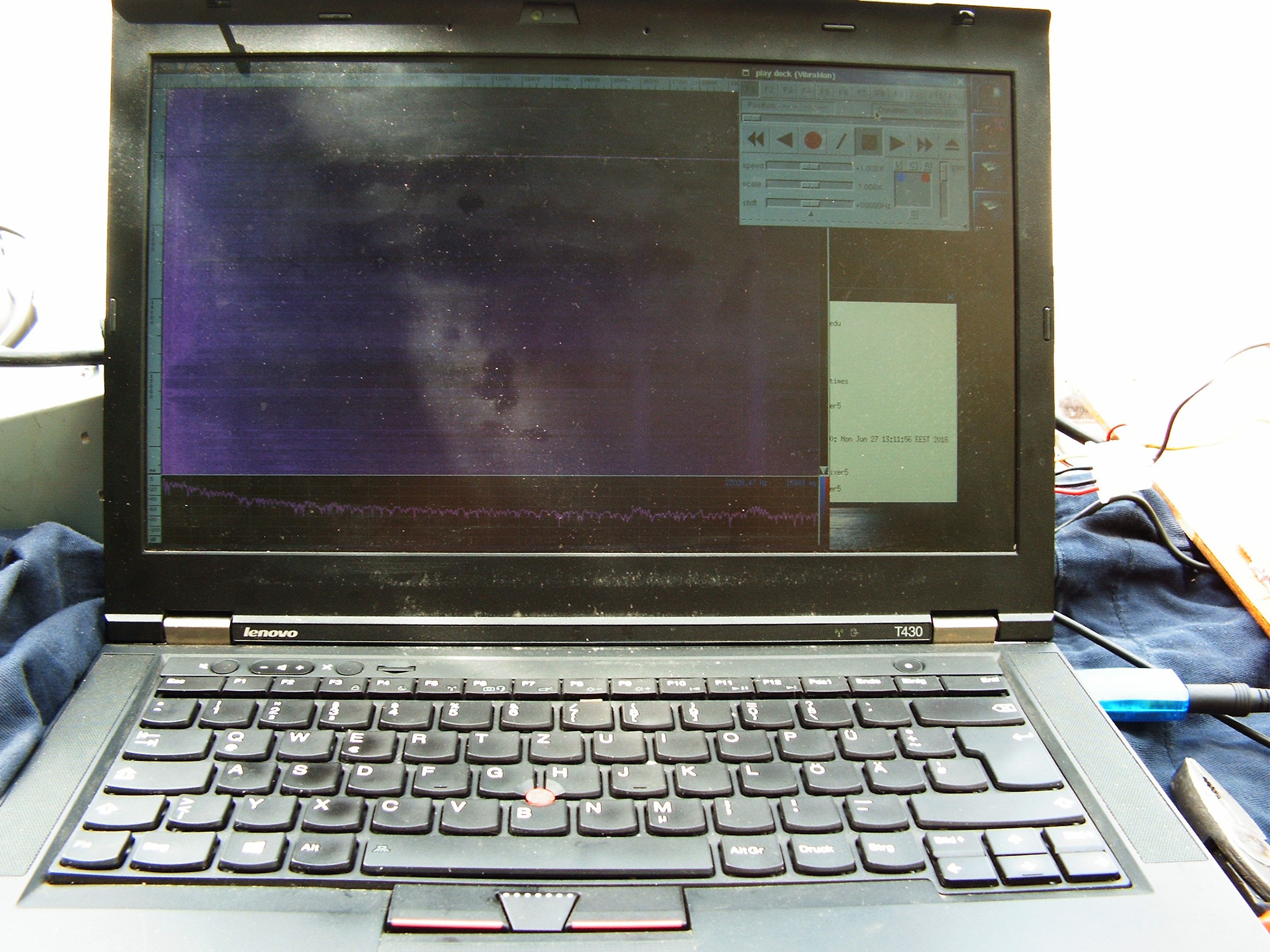
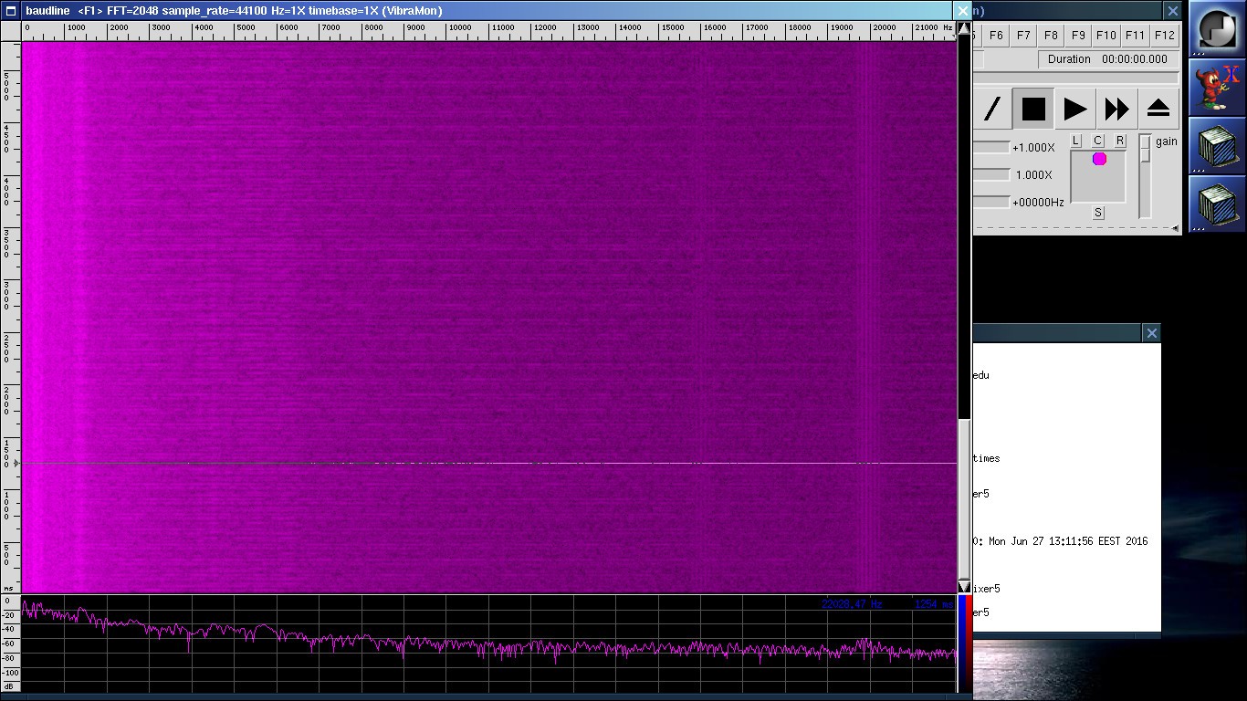
I only have the video in the bottom of the page - live vibration monitoring with baudline on the laptop screen.
Later in the video when the car is moving, you will see the ANN system boards. There are three leds showing activity:
- blue led and red led which alternate - located on the input switching board. When blue led is on, ANN chip input is connected to ADXL accelerometer. When red led is on, ANN chip input is connected to GND;
- blue led in the right side, near HM2007 ANN speech recognition chip: blinking confirmation light showing the ANN detected and processed the vibrations.
Numeric display shows some signs of instability - there's some bad soldered connection somewhere under the mainboard.
Thank you @ThunderSqueak for going through your electronics cache to find a spare HM2007.
VIdeo embedded below.
[END OF TRANSMISSION]______________________________________
kernel panic: improbability coefficient below zero
-
Artificial Neural Network-based Mechanical Faults Diagnosis (II)
06/26/2016 at 09:02 • 0 commentsA.K.A. the "Blonde Power"
As presented in Science time (I): Artificial Neural Network-based mechanical faults diagnosis (I), this system is based on a hardware implementation of artificial neural network encapsulated into an IC called HM2007 which is used primarily for spoken words (speech) recognition.
Searching the internet for schematics based on this circuit will show the classic design and two PDFs - the datasheet and the errata specifying a bug design and a workaround which does not completely give the desired results.
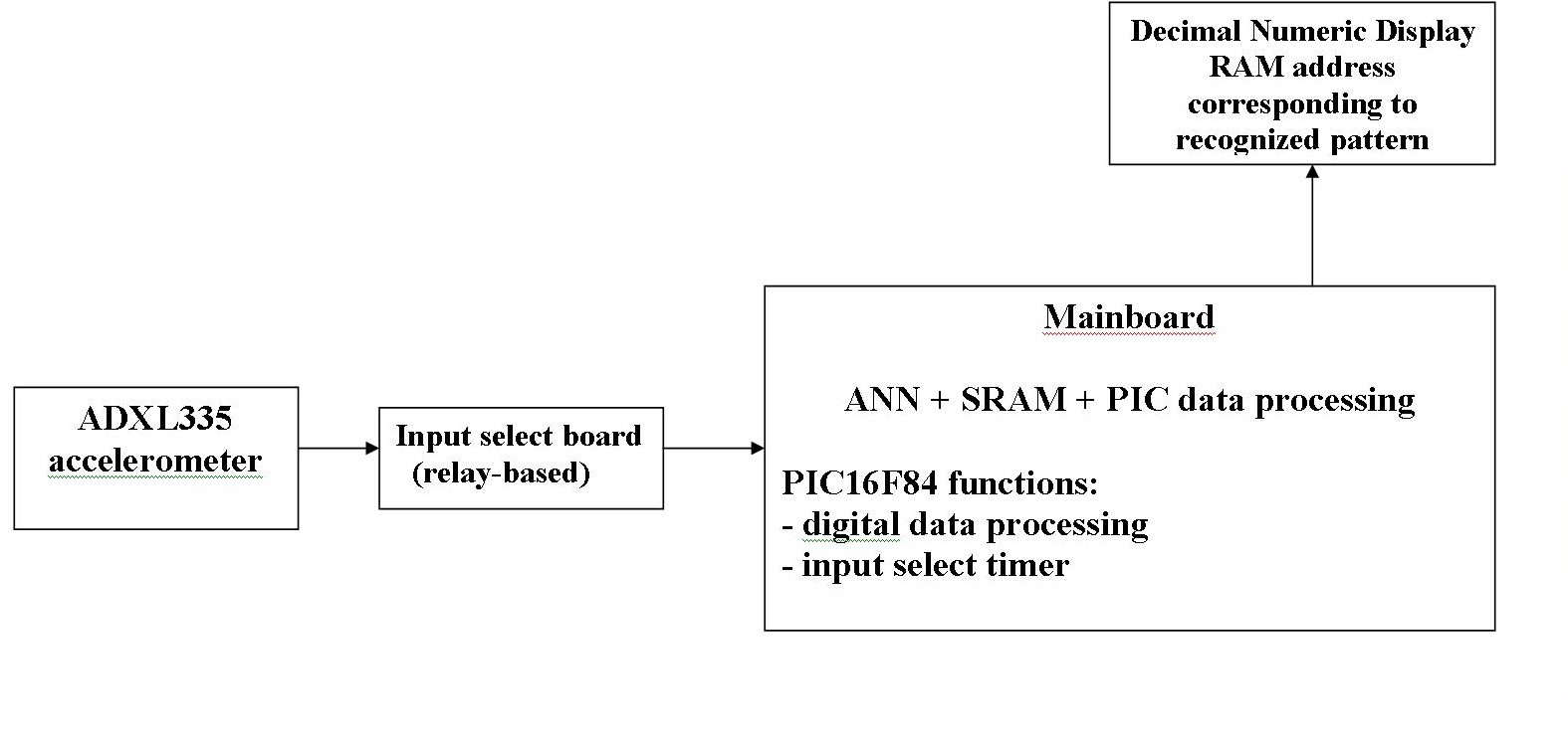
First, the block schematic:
The following modules are present on the block schematic:![]()
- ADXL accelerometer
monitors the vibrations on the wheel shaft and transmits all three connected X, Y and Z axes signals as an output;
- relay board for input selection
According to the HM2007 datasheet and the jumper settings on the mainboard, the "listening" time is 0.9 seconds. Less than that - ANN says "word too short". More than that and ANN outputs the error "word too long". So the ANN input is switched to ADXL output for 0.9 seconds, and for some 0.3 seconds it is switched to GND.
Contains a 12V relay and some signaling LEDs: blue for "Vibra Input" selection and red for "GND" selection.
"STAB" comes from "stabilizer" and it means "power regulator". Turns 12V to 3.3V needed by ADXL335.
Relay handling is done by the PIC16F84 through an ULN2803A open collector circuit.
Connector in left side:
PIN DIRECTION FUNCTION 1 INPUT +5V (extra confirmation) 2 INPUT +12V (ULN+relay+STAB PWR) 3 OUTPUT +3.3V (PWR ADXL335) 4 OUTPUT HM2007 VIBRA IN 5 INPUT ADXL335 SIGNAL OUTPUT (X+Y+Z) 6 GND 7 INPUT PIC RA1 RELAY CMD 8 GND Before any comments such as "why wasting an entire ULN2803 circuit when you could just use a transistor", please understand that I worked using whatever components I can find in the drawers or recover from malfunctioned devices I find in sometimes abandoned warehouses at work.
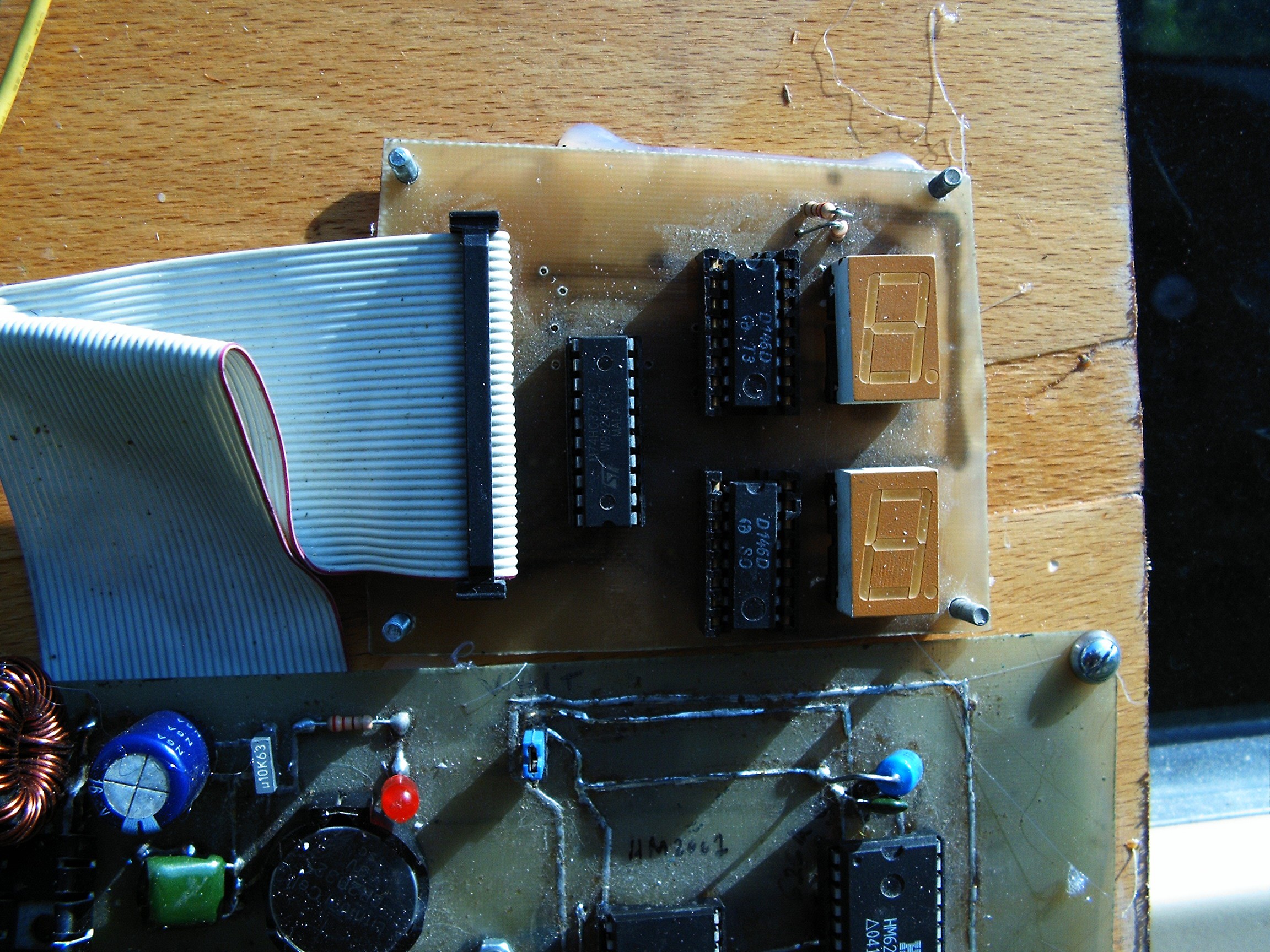
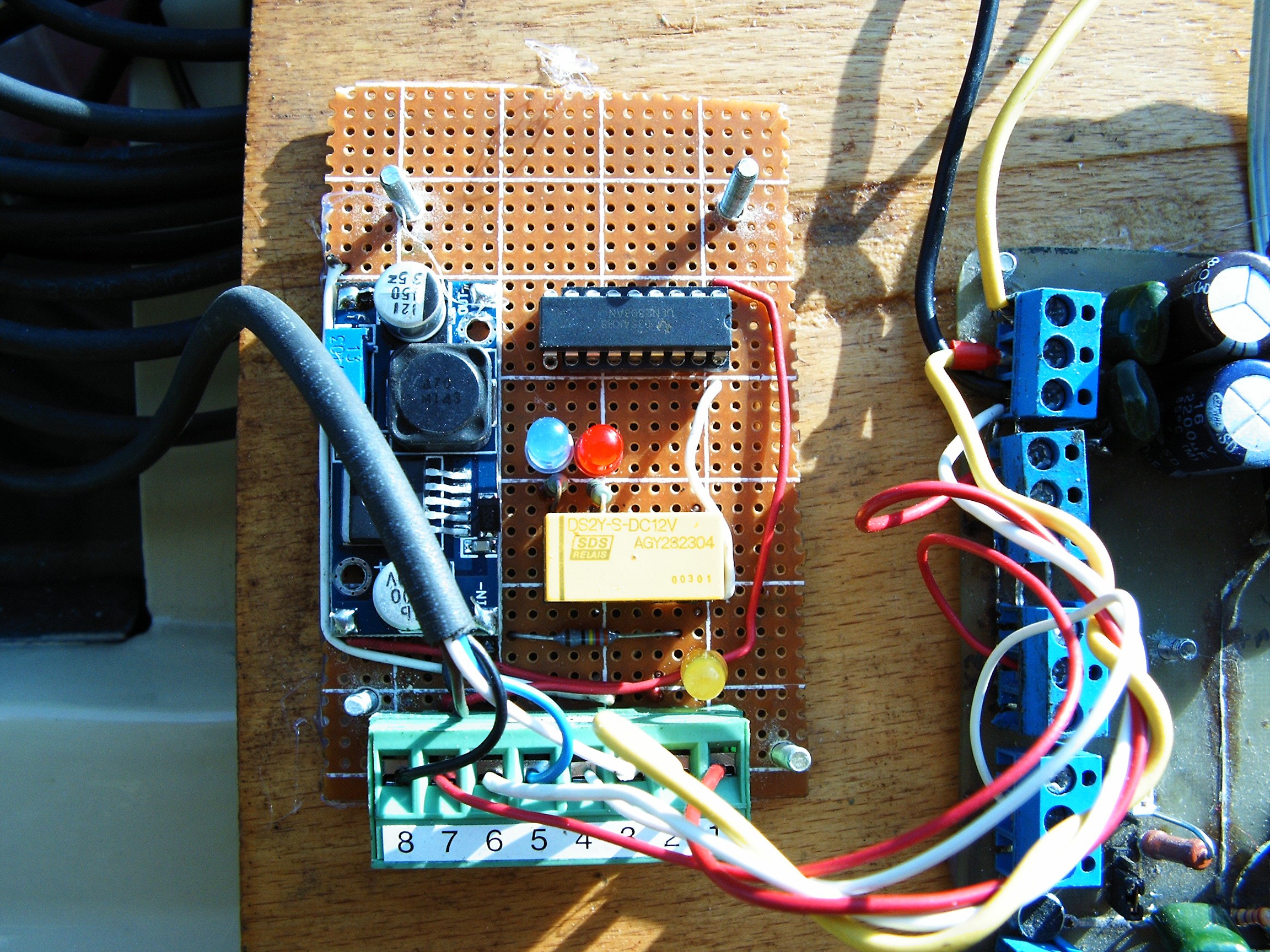
- Decimal Numeric Address Display board
![]()
Displays the error signals or SRAM addresses issued by the HM2007 when certain conditions are met.
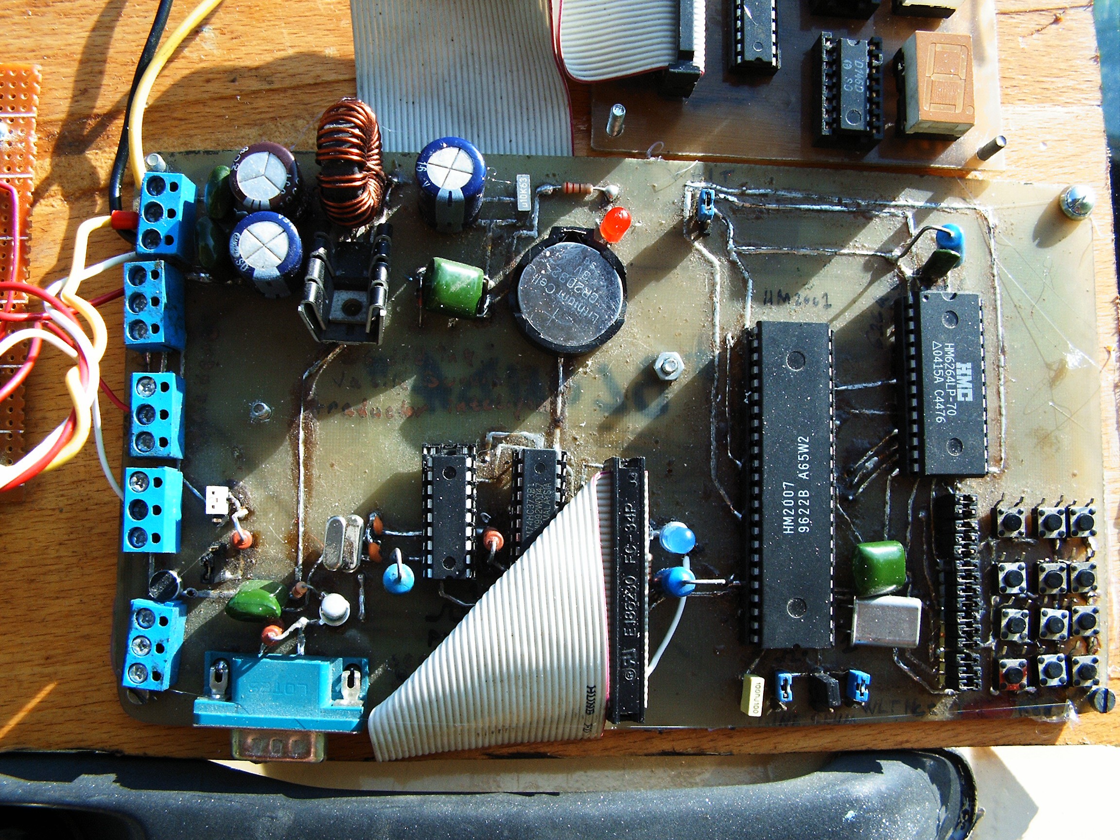
- mainboard
Contains HM2007 (ANN voice/pattern recognition chip), HM6264 (64k SRAM, the Blonde Brain),
![]()
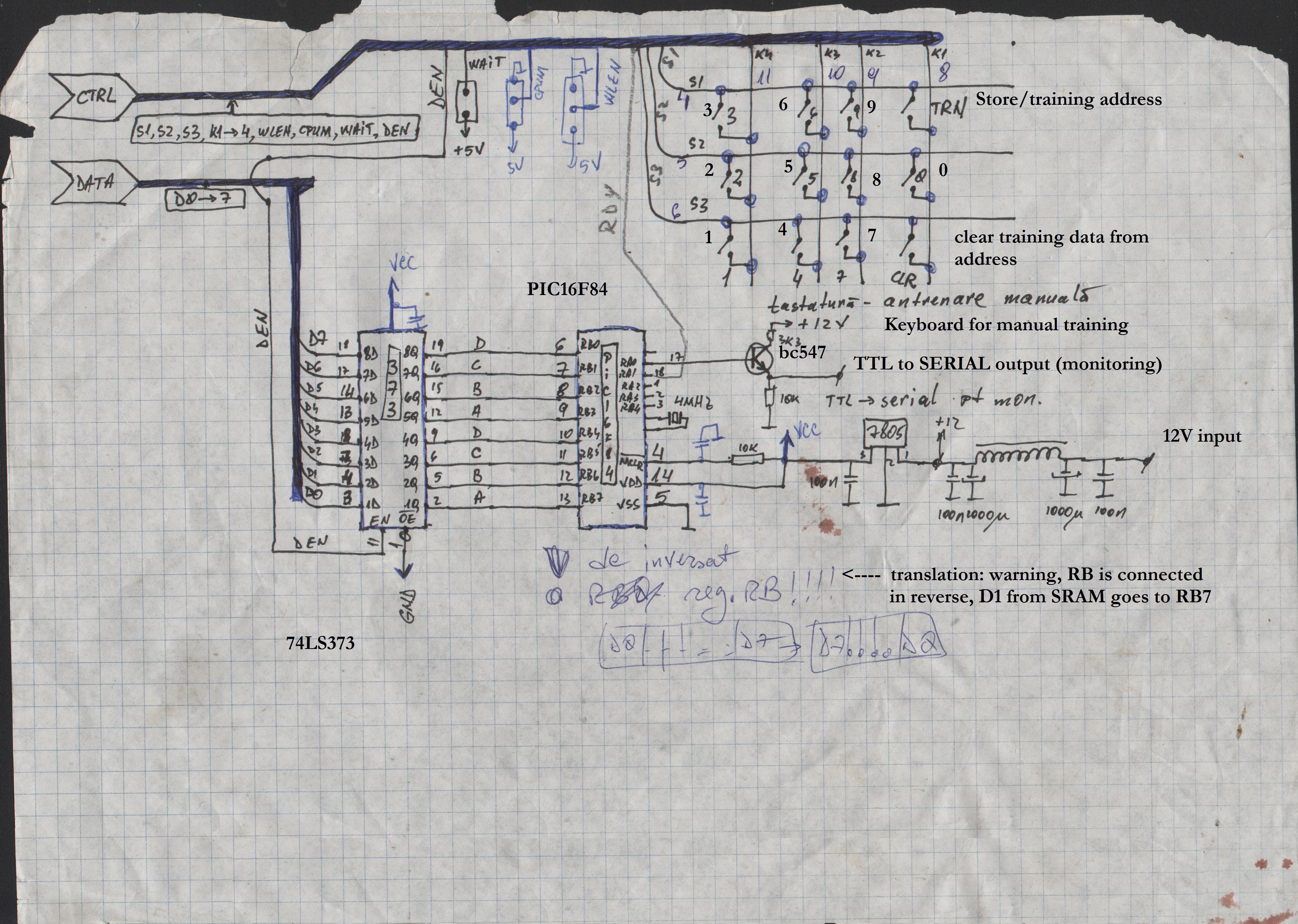
a keypad for user interaction (train data, clear data, address select), a PIC16F84, another power supply and some jumpers.
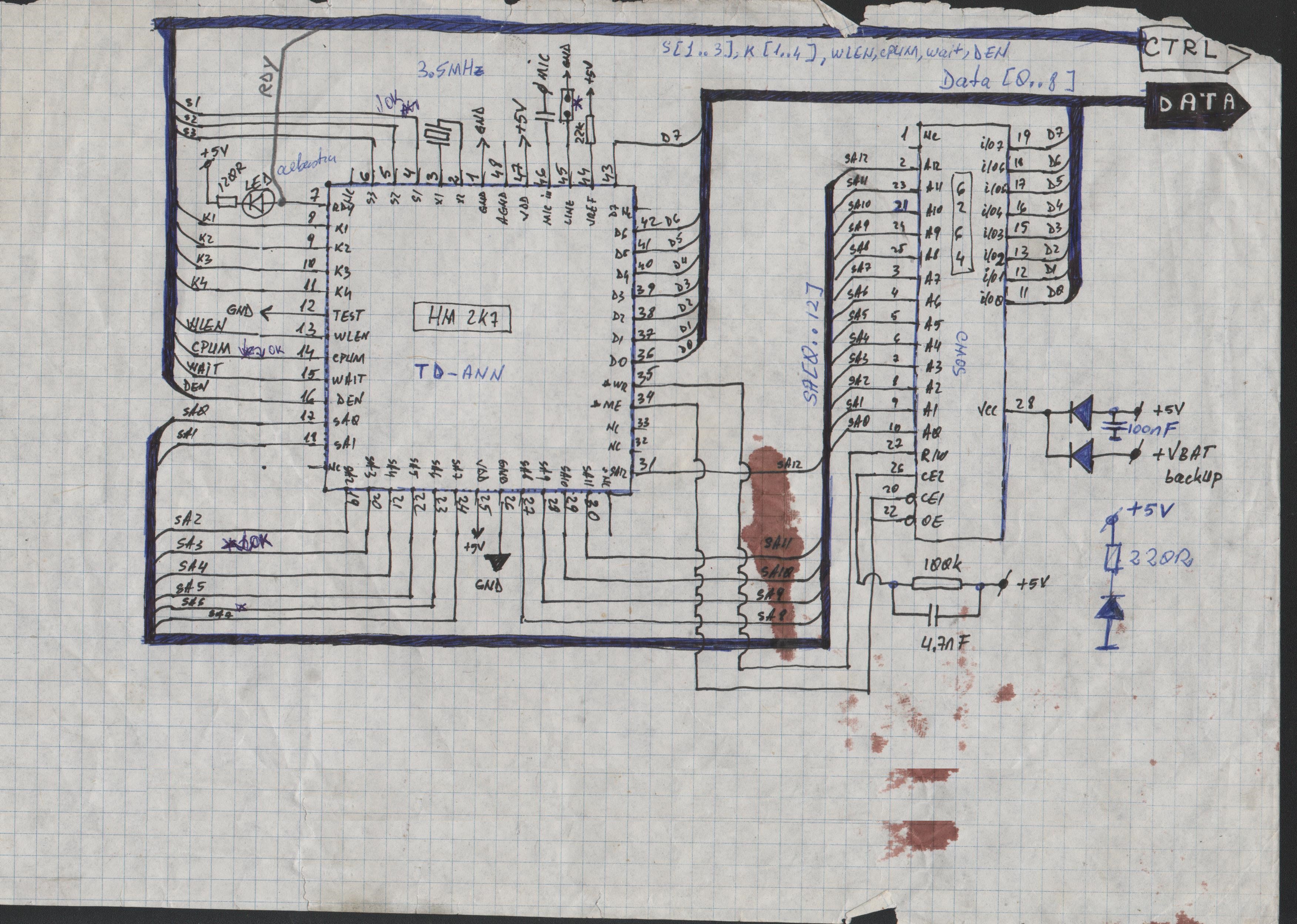
![]()
These pages are scanned from my old magic spell notebook. It was drawn many many years ago, at the dawn of internet era in this part of the world (at the end of the 90s).
So for this project I'm using an old board I designed and made during the old days of CadSoft Eagle 4, when I did not know that program could handle data buses.
Schematics look better on those papers.
So how does it work?
Let's say we are trying to recognize some voice commands. At system startup, there will be two leds active: a red led (pwrOK) and a blue led (READY).
First we need to train the chip so we press the address (for example 01). At this time the RDY line go HIGH (Blue LED off). Pressing "TRN" will turn the RDY line back to LOW (Blue LED on) - ANN is waiting for an input - and we can speak the word. WLEN (word length) jumper is set to 0.9 seconds, so according to the datasheet we've got 40 locations available in the SRAM memory to store the training data [spoken words].
When training the ANN with data (patterns, or words, or voice commands), we need A LOT of training data. Because if we train it saying "three", it will react positive when we say "thirteen" or "thirty". If there's not enough data, it cannot make the differences.
Now - working with repetitive patterns (vibrations) is easier for the ANN. But if we are not careful, we get the "word too long" error, so this means we have to periodically separate the ANN input line from the vibration source. This is where the relay input select board is coming.
Alright. Now what's up with that PIC16F84?
Well, it performs two functions:
- 1. getting the address bus numbers and do something with them - not implemented yet;
- 2. When RDY signal gets low (this usually means keypad interaction), the 0.9s/0.3s input selection is suspended. When RDY signal goes back high, relay waits for another 0.5 seconds before switching back to VibraIn input. I need this extra time interval for in-house testing. I'm using a drilling machine with different RPMs in order to check if this is working.
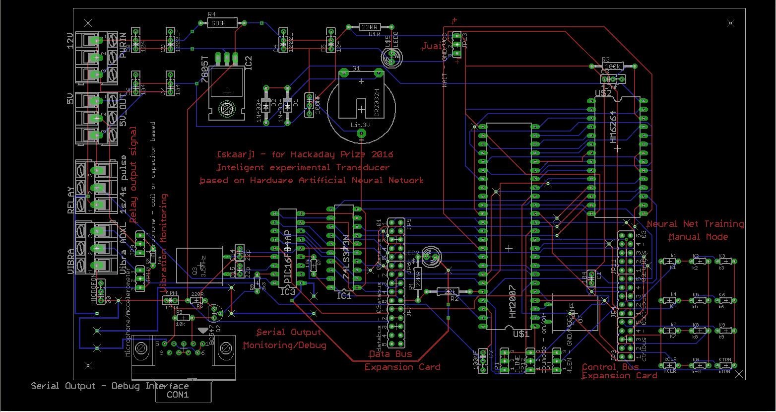
Mainboard PCB
This is my first schematic I ever made in EAGLE. It was version 4, libraries were incomplete and I had to replace keypads and microphone with whatever components (libraries) I could find.
![]()
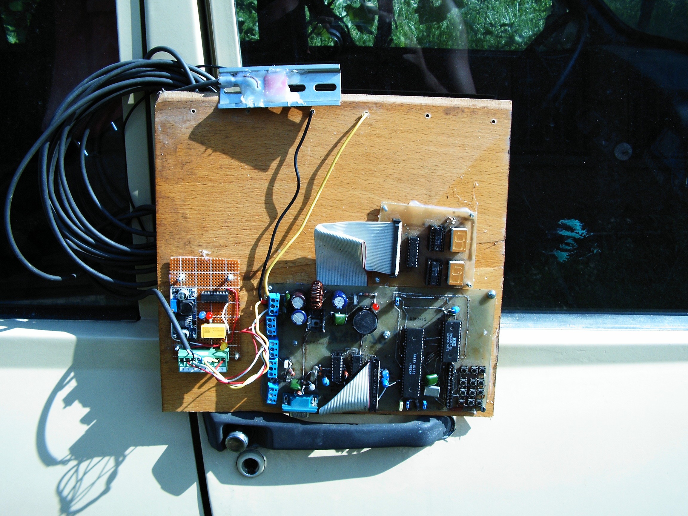
And this is the final system:
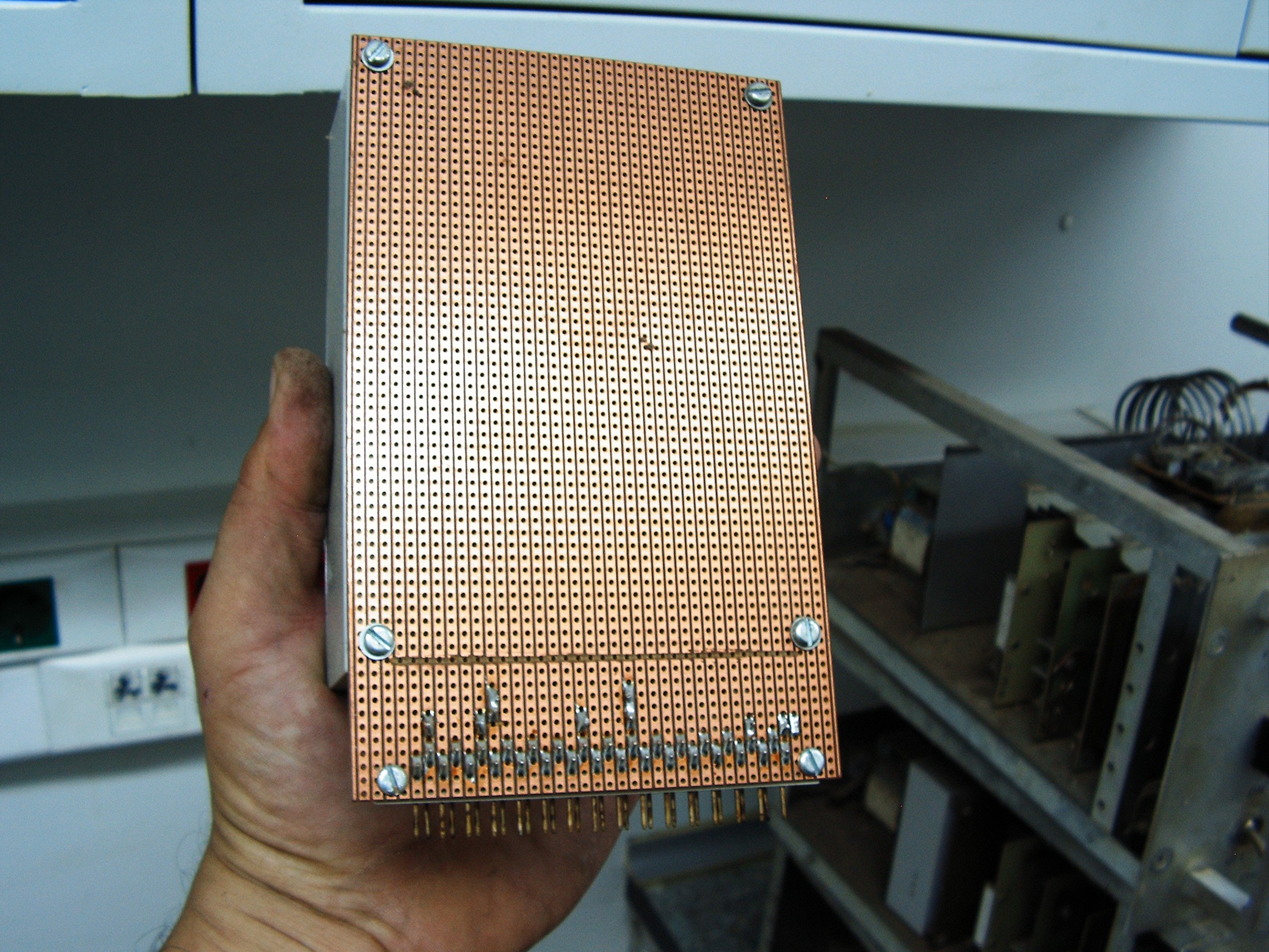
Some people used to 3d printing, fancy tools, CNCs or fancy methods with laser printers will find that board an abomination. Yes, it is horrible. t was built using whatever materials I could find, it was painted with marker and corroded in FeCL3.![]()
Holes were done by hand by overlapping a printer paper over the PCB. At printing time, paper schematic was a little smaller than the reality so imagine the chaos when I had to insert the HM2007 socket. Marker was expired so FeCL3 corroded through it and damaged most of the PCB wiring. This board is double-sided, entirely made by hand. Those were the conditions at that time. And most important - I built it to last, it is UGLY, DIRTY, full of dust and amazing - it still works after so many years.![]()
On top there's the ADXL335 accelerometer, installed on a metal base used for automatic fuses:
![]()
ADXL pressed and fixed with melted plastic
![]()
let it cool down
and it's ready.![]()
![]()
![]() Connected here: pin3 = 3.3V, pin5 = VibraIn, pin8 = GND.
Connected here: pin3 = 3.3V, pin5 = VibraIn, pin8 = GND.
ADXL will be connected on the rear-right axle.![]()
At this time I am forbidden to do this operation. It's too extremely hot today and she does not want me to risk my health and leave the house. I have to stay inside, locked in jail all day long. Maybe tomorrow when storms will start again AND I WILL FIND CHICKEN IN THE CAR - AGAIN!!!!! They come through the hole under the pedals to hide inside over night.
I won't install the sensor until I see the spectrograms flowing on screen displaying the vibration data, just like in the old times.
In the mean time - first experiments:
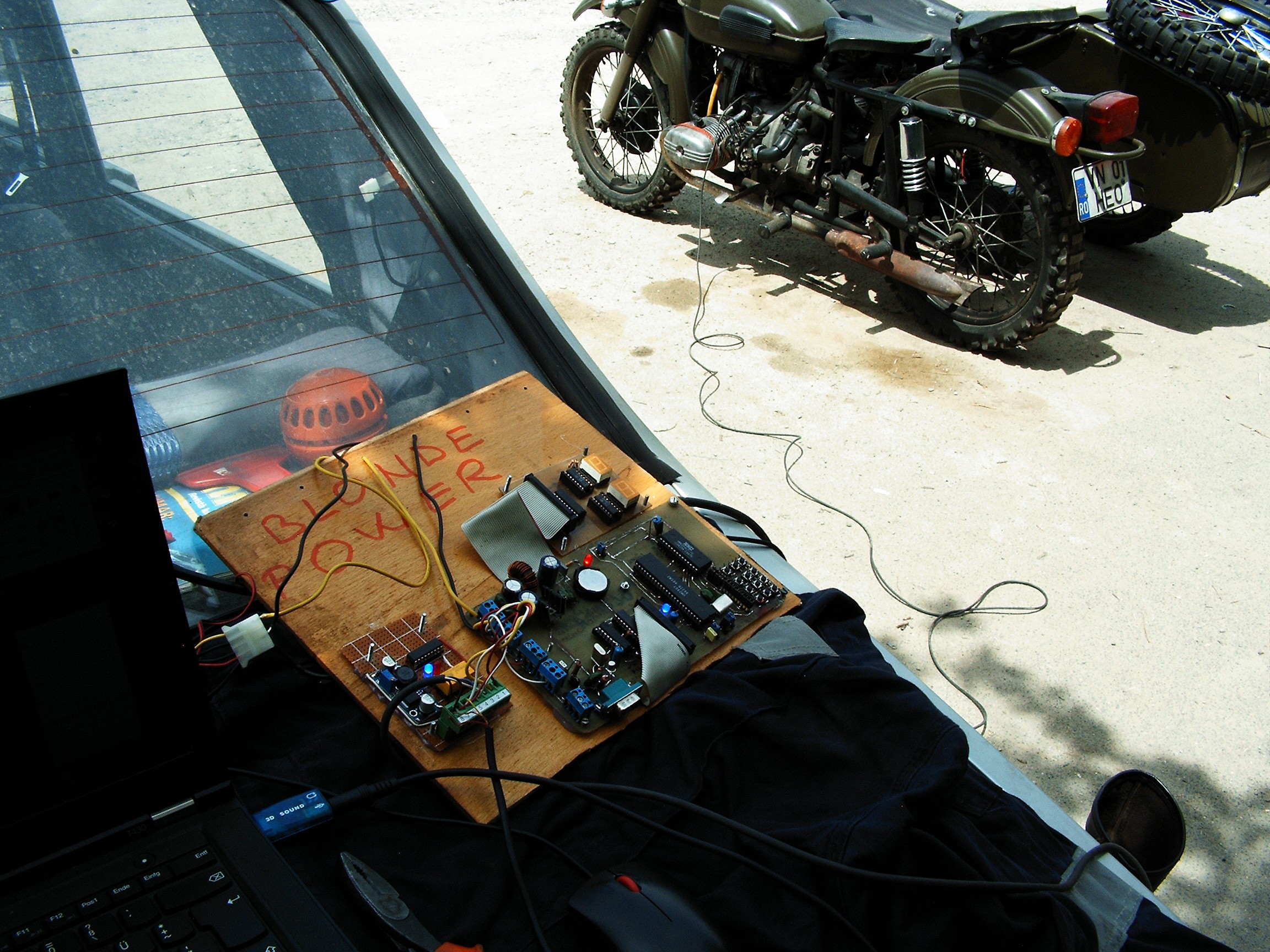
![]()
ADXL installed between alternator and engine block. Cable goes to "Blonde-Powered" ANN as described above. In parallel, the signal line goes to an USB sound card, microphone input.
![]()
![]()
Laptop running Unix FreeBSD 11.0-ALPHA5, with Baudline for monitoring and Gimp Toolkit for screenshots.
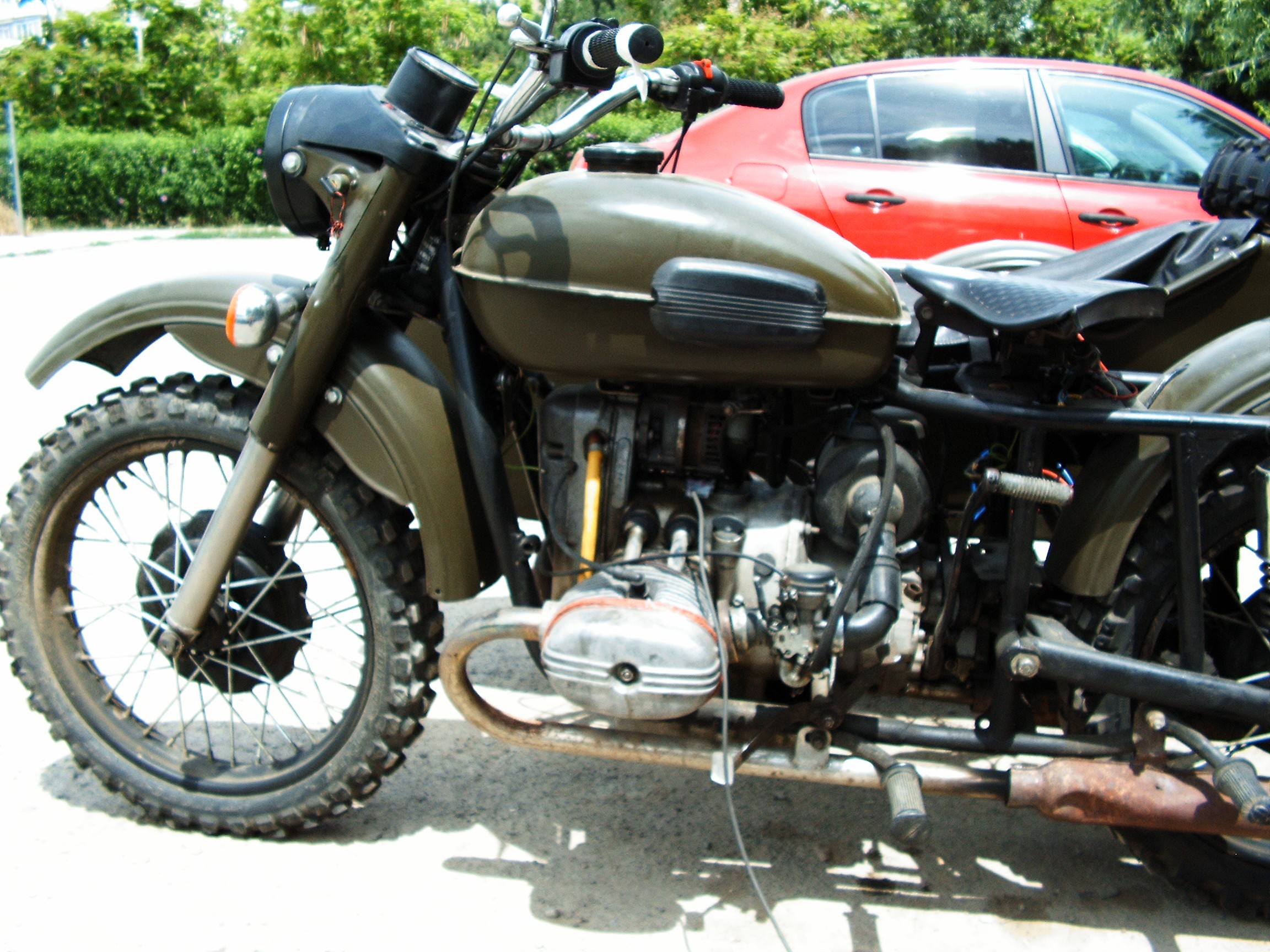
![]()
This is the system, and here is the audio data I gathered from the accelerometer while running the motorcycle engine.
In the mean time, in-house testing:
![]() Accelerometer knocked with a knife:
Accelerometer knocked with a knife:![]()
Accelerometer scratched with a knife:
![]()
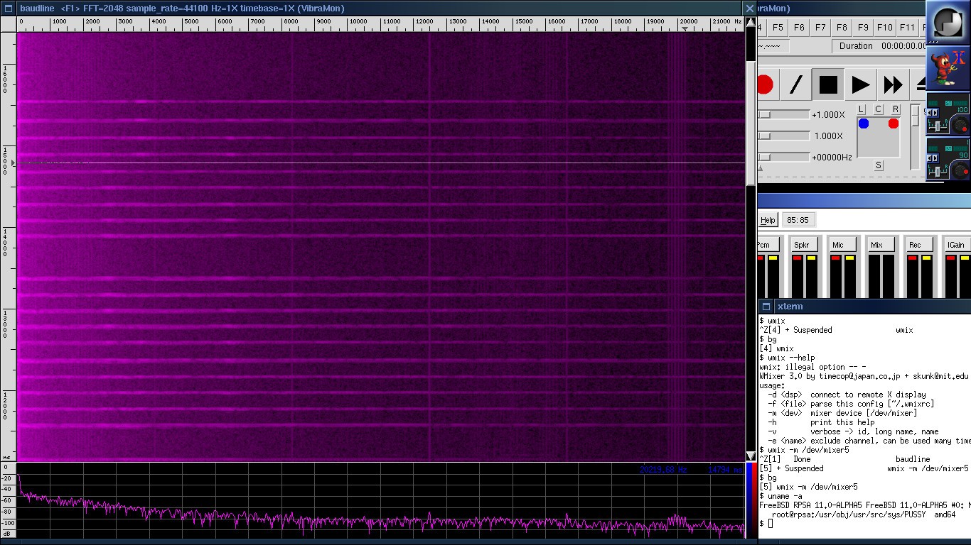
Spectrogram - ADXL accelerometer sitting on the left cylinder head where vibrations are the most horrible.
Also there's some constant noise in the upper spectrum. I hope it's the USB card reaction to the WiFi signals in that area.
You may notice that the mp3 contains distorted sound. While sitting on the rear axle, the vibrations won't be so terrible as this case. We'll see. That's why I need measuring devices, especially this wonderful tool called 'baudline'.
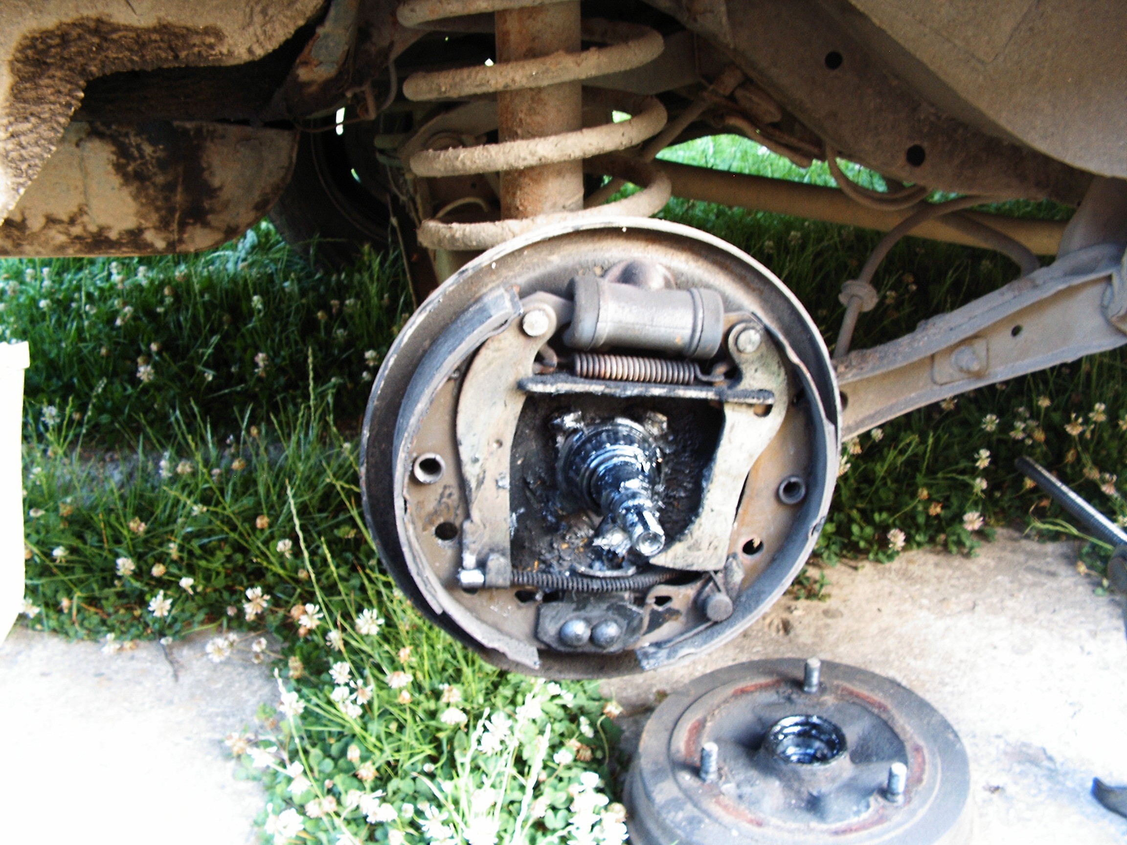
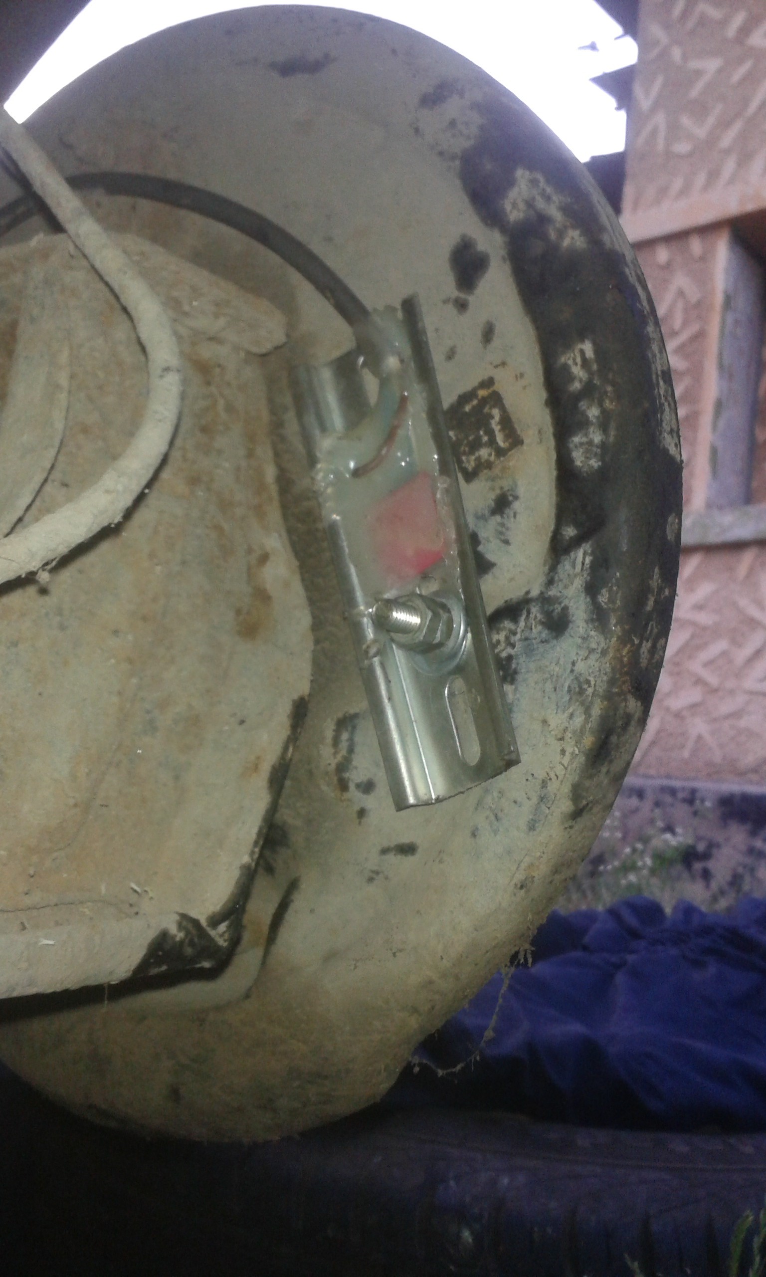
Accelerometer was installed behind the rear-left wheel mechanics.
![]()
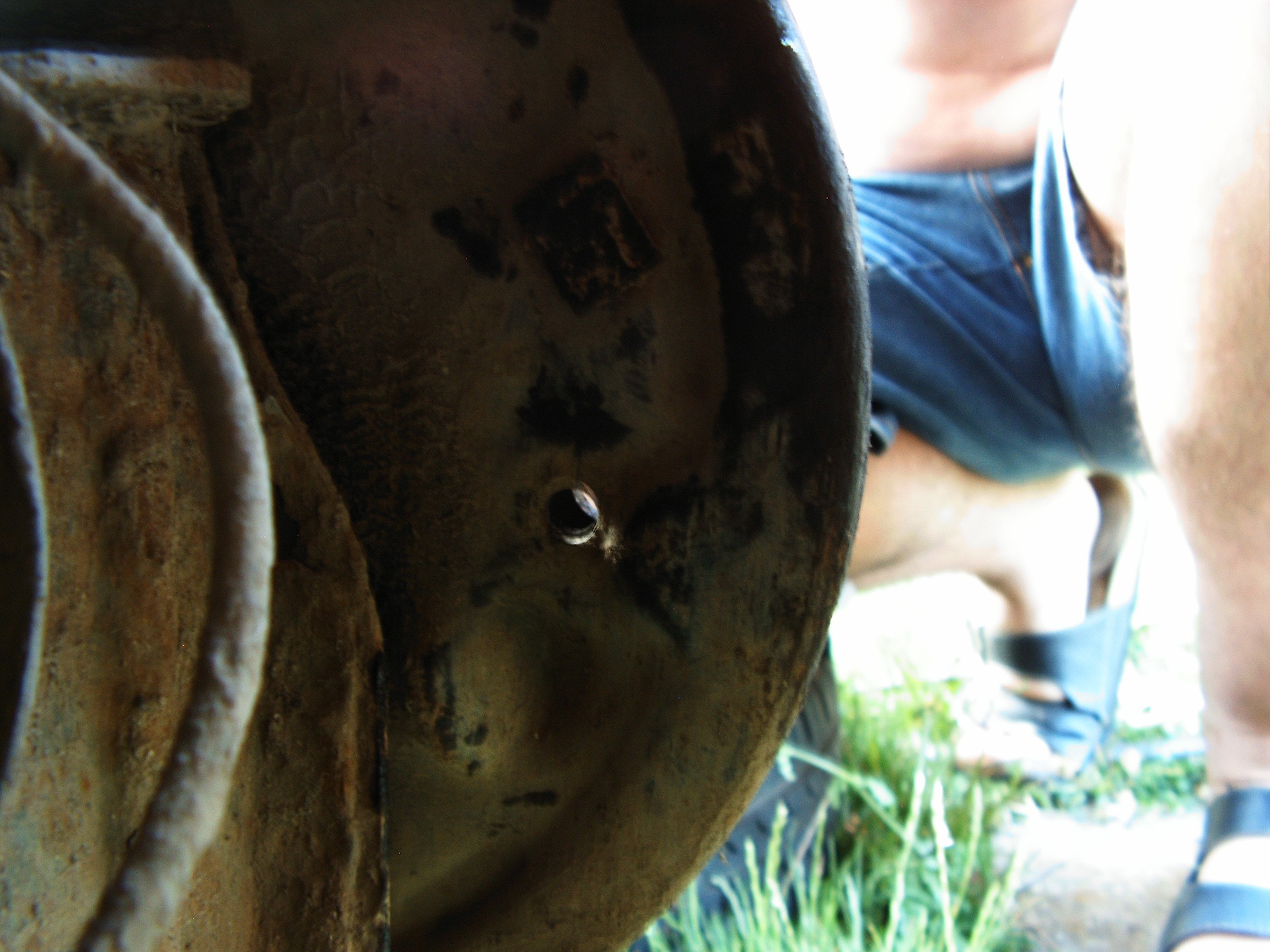
First - cover removed.
Behind the left-side brake plate there are some holes....
![]() That's it. Here we go.
That's it. Here we go.![]()
Perfect.![]()
Storm is coming, need to move fast. Everything fixed in position.
Modern cars are tested for bad inside sealing using modern tech, such as controlled air/water jets, fumes and sensors. If something leaks inside the car, the project is remade.
However, Dacia tests were performed much simpler by using cats. Engineers locked a cat inside the car and left it in the sun. Wherever they could see the cat's head coming out, they marked the place and covered the hole with fiber glass.
In my case there are still a lot of holes left so it's easy to bring the sensor cable inside.
Now - tests.
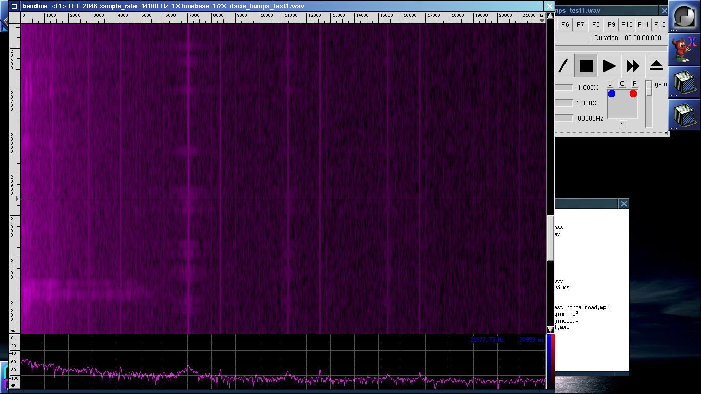
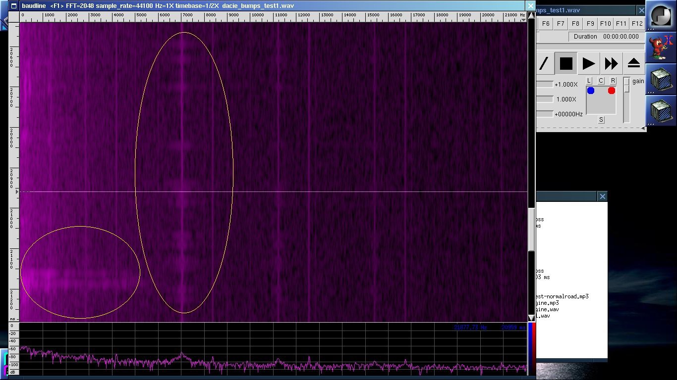
First - driving on a bad road with a lot of bumps. File is in MP3 format, if you plan to use baudline, you must also install mpg123.
Here's a screenshot:
To see the bumps, they need highlight, so same picture again:![]()
There's a lot of noise due to the high voltage in the spark plugs. Not sure yet how to get rid of that.![]()
Another recording - normal road driving. At high volume at the end of recording you will be able to hear the brake scratching.
[END OF TRANSMISSION]
______________________________________
kernel panic: improbability coefficient below zero
-
Science Time (IV): Dacia 1310 Engine Exhaust Gas Analysis using TCD Gas Chromatography
06/20/2016 at 16:23 • 4 commentsGood Morning and welcome to the 4th edition of [skaarj]'s Science Time log.
Today we are going to review the analysis results using the rebuilt/repaired gas chromatographs described in the previous log. The experimental setup is described, and a set of results is discussed.
From the beginning we have to set the things clear. At first I almost started to believe that my planned Citizen Scientist approach for this project failed for good. Somehow the Divine laughed at me and said something like "Let there [skaarj] hack his way out of this" and I was given the Chromatograph, and the rest of the story is known. The device is "calibrated" using expired gas calibration tanks, it was rebuilt in a hurry using questionable methods such as FID to TCD conversion plus electronic parts and wires found in the drawers. Rats and humidity tampered with most of the wiring and - most important - there is A LOT OF NOISE in the output signals and the precision of this monster is unknown.
1. Experimental Setup
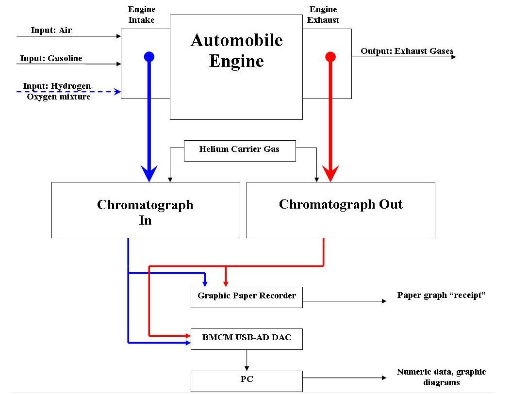
For the beginning, this is the block schematic of the proposed Exhaust Gas Analysis system.
![]()
This is my proposed block schematic for presenting a generic gasoline ignition engine and my way of tampering with it. Carburetor stays on top of the intake manifold and performs the air-gasoline mixture. Additionally there is a hydrogen-oxygen gas source which is mixed with the air.
Input mixture goes into the engine, but there's a small hose (blue color in the figure) going to the first Chromatograph unit (Chroma In).
A small part of the exhaust gases is extracted through a second hose (red color in the figure) going to the second Chromatograph unit (Chroma Out).
Both of them perform the gas analysis as described at the beginning of the previous log.
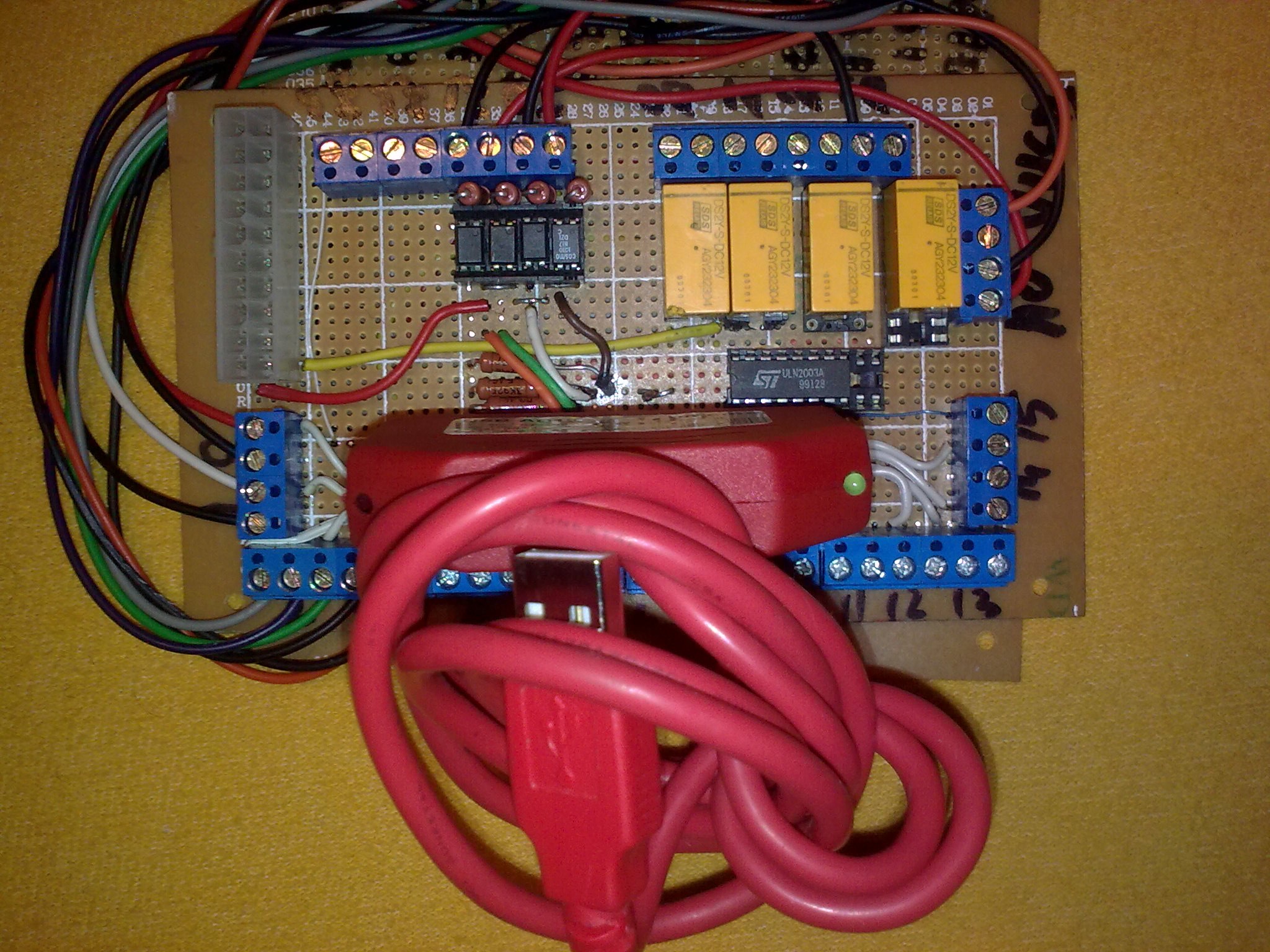
Output signals from both Chromatographs are connected to both the paper graphic recorder and a data acquisition card connected my old laptop to dump all the numbers.
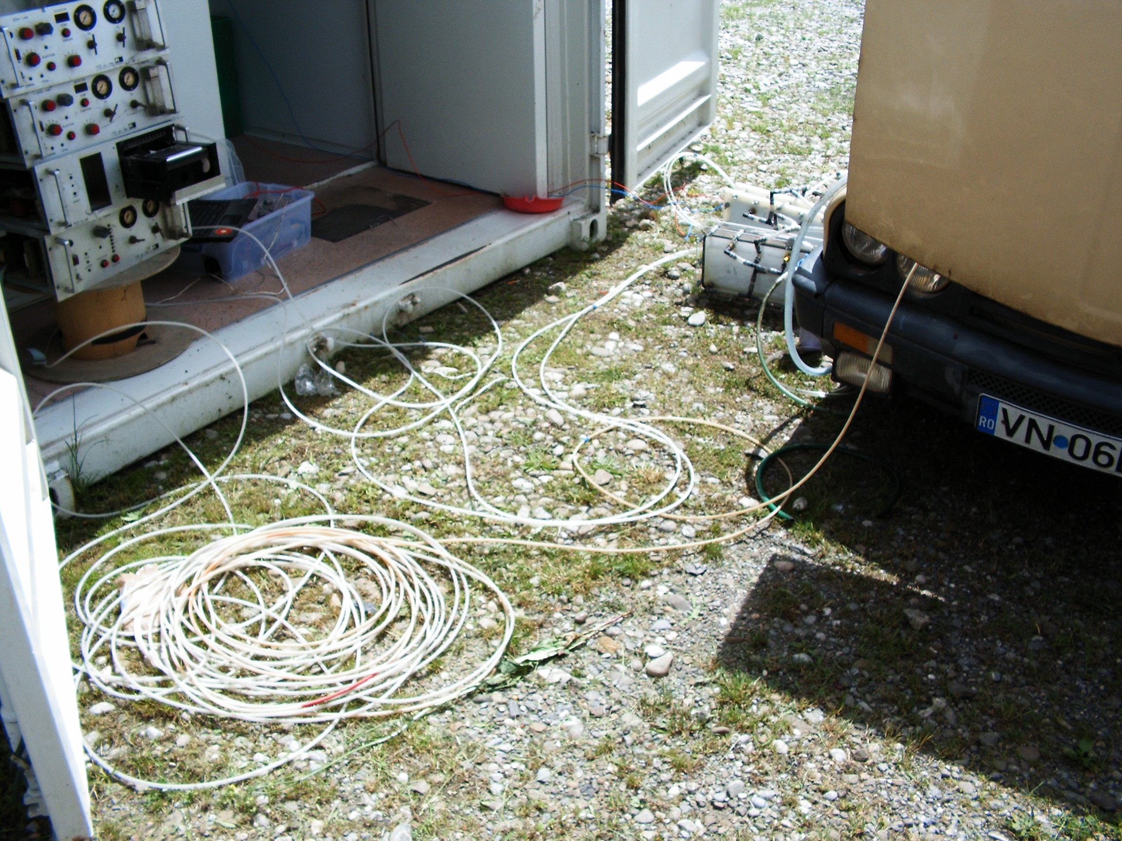
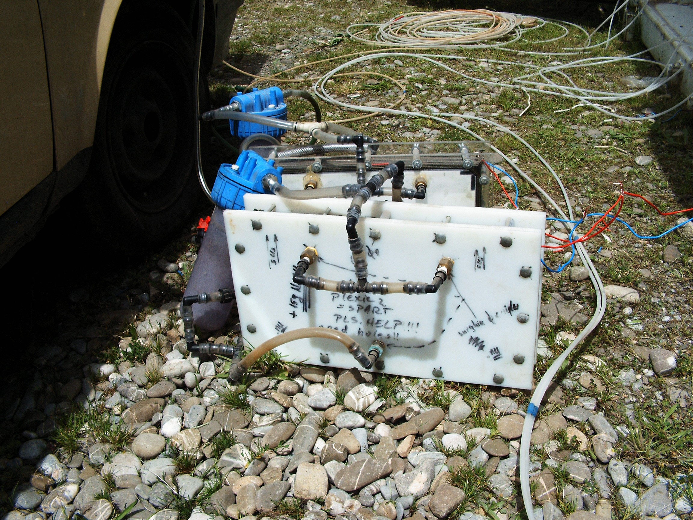
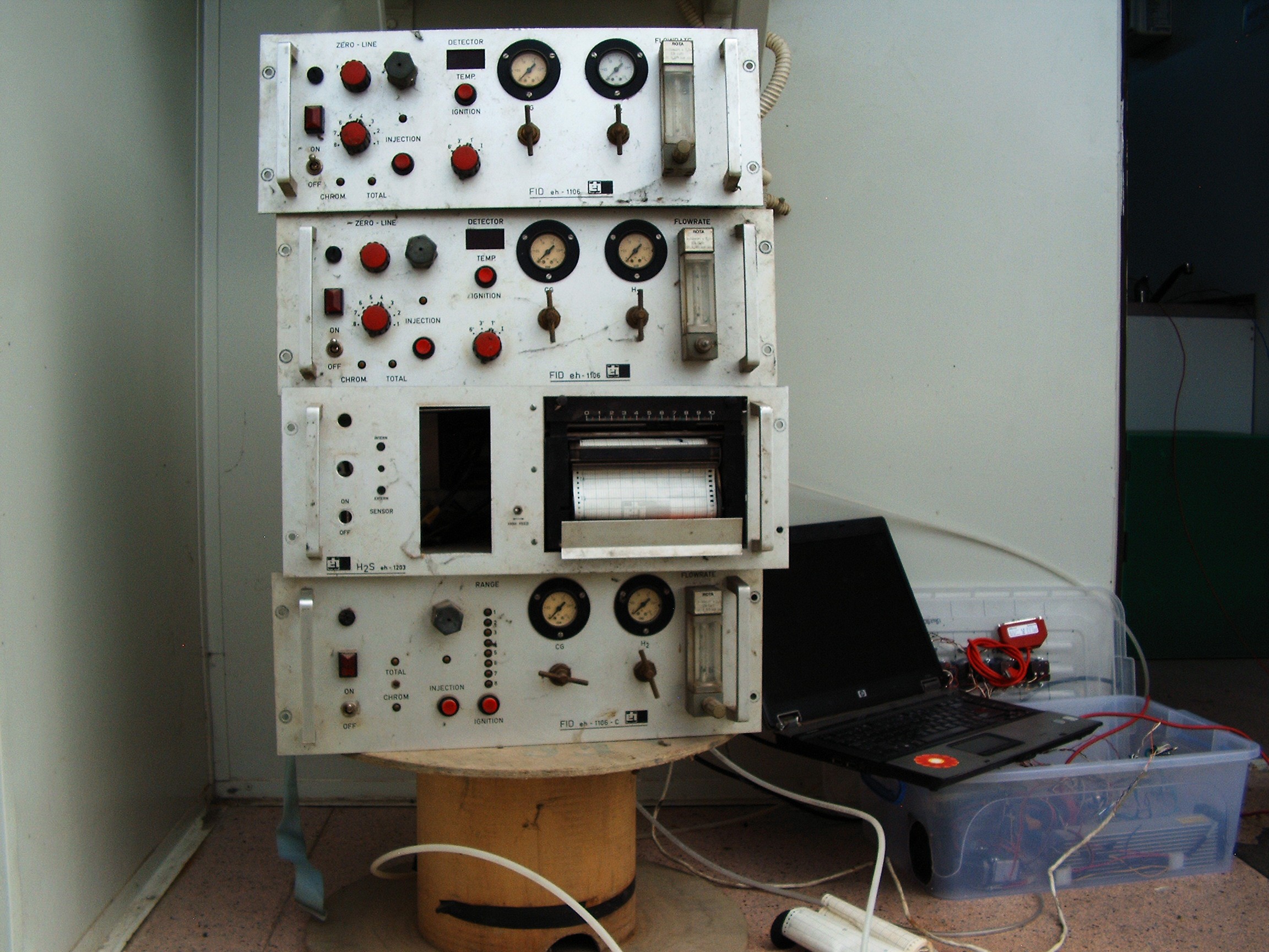
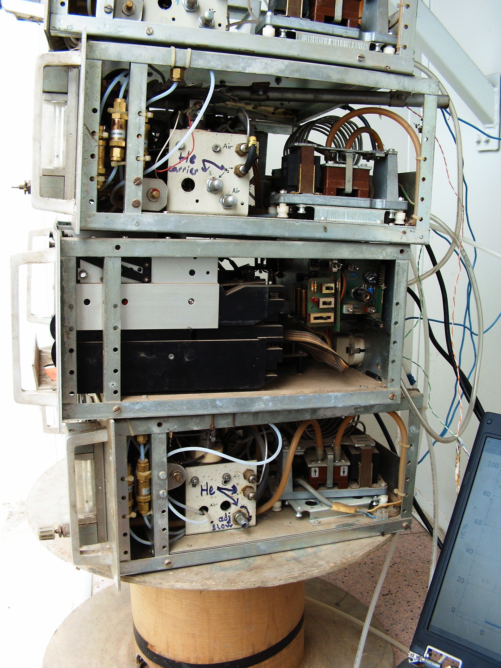
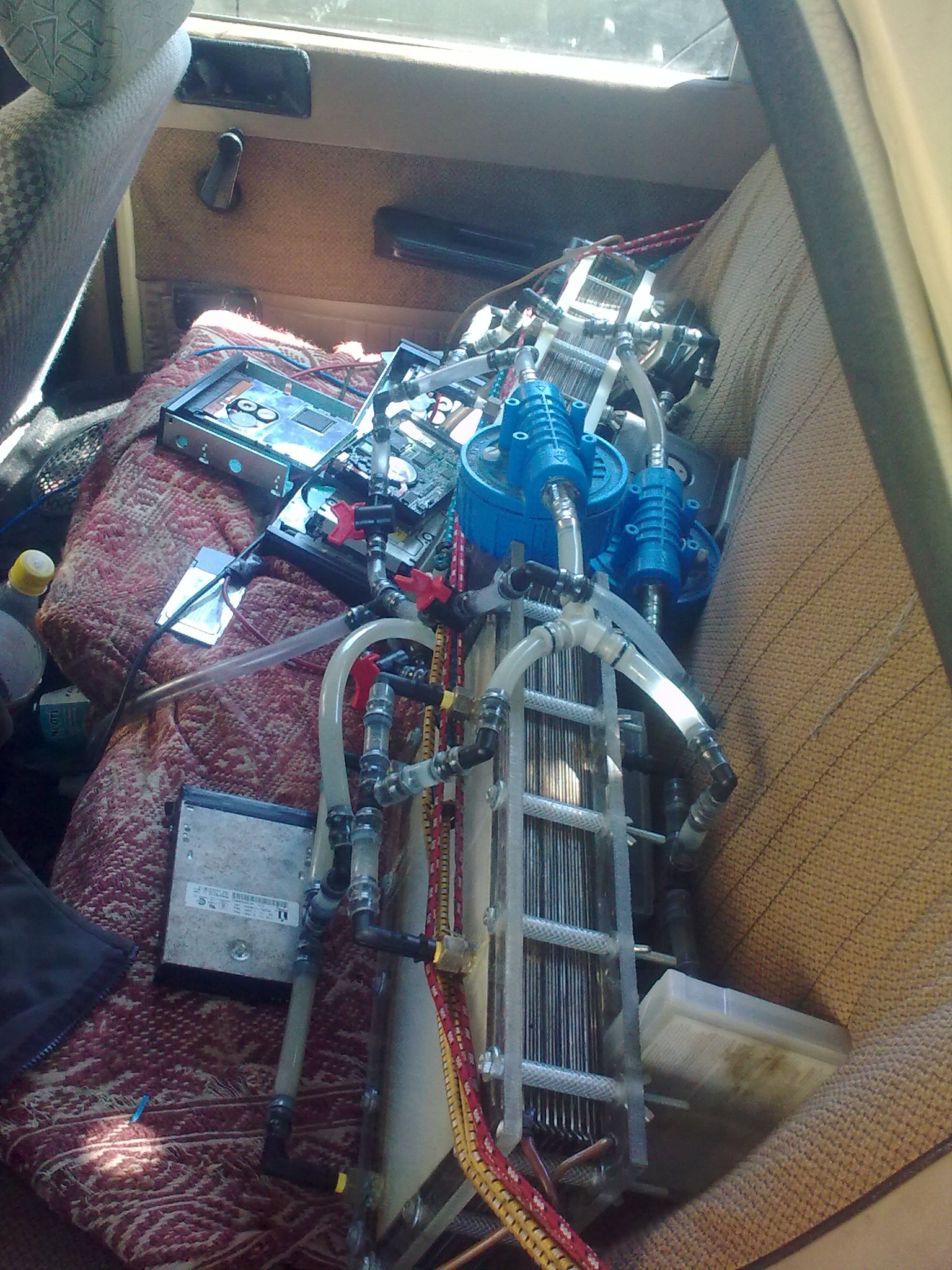
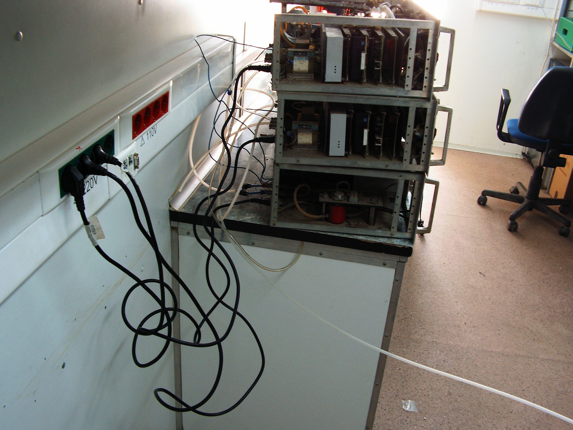
![]()
From left to right, top to bottom:
1. Chroma In, Chroma Out, Paper Graphic Recorder (no paper), Spare Chroma;
2. Hose in the left: air intake line; hose in the right going to the back of the car: exhaust line;
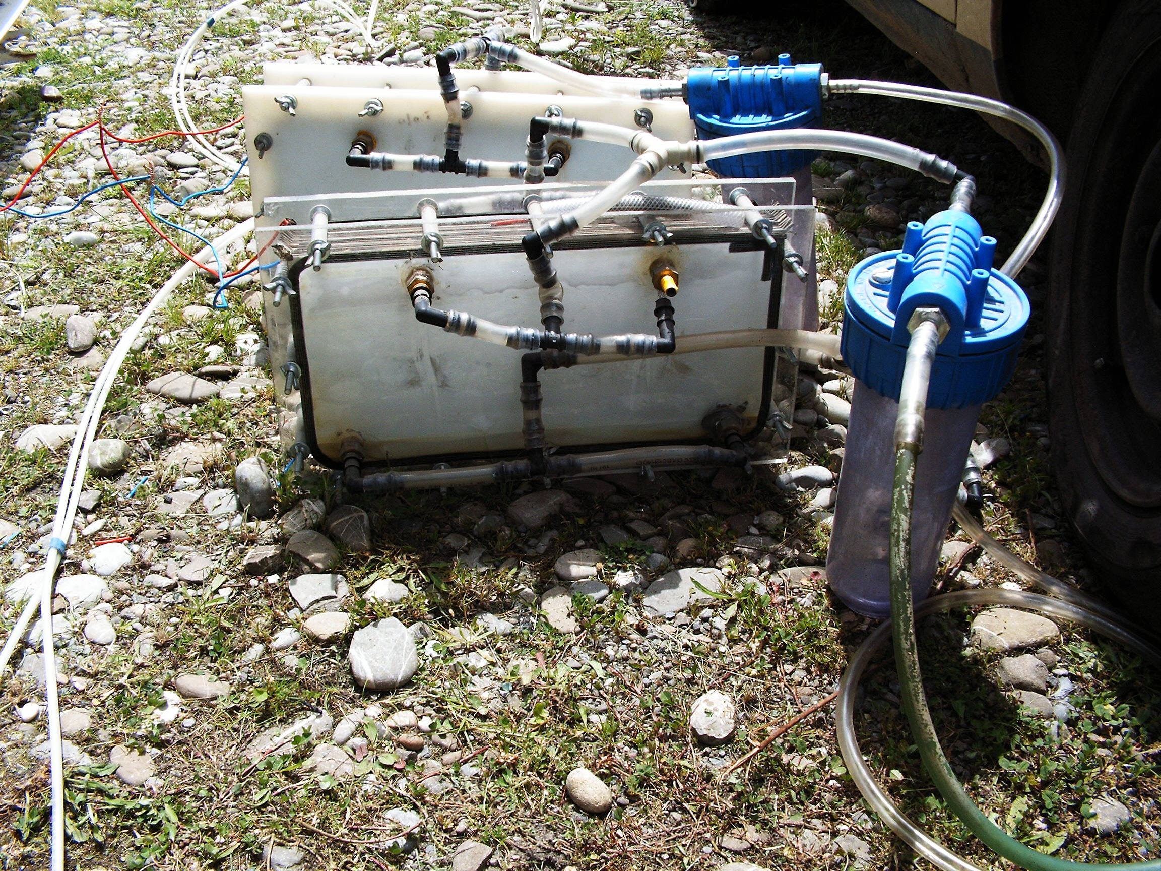
3. Those two strange things near the right side container door: hydrogen electrolysis reactors;
4. Dacia 1310MLS, made in 1986, engine capacity 1297cc, maximum speed (when wind blows in the rear) 100km/h; time to reach from 0km/h to 100km/h: around 10 minutes; engine pollution factor: SKY HIGH.
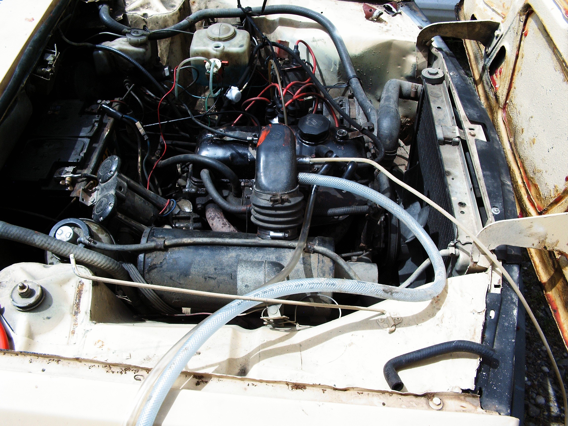
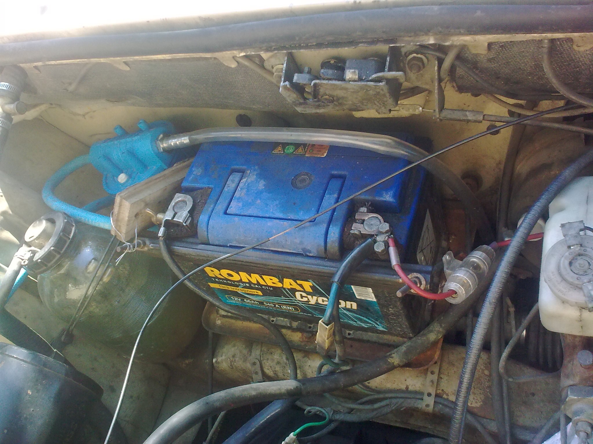
![]()
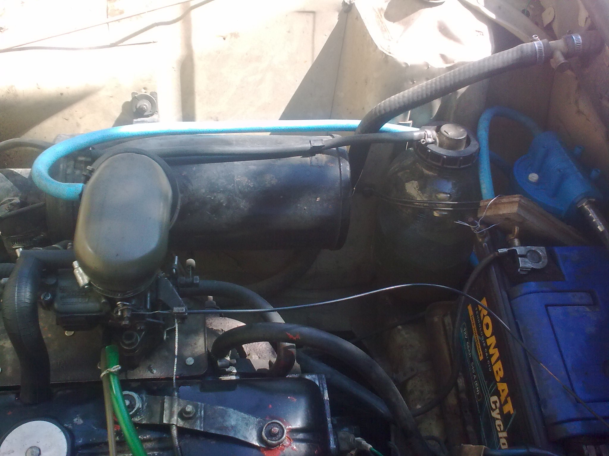
Dacia 1310 engine. Still looks nice and still doing its job after so many servicing years.
Big hose - hydrogen from first electrolysis reactor connected to air intake hose (black thing curved like a glove);
Big transparent hose - hydrogen from second electrolysis reactor, connected directly to engine air intake manifold under the carburetor;
The big black round cylinder (bottom side) is the air filter. In its left side there is a glass receipt containing the coolant (distilled water). Air intake hose sits on this cylinder, and the other end covers the carburetor air intake.
That red paint on top of the air intake hose is liquid silicone covering a big hole.
Small white hose near the hydrogen hose: Chroma In Gas Line.
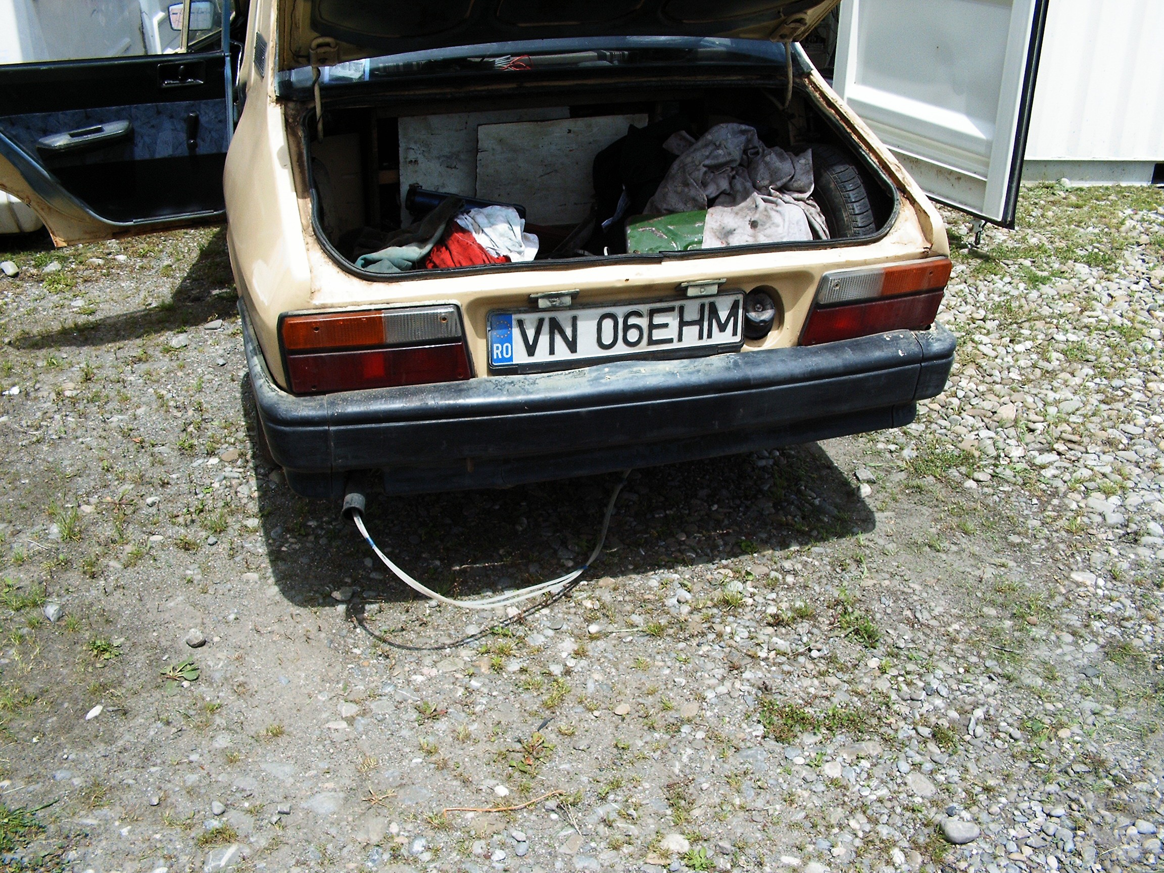
![]()
Two hoses inserted in the exhaust pipe. Those are going to Chroma Out.
![]()
Welcome back to the Madhouse. This time we get to visit the yard.
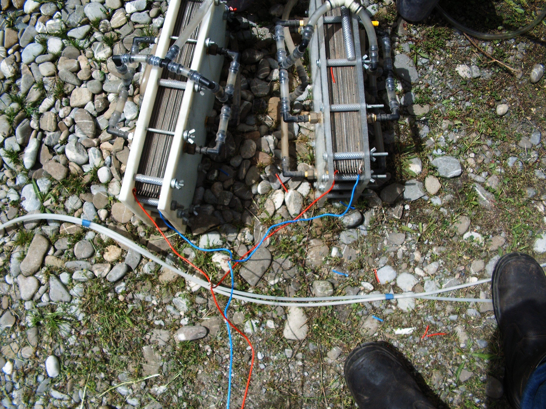
Hydrogen Electrolysis Reactors
![]()
Construction and functionality of these electrolysis reactors is described in Science Time (II) log.
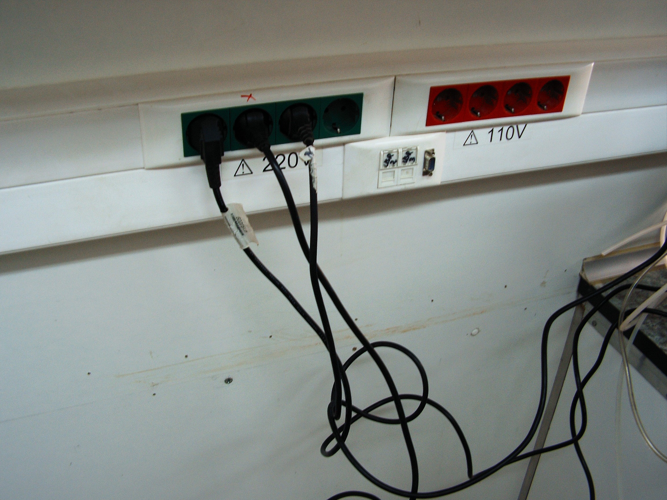
They are electrically connected in parallel and powered at 220 volts direct current. Not AC, but DC, rectified through some HUUUUGE diodes used for welding. I also have 110V in the cabin but it's not so funny to use.![]()
Both electrolysis reactors are filled with distilled water and 1.5% NaOH. Unfortunately, Potassium Hydro Oxide (KOH) has a better efficiency in producing hydrogen through electrolysis but this product is strongly regulated in the European Union due to its... dangerous properties. This time there's no more police supervision so I must be careful and do all the things right.![]()
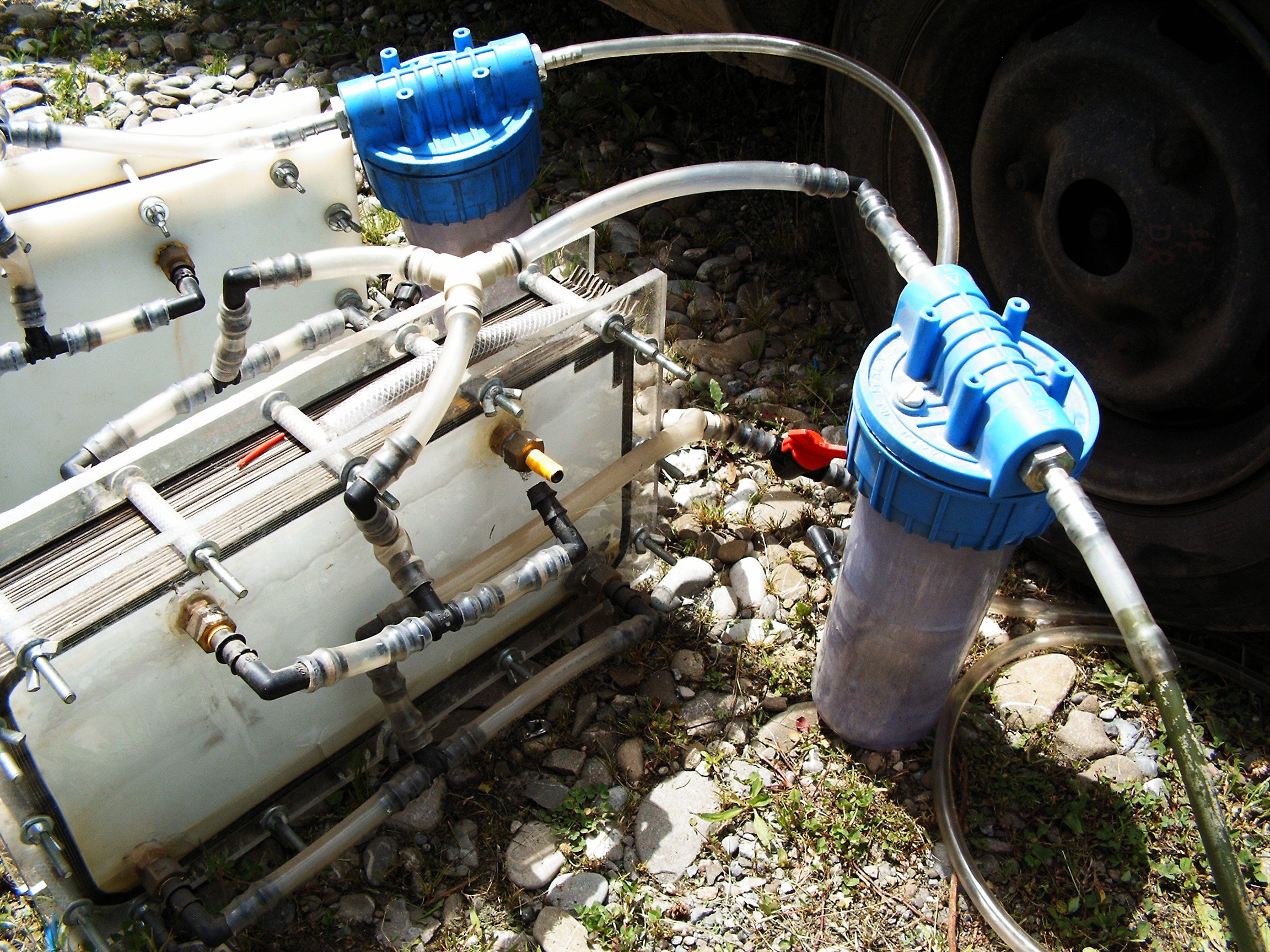
As described in the Science Time (II) update log, each reactor output is protected with a bubbler filled with distilled water. Unfortunately I do not have any spark arrester, so in case of a reverse spark - the flame will stop inside the bubbler at water surface. This is a safety measure. If those bubblers are not present and there's a reverse spark happening, those reactors can EXPLODE.
![]()
Pulsing the reactor with variable voltages - as some myths on the Internet suggests - did not show any increase in hydrogen flow. So 220 volts rectified.
As you may notice, on the transparent reactor there's a disconnected hose. There is also one disconnected on the other reactor. That's because I want the hydrogen to go streight out in the open while the powered reactors reach the proper temperature - I don't want more than 60 degree Celsius, or else steam (from distilled water) will start to come out.
Second reactor.![]()
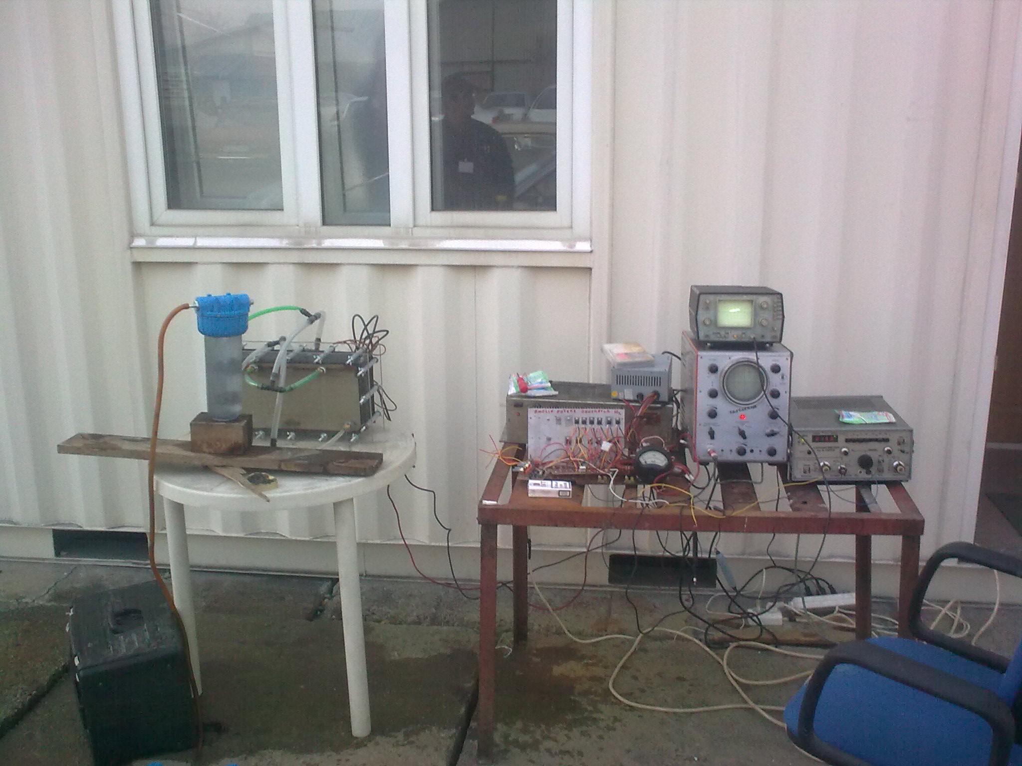
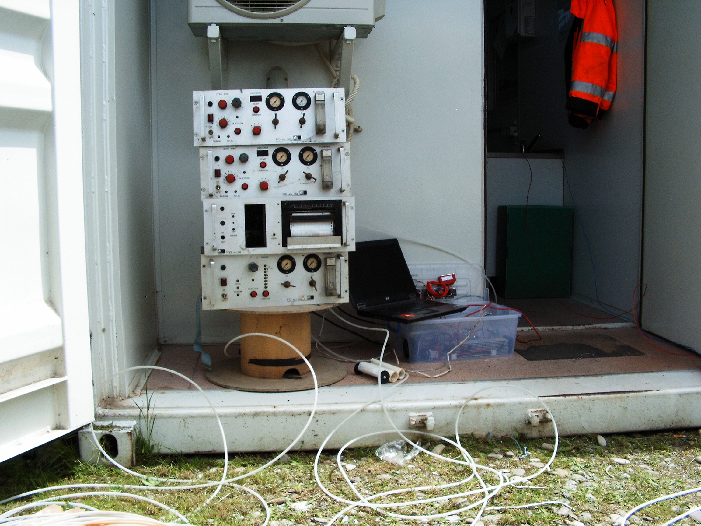
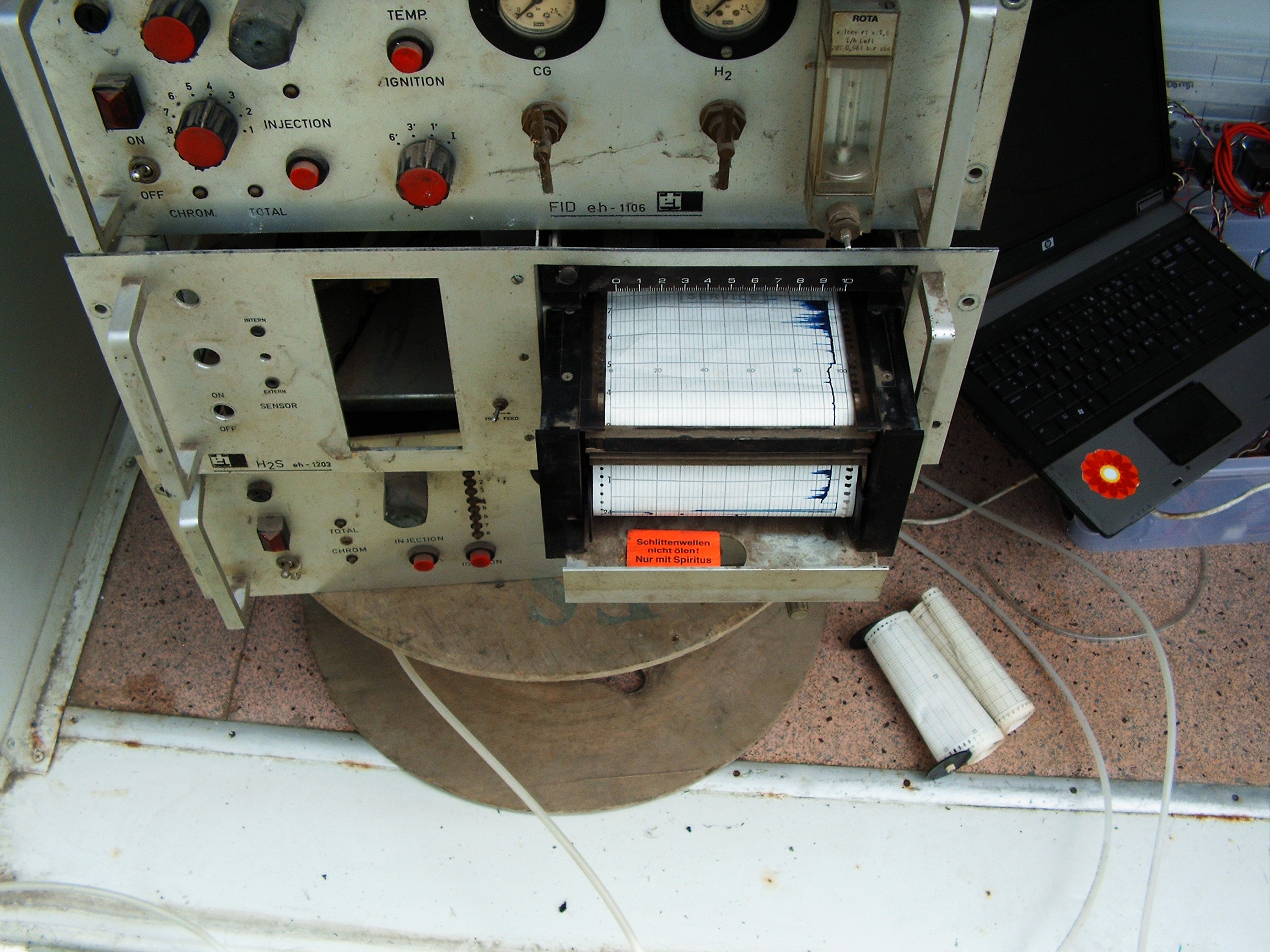
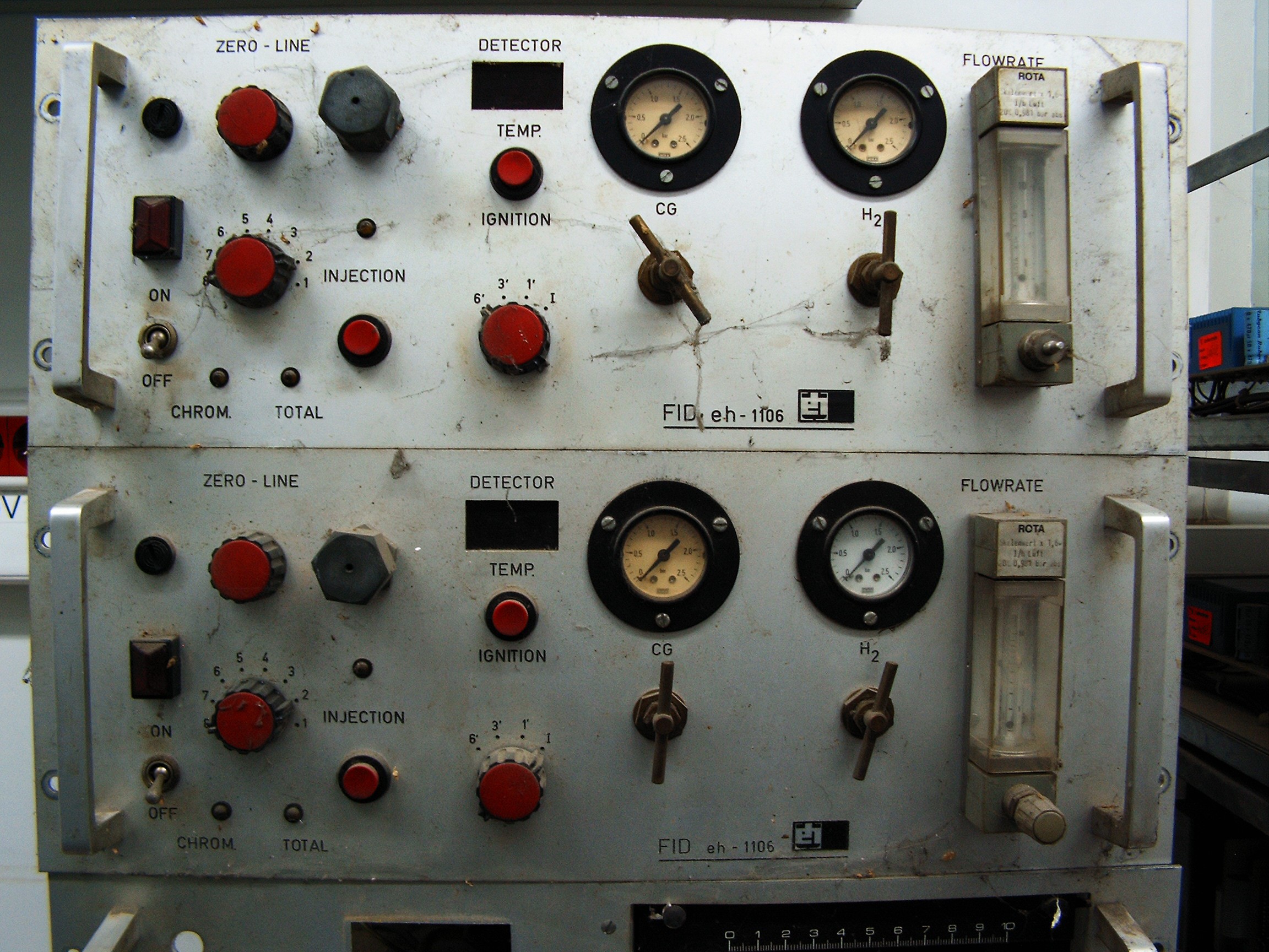
Chromatographs Setup![]()
Spare Chroma and graphic paper recorder. No more FID sensors as the model specifies. Everything is now TCD.![]()
![]()
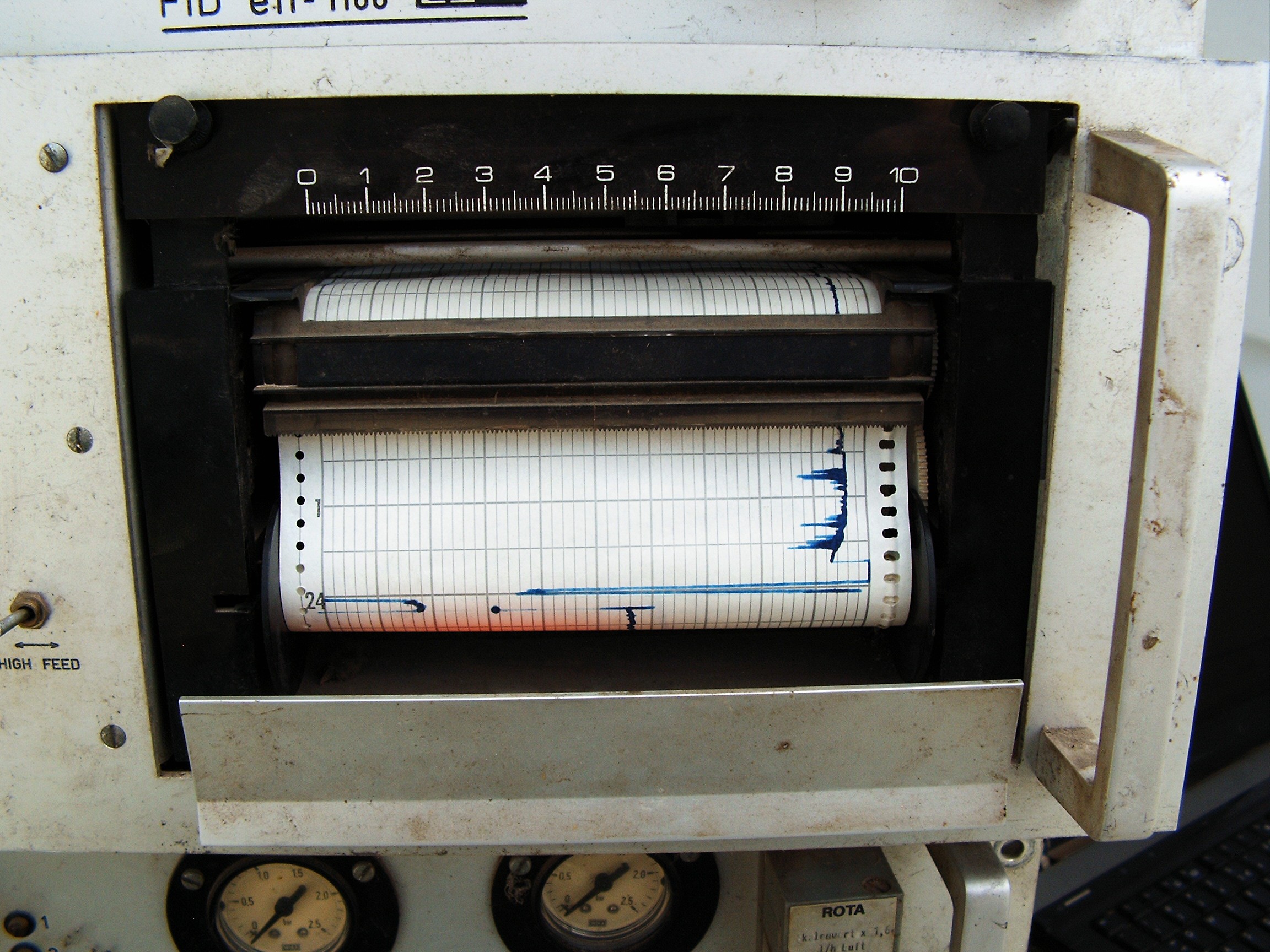
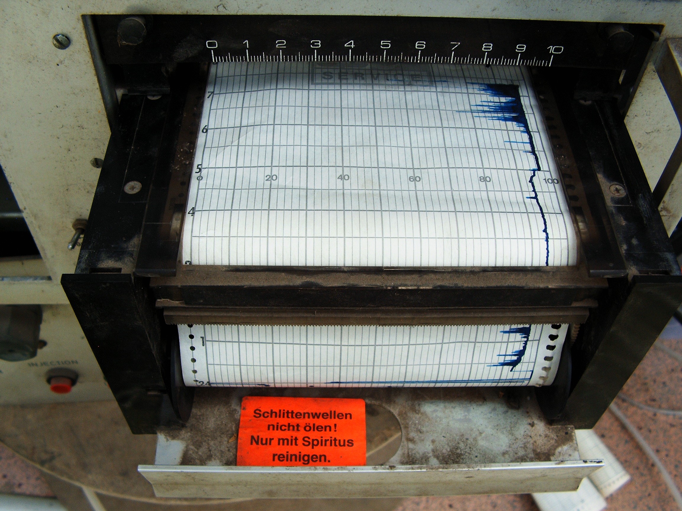
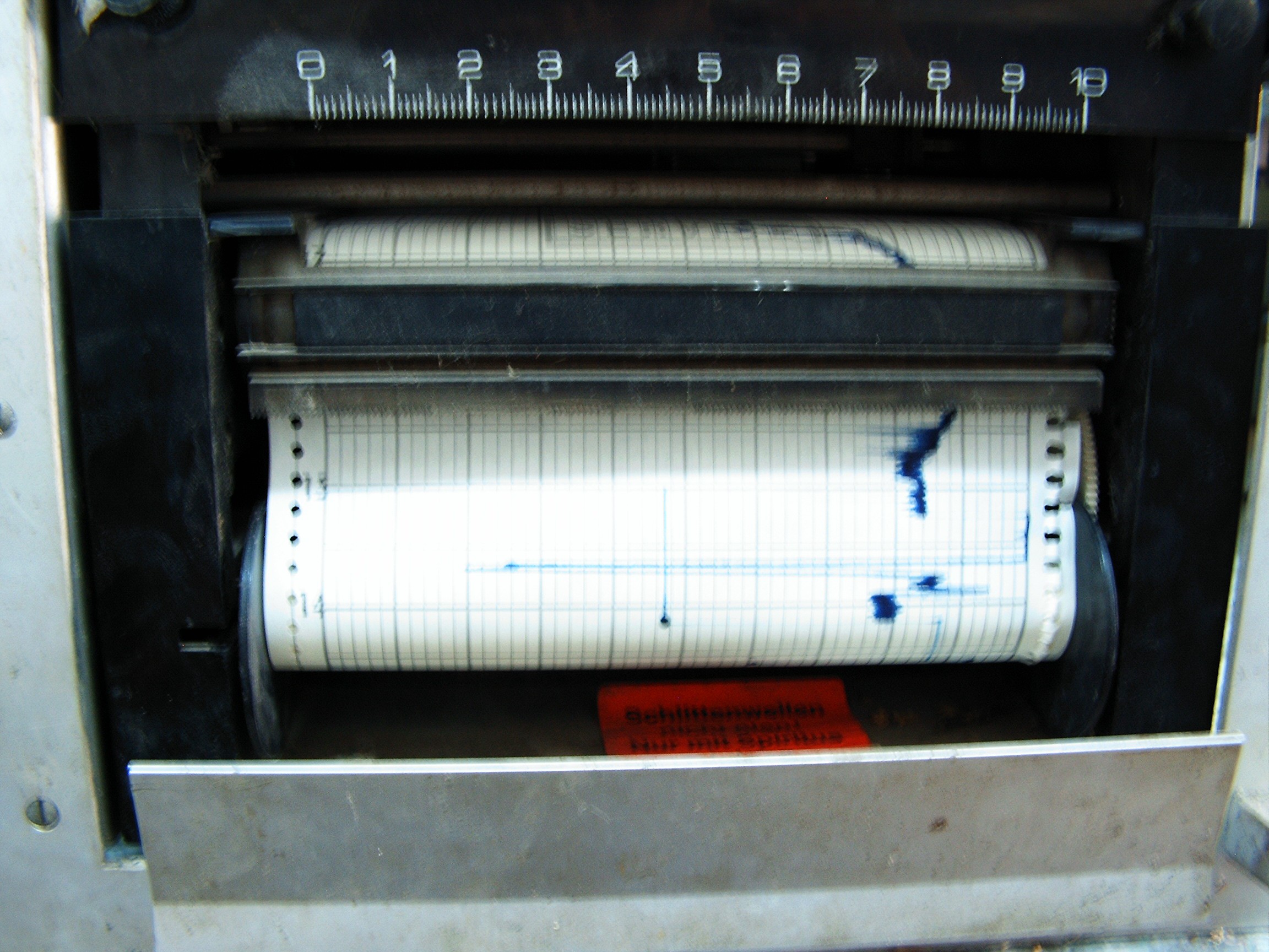
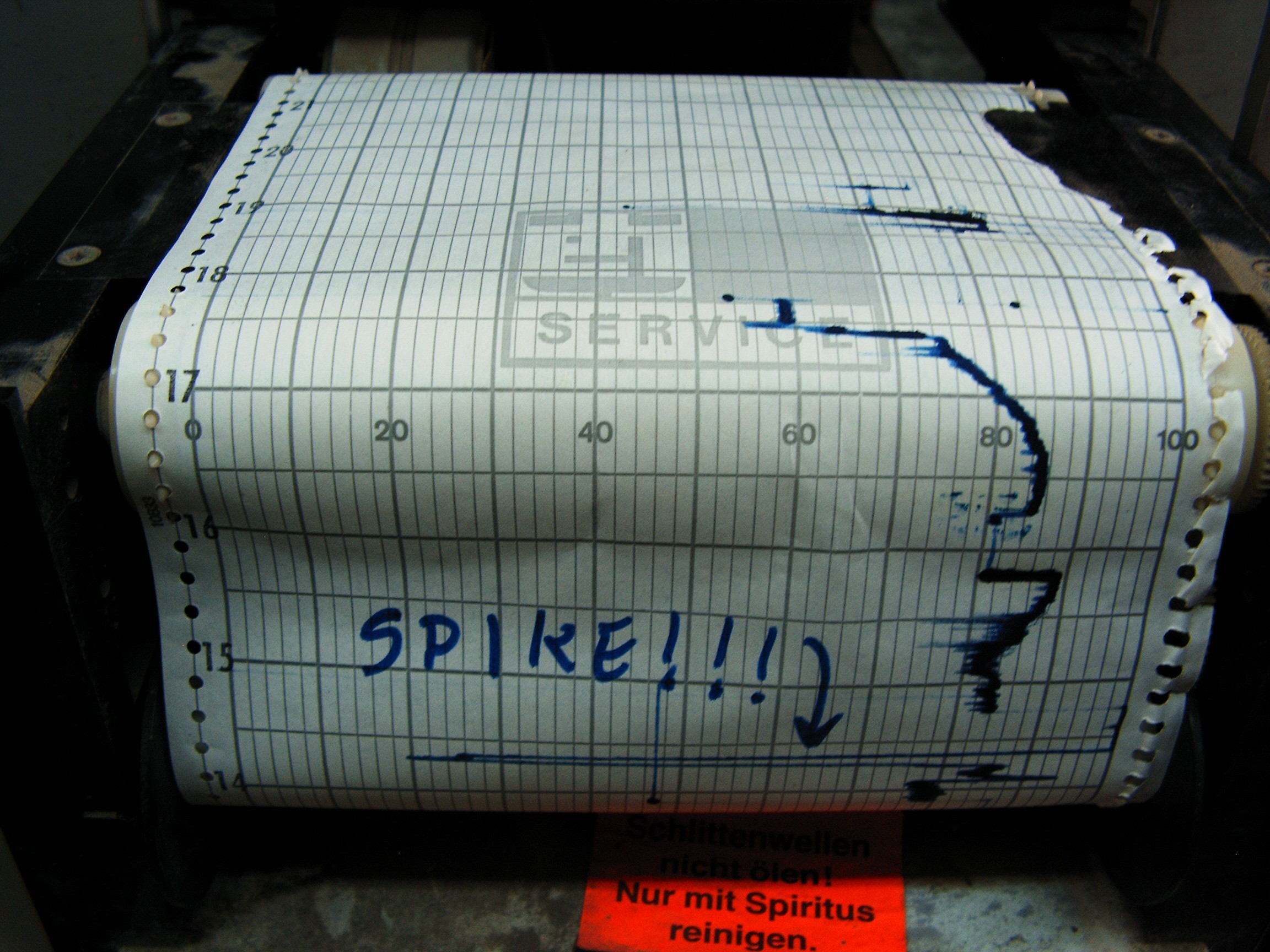
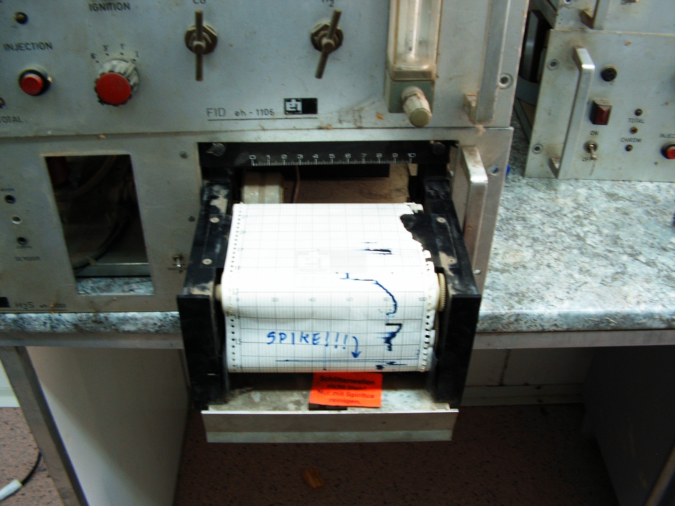
![]() System powered up and warming. Paper graphic recorded loaded.
System powered up and warming. Paper graphic recorded loaded.Right side: laptop running FreeBSD and connected to data acquisition unit.
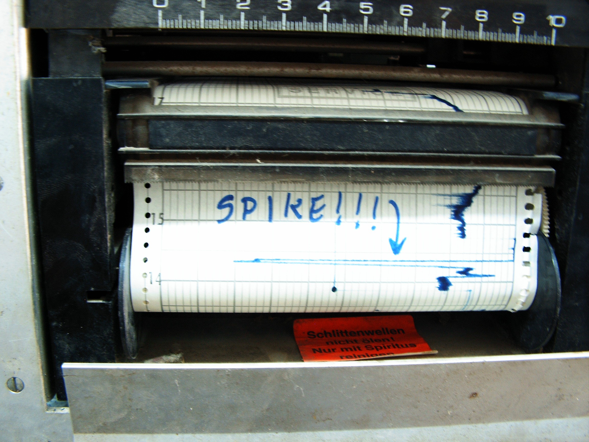
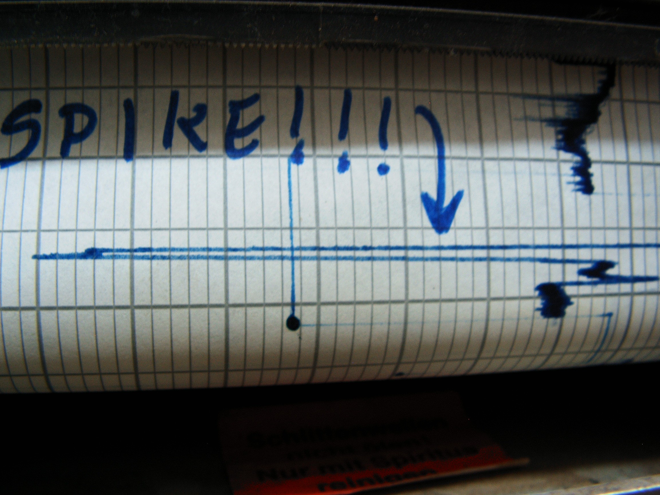
Spike recorded on graph.![]()
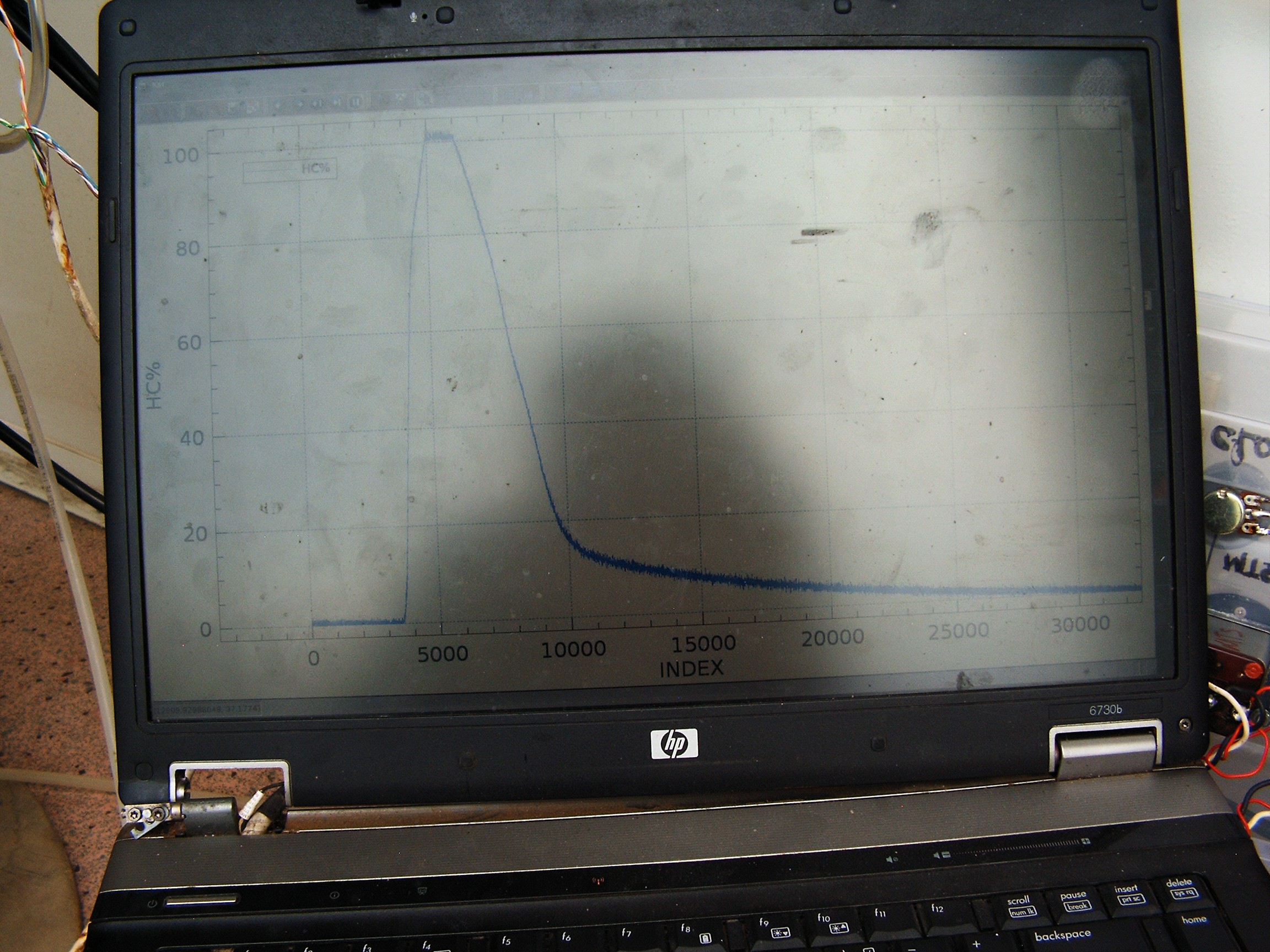
Graphing software on laptop: kst2 + real time data loaded from a file.
C program reads the DAC and outputs numbers in two tab-separated columns.
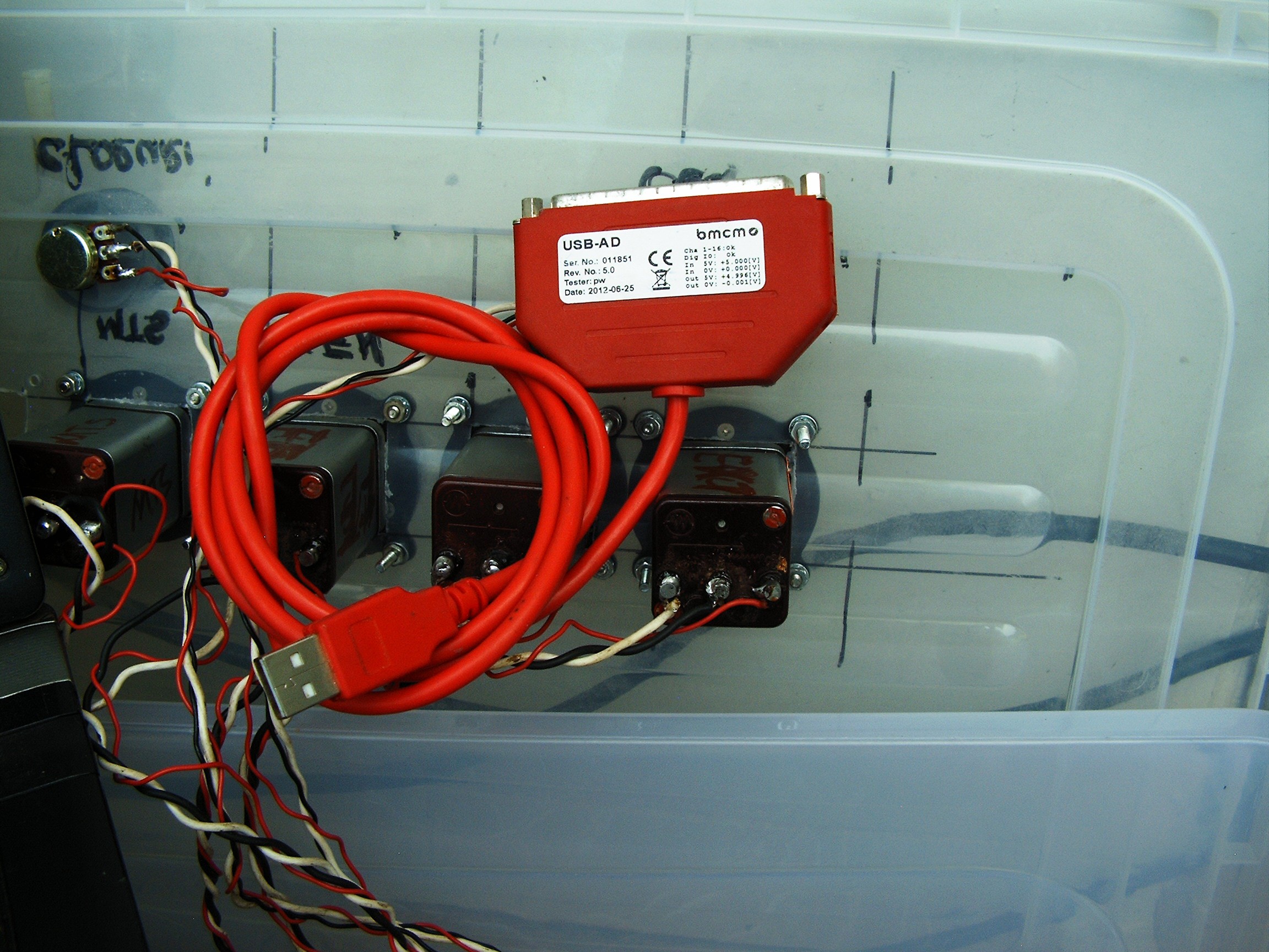
![]()
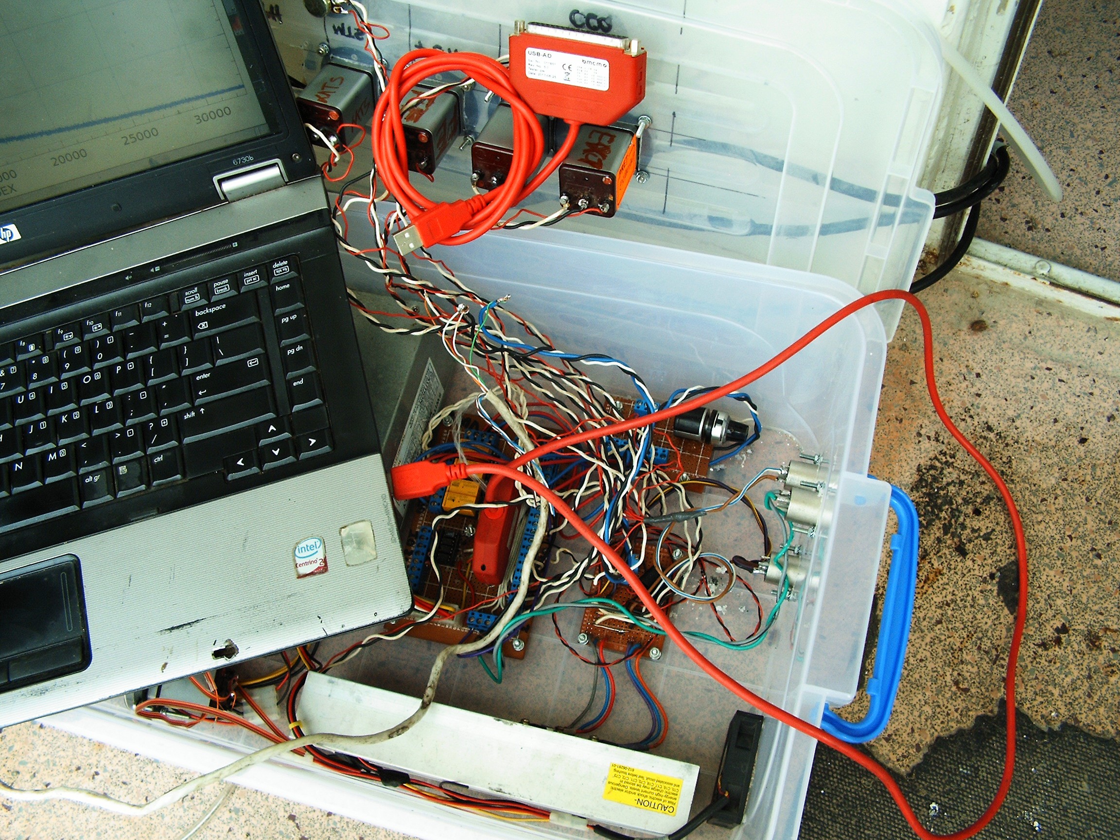
BMCM USB-AD USB Data Acquisition Card. 16 analog inputs, 1 analog output, 4 digital inputs, 4 digital outputs. Works with FreeBSD Unix.
Under the laptop there's the other USB-AD connected to a quickly made adapter.![]()
The connector is DB-37. White cable under the laptop brings the signals from both Chromas.![]()
![]()
![]()
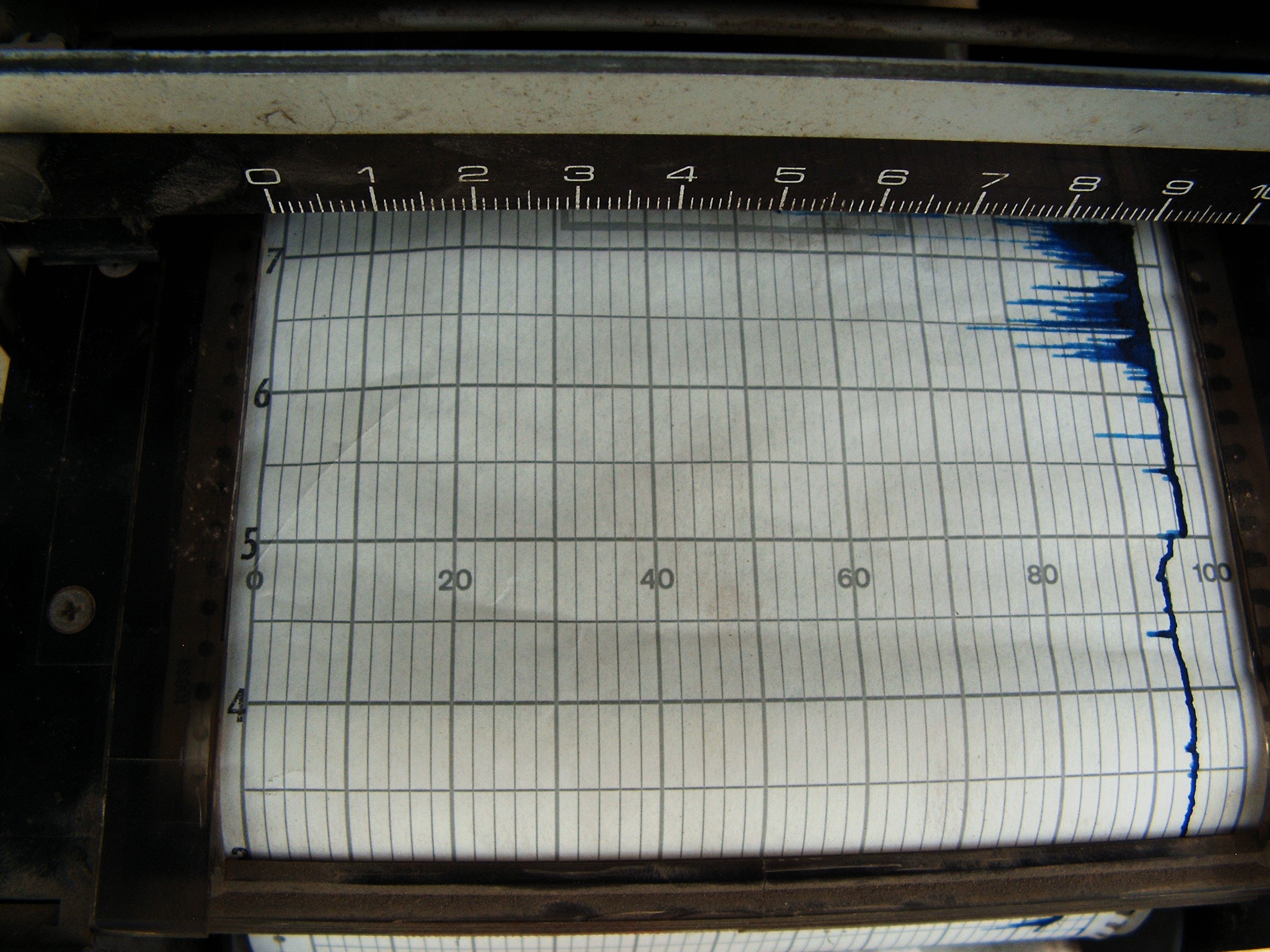
We've got a spike (Air - oxygen, nitrogen) and a lot of noise. After the spike (going from bottom to top) the Chroma says there's a lot of humidity (sudden graph lift-off, slow fall). I think I reversed the polarity of the motor? Graph should start from left side.
Same spike (air) on the laptop. Need to lube the graphic recorder.
![]()
![]()
"Do not oil carriage rollers. Clean with alcohol"
System warm-up....
![]()
.....and BOOOOM!![]()
Magic smoke come out from the main board of the graphic paper graphic recorder, but I managed to save the numbers. So no paper receipts for now. I asked a small girl to graph me the results, she needed some extra cash for some computer school project involving data graphing. I gave her the files, now she's taking care of that. So dual graph will be her work. Not the separate graphs in FreeBSD KST2 which are presented for now.
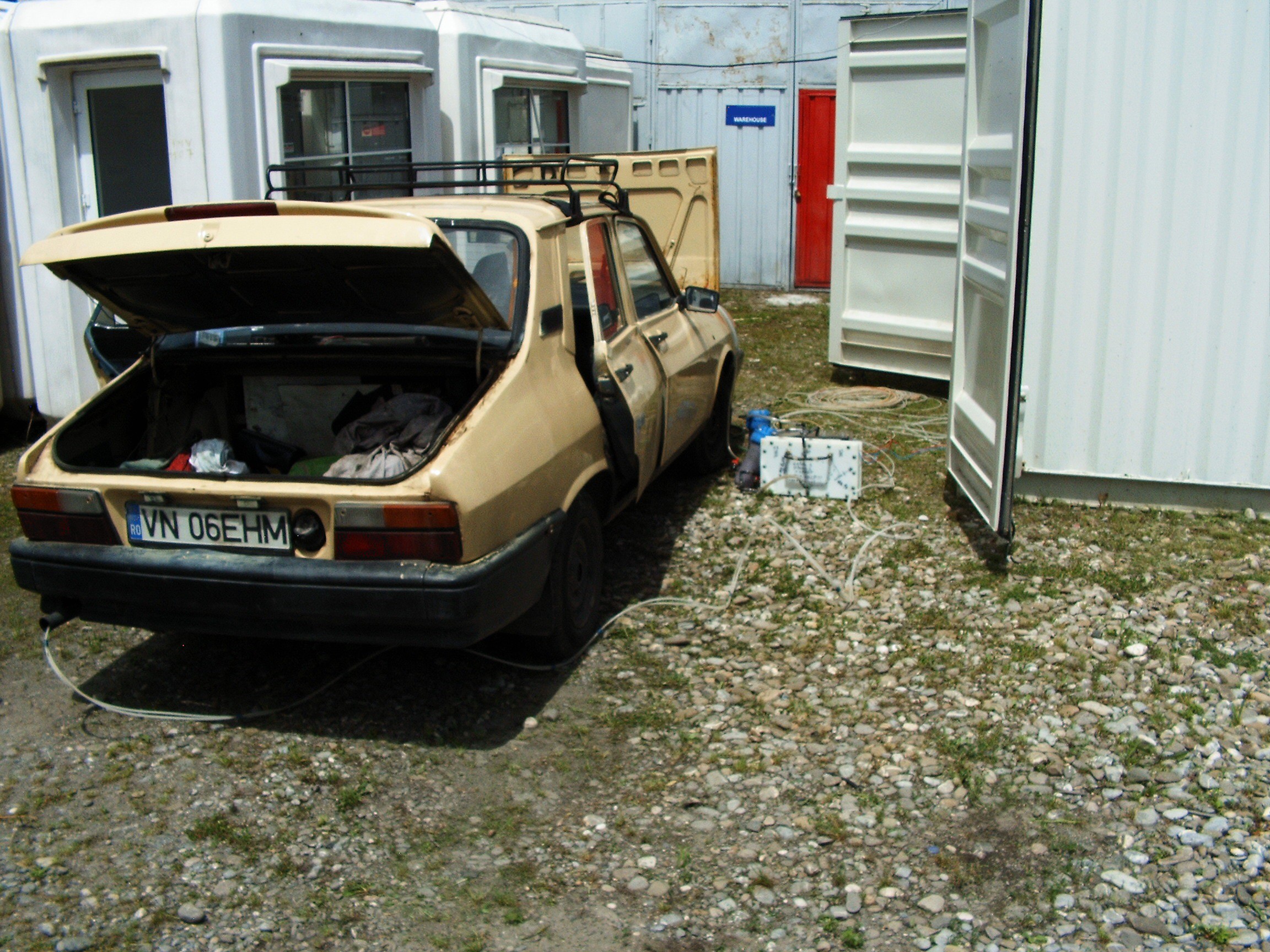
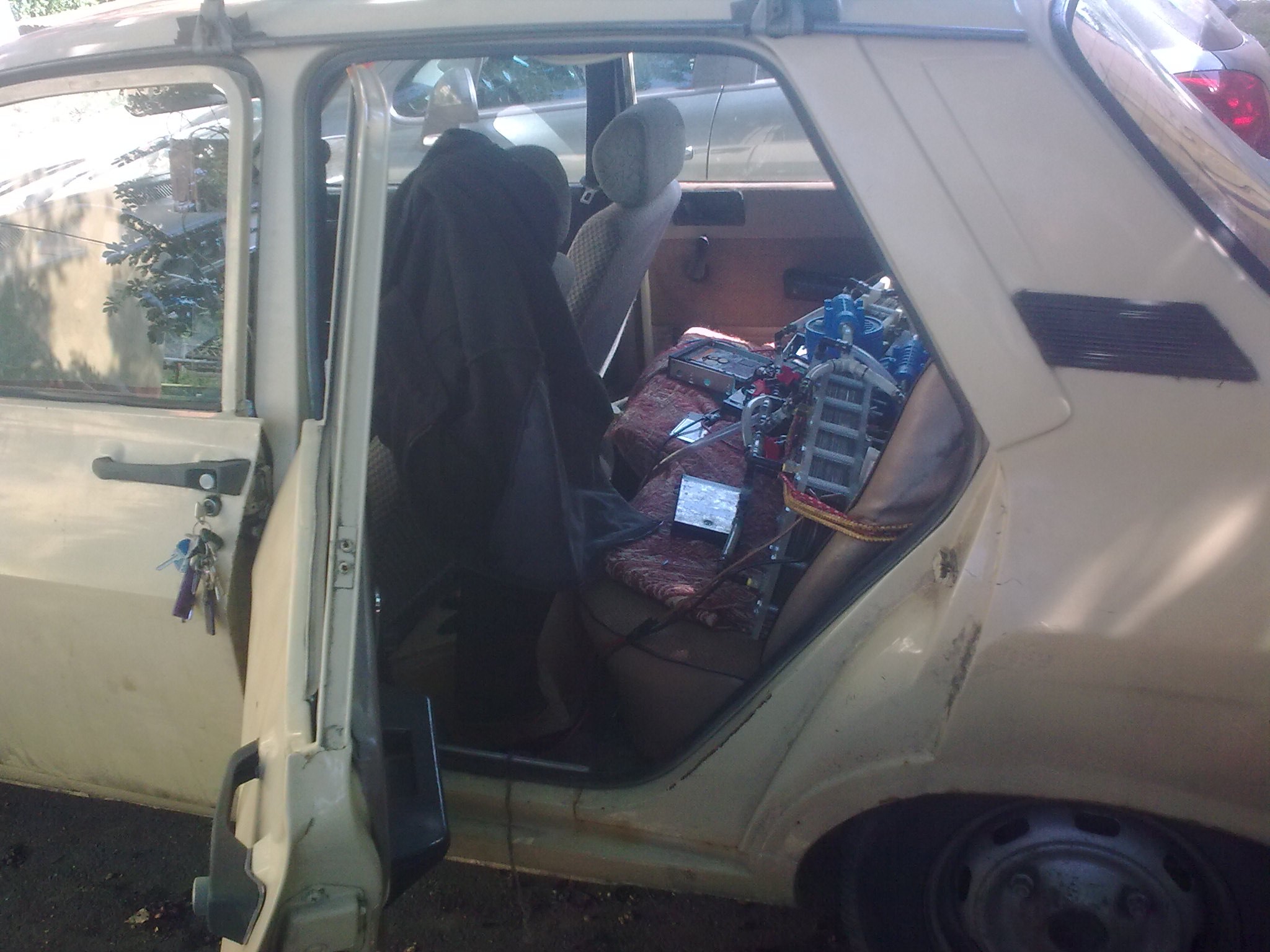
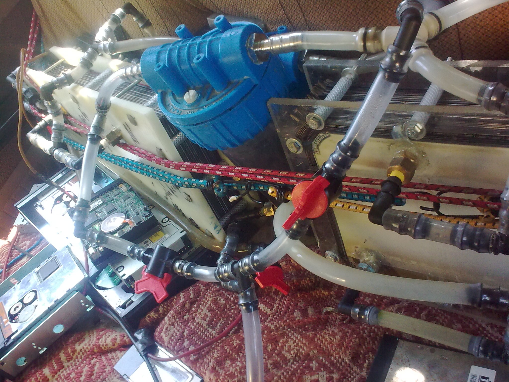
Finally, the car "equipped" with electrolysis reactors:
![]()
![]()
Some hard drives, tape drives and tape cartridges placed to hold everything in place. Those reactors are very heavy, they may break the seat.
![]()
![]()
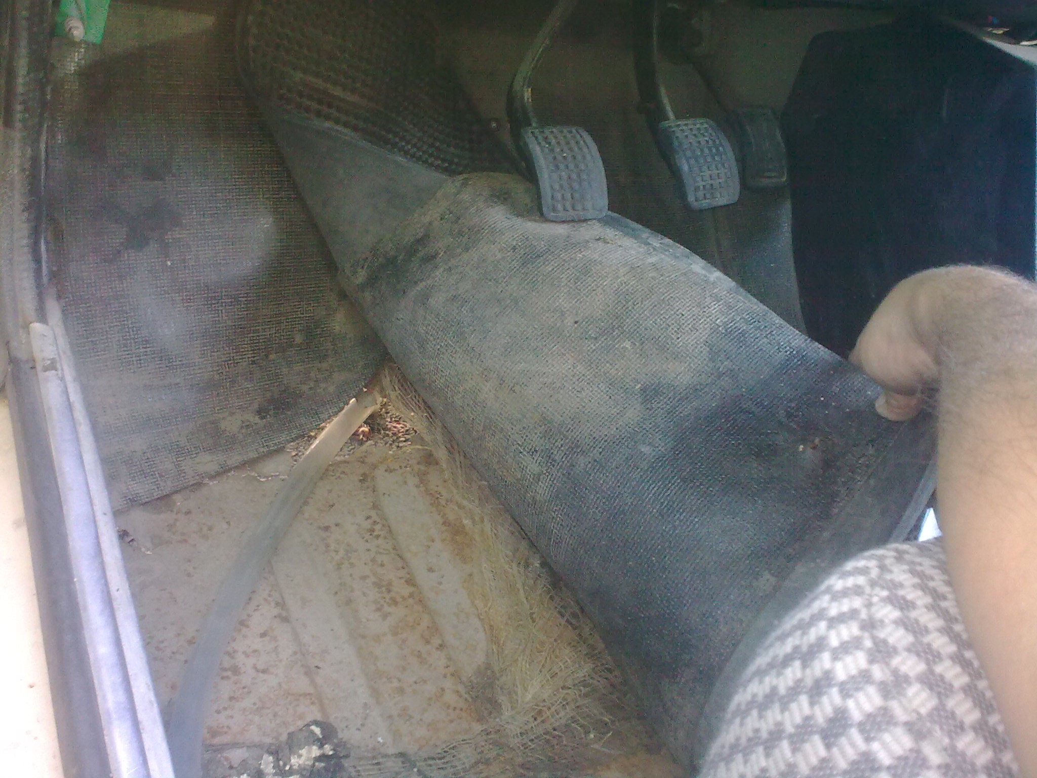
Hydrogen-oxygen hose goes out through a hole under driver's feet....
![]()
and through a third final bubbler streight into the air intake manifold.
![]()
Air intake hose (glove) replaced.
At the base of the carburetor there's the Chroma In gas line.
Need some external electric generator and I can go mobile.
.
.
.
2. Experimental Results
First we need to calibrate both Chromas in order to understand what kind of data they output.
2.1. Normal air measurement
![]()
From left to right
First spike is atmospheric AIR: oxygen, nitrogen;
Second spike is the humidity in the air (water steam)
Third spike is Carbon Dioxide
And these Chromas are weird. Their data do not really match.
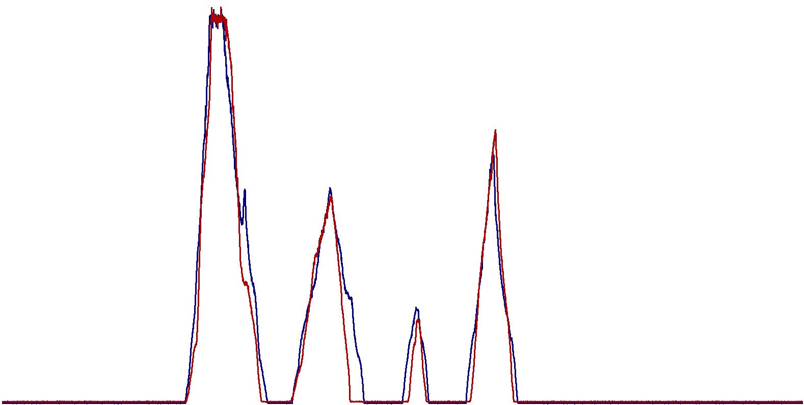
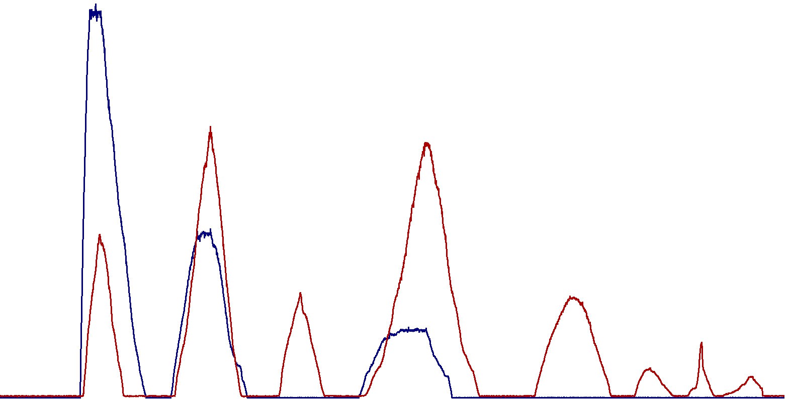
First graph just came out, I think I found a little genius living just next door....
![]()
Blue color is Chroma In
Red color is Chroma Out.
And there are some differences between them..
.
2.2. Normal air and CH4 from some calibration gas tank I found in the warehouse:
From left to right:![]()
- Atmospheric Air;
- Humidity;
- Carbon Dioxide;
- CH4 (last spike).
Second graph just came out:
![]()
.
.
2.3. Normal Air + High End Calibration Gas
High End Gas contains a lot of hydrocarbons, CO2 and Nitrogen.
![]()
From left to right
- Atmospheric Air;
- Humidity (more humidity in Chroma Out);
- CH4 (C1 Gas. The number means how many carbon atoms are in the molecule)
- CO2;
- C3;
- iC4;
- nC4;
- iC5 (iso-pentane);
- nC5 (n-pentane);
- C2 (ethane);
And second graph is out:
![]()
.
.
2.4. Normal Air + Hydrogen Sulphide (H2S)
![]()
Last spike comes out after around 35....40 seconds. That's H2S.
![]()
.
.
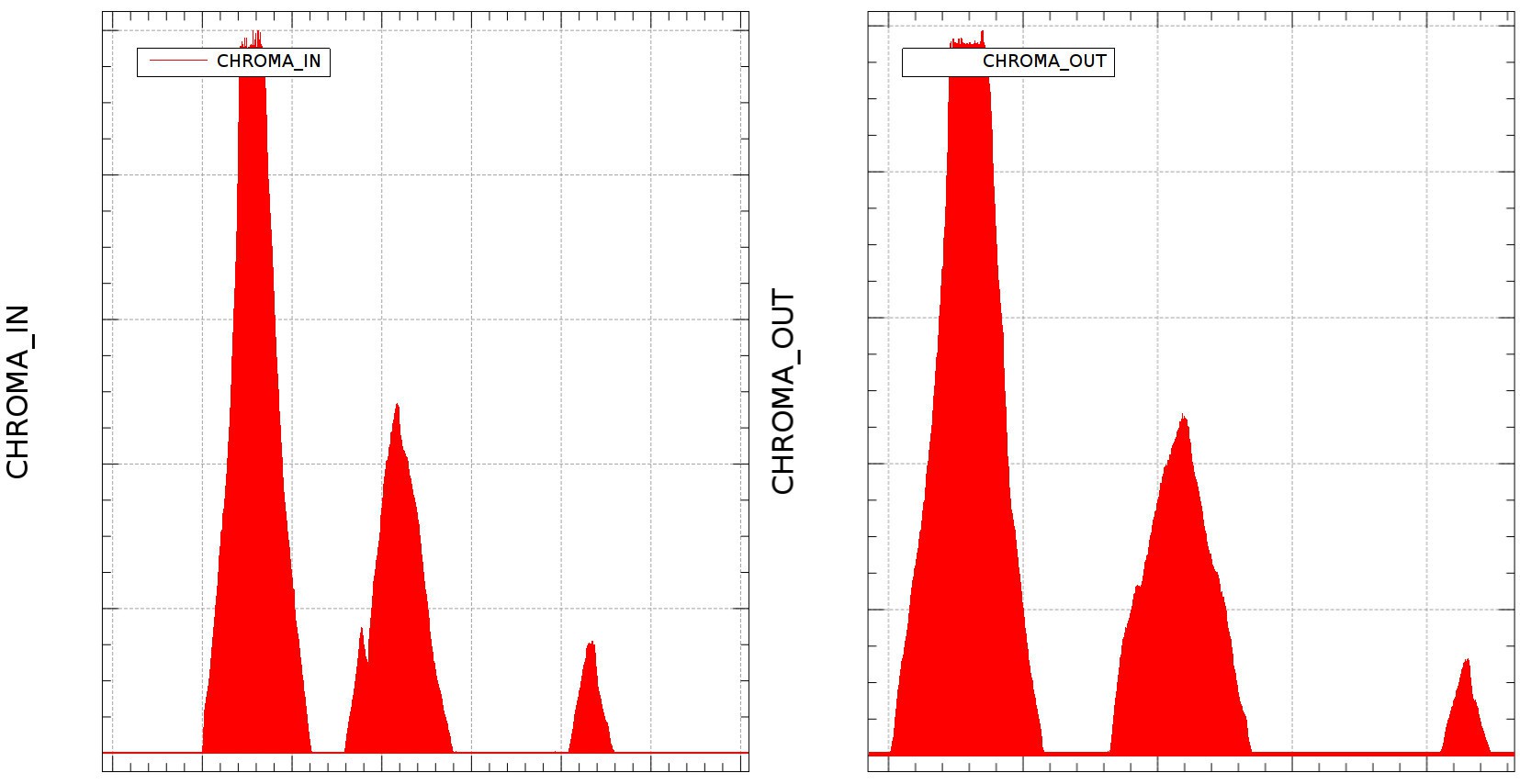
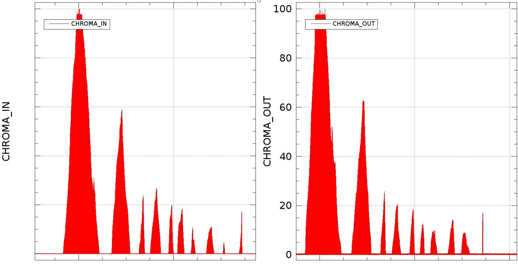
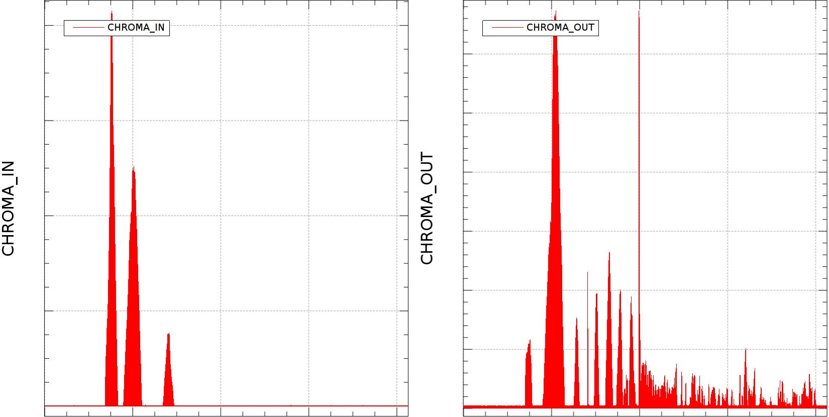
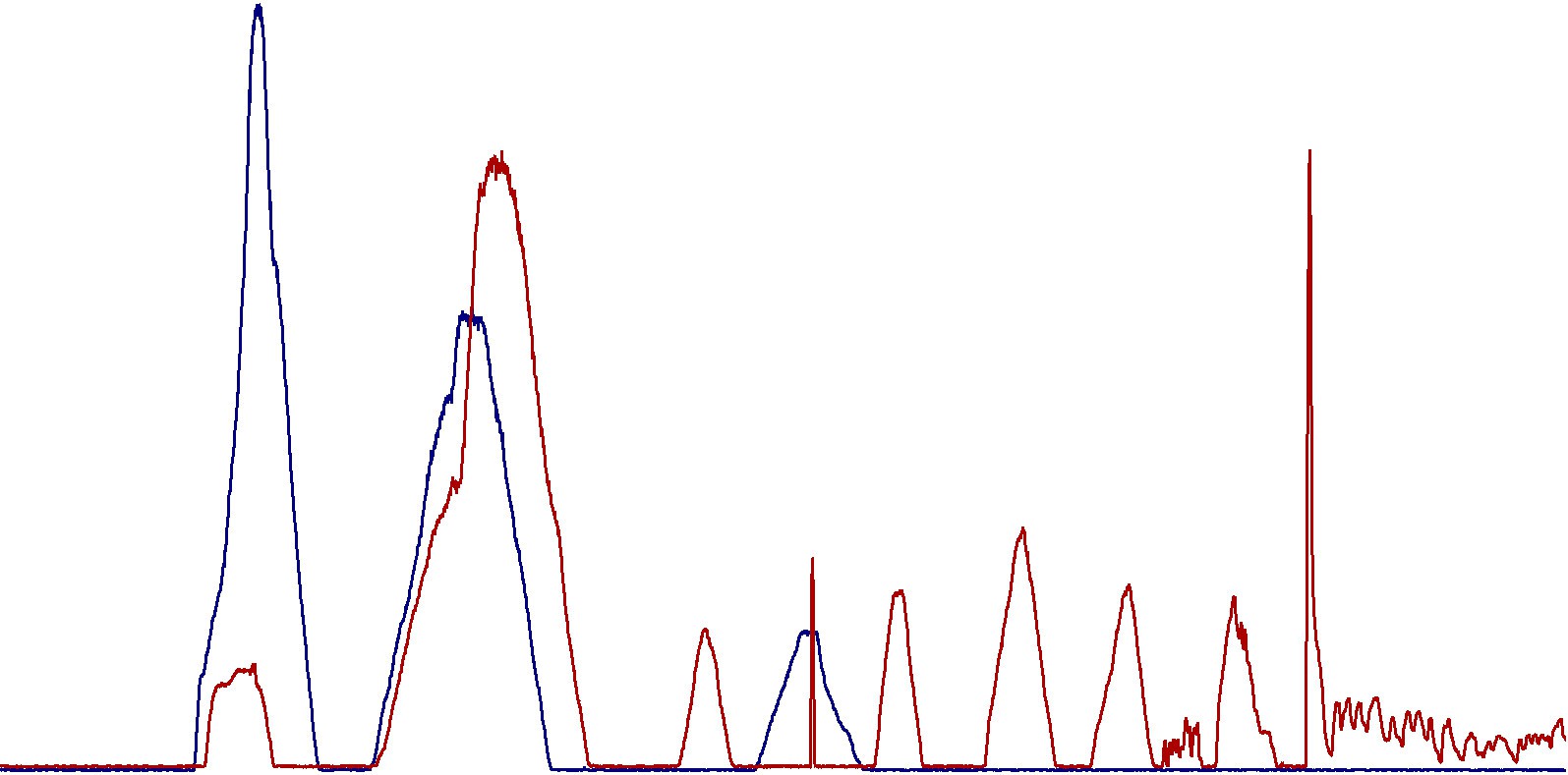
2.5. Engine Intake Manifold vs. Exhaust in normal conditions (no hydrogen)
![]()
We already know what Chroma In shows.
Now - Chroma out, interpretation from left to right:
----> ambient air components:
- 1st spike: Atmospheric Air (lower, that's because the car does not output ALL the exhaust in the Chroma. It also sucks air through the pump.
- 2nd spike: Humidity. A lot of it. Since the Gasoline respects European Union standards, I hope they did not add water in it. Looks like I'm either a victim of counterfeit fuel, or egine's cylinder head gasket is broken and engine coolant is leaking inside the cylinders;
------> hydrocarbons area:
- 3rd spike: Something close to CH4;
- 4th: CO2 is sky high, and I think Carbon Monoxide is also present in the same spike;
- 5th: something close to C3;
- 6th: more hydrocarbons in the area occupied by iC4;
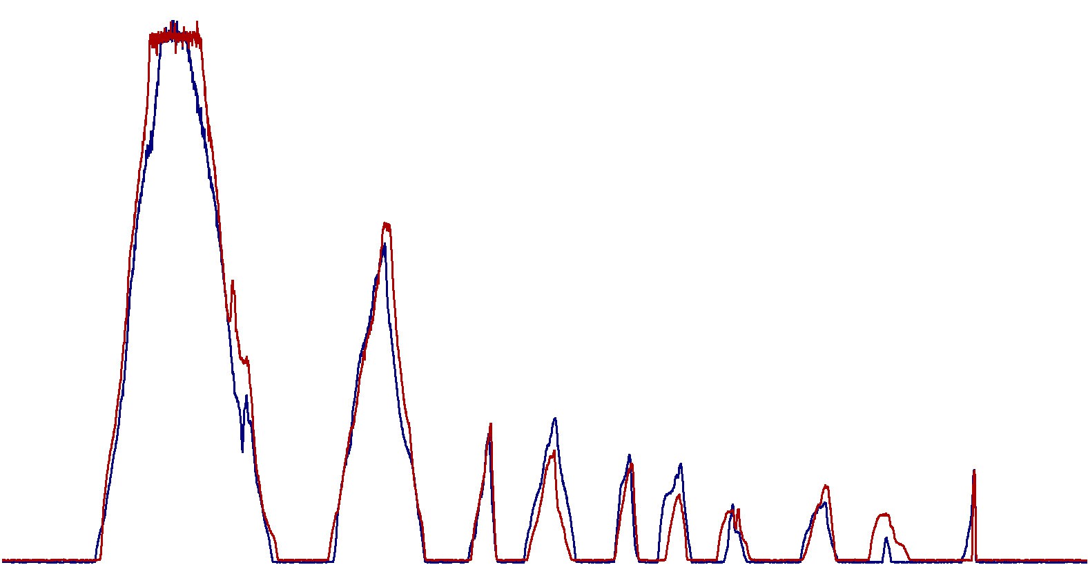
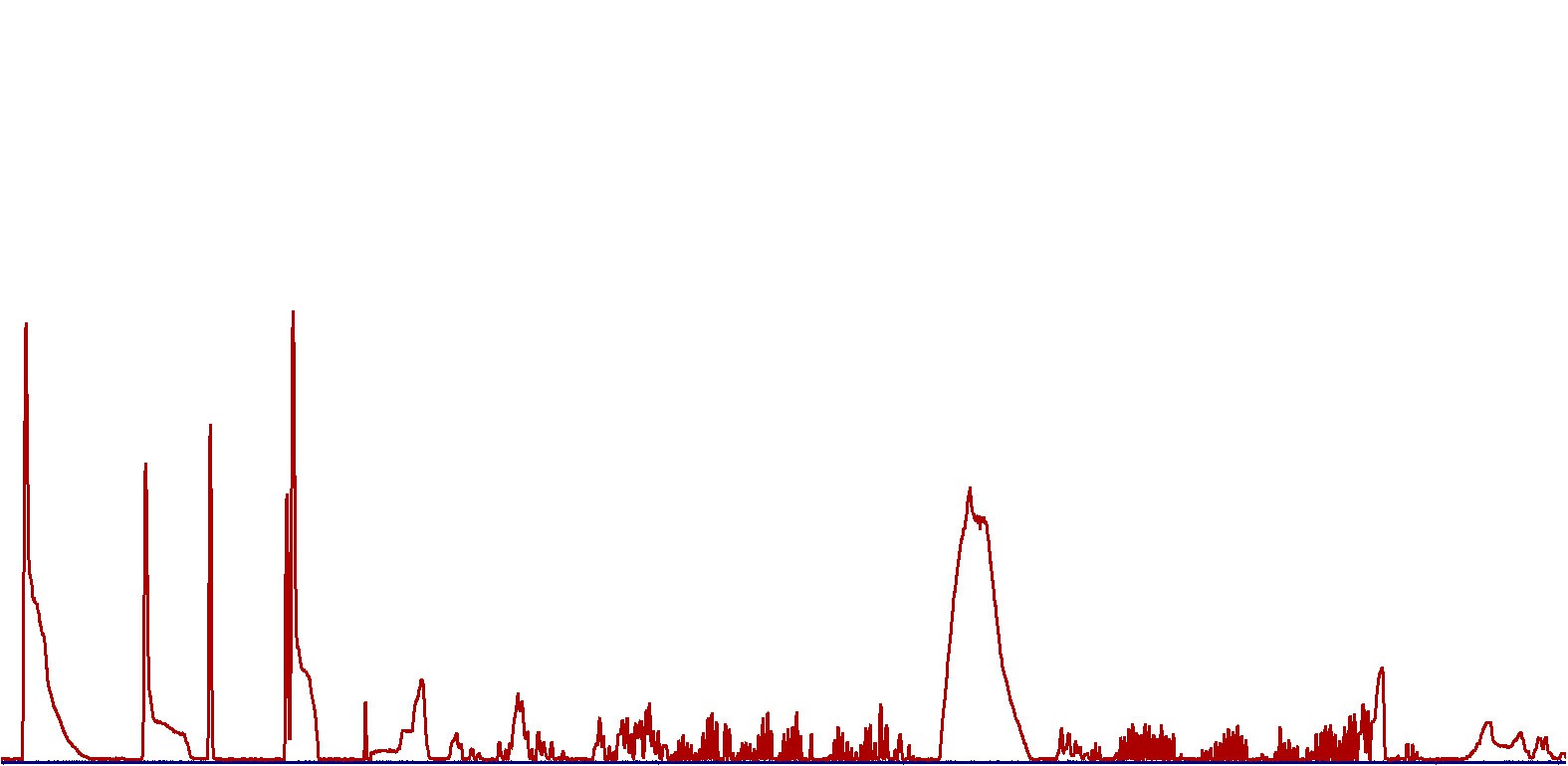
There are some other spikes in hydrocarbons area, and among the last spikes there's something big which came out around the time corresponding to H2S.Detailed combined graph is out:
![]()
Zoomed: Air, humidity, CH4?, CO2(+CO?), C3?, iC4?
![]()
Last big spike - H2S
![]()
Again, H2S shifted left to see the rest.
.
.
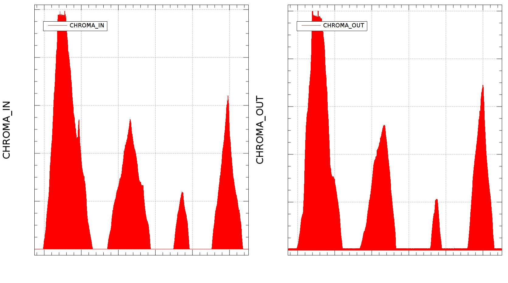
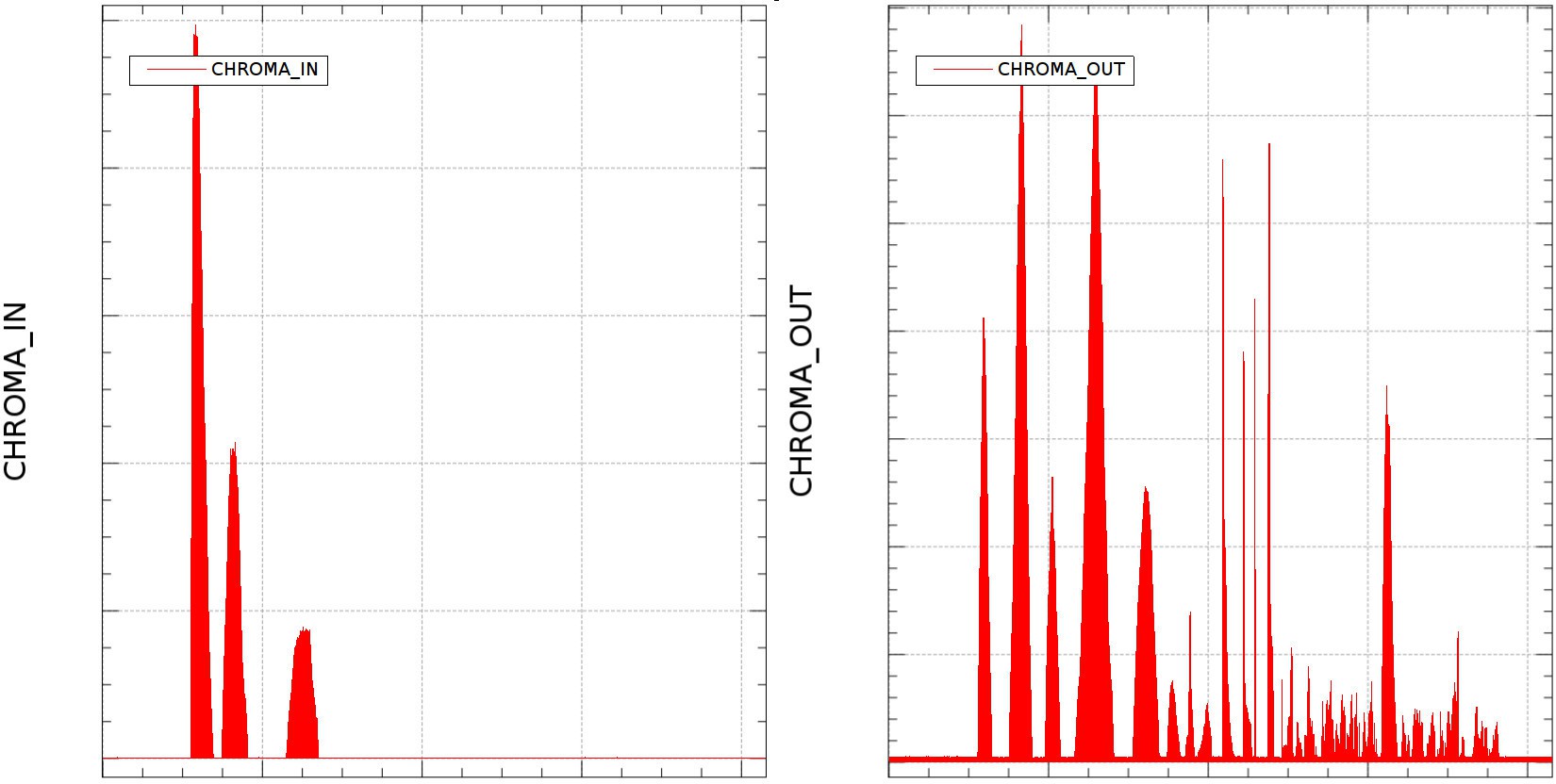
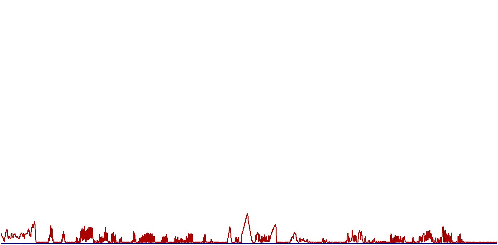
2.6. Engine Intake Manifold vs. Exhaust with added Hydrogen-Oxygen mixture
![]()
Things become interesting here, let's check it out:
Chroma In stays the same. It does not record the extra hydrogen+oxygen intake. It does not influence the Helium carrier gas, so it seems it keeps the TCD sensor filament at constant temperature. Humidity is a little higher than the previous Chroma In measurement, meaning there is some water steam coming out of the reactors;
Instead, Chroma out shows some weird results:
-1st spike (air) gets lower;
-2nd spike (humidity) goes sky high;
- 3rd spike (CH4) is lower than the previous measurement (without hydrogen-oxygen);
- 4th spike (CO2) - it comes as a small burst;
-----> hydrocarbons area:
- components are smaller in amplitude, there's a small burst of something I am unable to identify due to the lack of professional equipment;
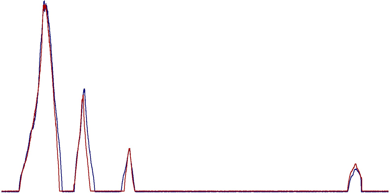
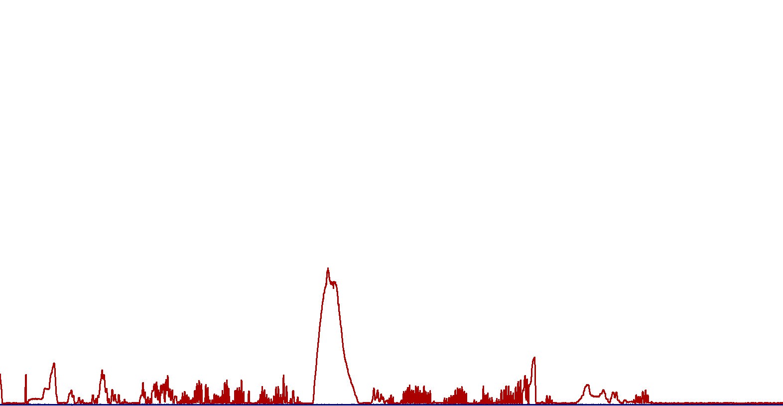
Combined graph is out:
![]()
![]()
The bigger spikes came out starting with t=30s and finishing at t=45 seconds. Is H2S hiding in there? Graph is zoomed.
.
.
3. Conclusions:
According to this ancient tech I managed to rebuilt, and with the help of the theory explained in Science time (II) Reducing exhaust pollution article, I would really really really like to confirm the following conclusions using some professional, latest technology equipment and fresh calibration gases:
- The engine outputs some huge levels of pollution gases;
- Both Chromatographs were calibrated with gases and mixtures used in Petroleum Drilling process, more specific for Mud Logging Cabins Total Gas Detector and Chromatograph;
- Adding Hydrogen (+oxygen) mixture in the air intake manifold of ignition-based engines leads to reduction of Carbon Dioxide;
- I am unable to see any Carbon Monoxide spike, so I assume this gas is recorded in the same spike as Carbon Dioxide;
- Chroma Out graph is ugly during normal automobile engine operation, and it gets "cleaner" in the last case - when using hydrogen-oxygen mixture addition in the air intake manifold;
If this data is CONFIRMED by a THIRD PARTY to be valid, then this method can be successfully used to reduce pollution in big big cities - as a transition from traditional automobiles to hybrid, then fully clean means of transport.
This means cleaner streets, cleaner air, more trees, less cancer caused by smog, less problems in child birth - autism, cancers, malformations, low IQ, all the problem that Medical Doctors PhDs know and explain better than a System Engineering PhD, and people in important positions ALWAYS chose to IGNORE for whatever reasons.
[END OF TRANSMISSION]
______________________________________
kernel panic: improbability coefficient below zero
-
Science time (III) Giving second life for an ancient Gas Chromatograph
06/09/2016 at 11:57 • 2 commentsGreetings, fellow hackers.
Now I (really?) understand the philosophy of the jury. Push everyone to hack more. If you have success with your project, push for more and rise up. If you fail, push for more and rise up. Never give up. Never let yourself go down. This is the true hacking philosophy: if you fail, or you are pushed away to give up, nobody cares. There will be other people ready to take your place and push further for nothing.
Instead of receiving some bucks in order to get access to latest tech, now I must hack my way to the 3rd round prize by resurrecting some ancient tech dinosaur in order to get things done.
So from this moment I am no longer questioning the second round results.
Allright, Science time.
I need to "smell" the exhaust gases from the engine in normal working conditions and in the presence of hydrogen-oxygen mixture injected through the air intake manifold.
And for that I need a Chromatograph, so let's see what this device does and how it works.
This is a block schematic of a generic Chromatograph:
![]()
A light gas is used as a sample carrier - usually Hydrogen (flamable!) or Helium (preferred). The sample is injected before the column (some long metalic hose) which is supposed to be heated. Heat can also be applied to a second column (not shown in the figure). The column hose is extremely thin - with microns in diameter. Lighter gases come out first, heavier gases come out later. There is also some theory about gases being attracted or repelled by the column internal coating, which also influences how fast they are separated and how fast they travel through the column. The sampling time lasts for minutes, then the TCD (thermal conductivity detector) or FID (flame ionization detector) outputs some analog signal at a corresponding time, which is the percentage of compound (separated) gas coming out. The higher the spike recorded on the graph, the higher the concentration of that separate compound is. The later it is recorded, the heavier the gas is.The most common sensors (detectors) are as following:
TCD - thermal conductivity detector. If some gas passes around a electrically heated tungsten filament, its temperature modifies (usualy increases) and its electrical resistance also increases. The carrier gas alone (helium) has high thermal conductivity and keeps the filament cool, maintaining an uniform electrical resistivity. When the carrier gas brings a foreign gas, resulting gas mixture thermal conductivity decreases so it does not allow all the heat to dissipate (as before) and forces the filament to get hotter. Its electrical resistivity increases and the corresponding current variation is recorded as a response.
FID - flame ionization detector - it has two electrodes placed close to a flame fueled by carrier gas + air (in this case - hydrogen). This detector is used to identify the presence of hydrocarbons, so these are pyrolized by the flame. The hydrocarbons will split into ions (at cathode) and electrons (at anode) which generates a current between the elctrodes. It does not work with other gases (non-hydrocarbons) as these are unable to pyrolize.
Both sensor responses are recorded as spikes on a graphing device, which form a Chromatogram of the sample gases analyzed.
There are also catalytic sensors, infrared sensors, mass spectroscopy detectors and a lot more. All detect gases in their way but the output is recorded as spikes.
That's it. Simple in theory, headache to build - or to pay for an expansive one.
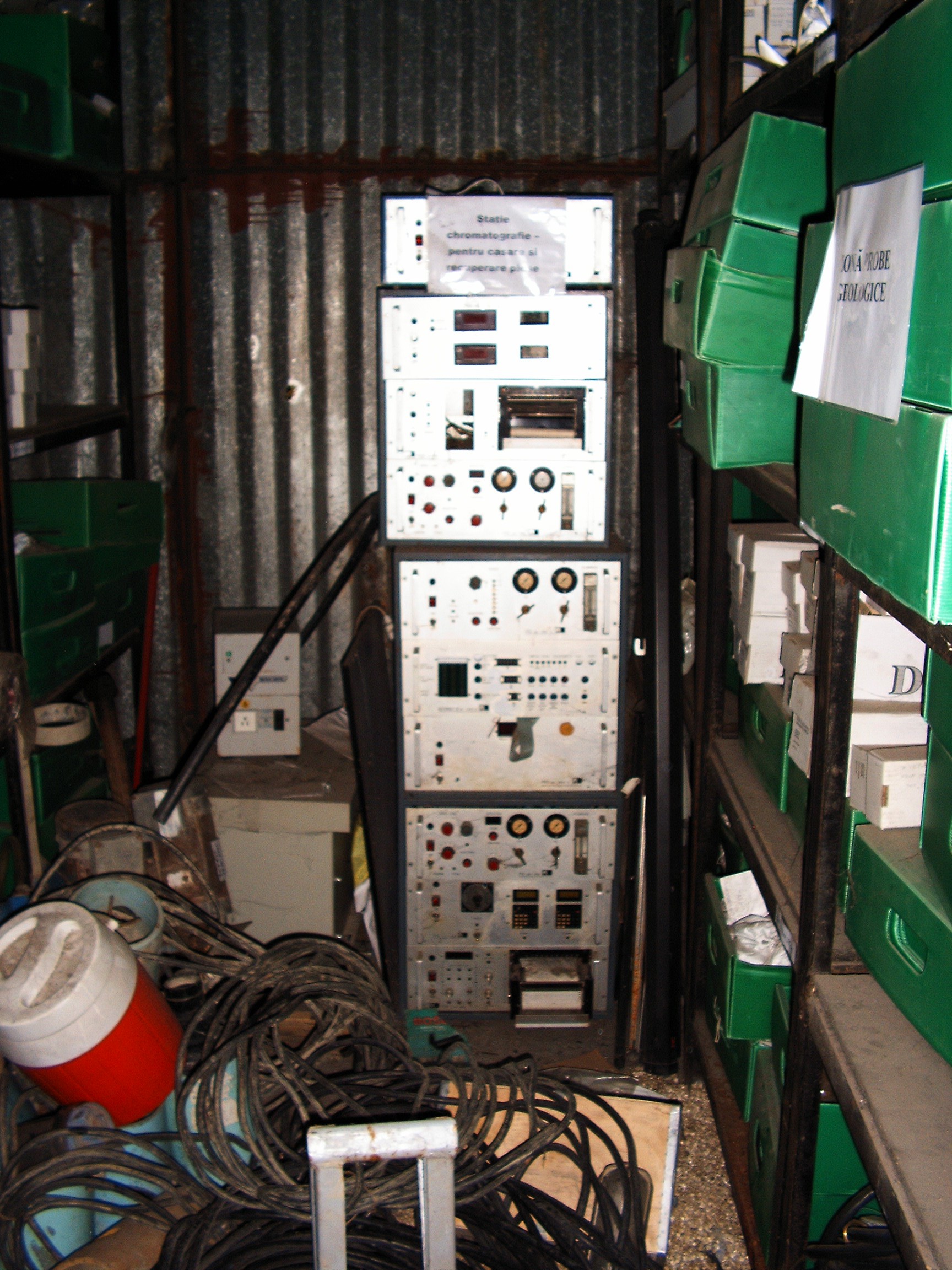
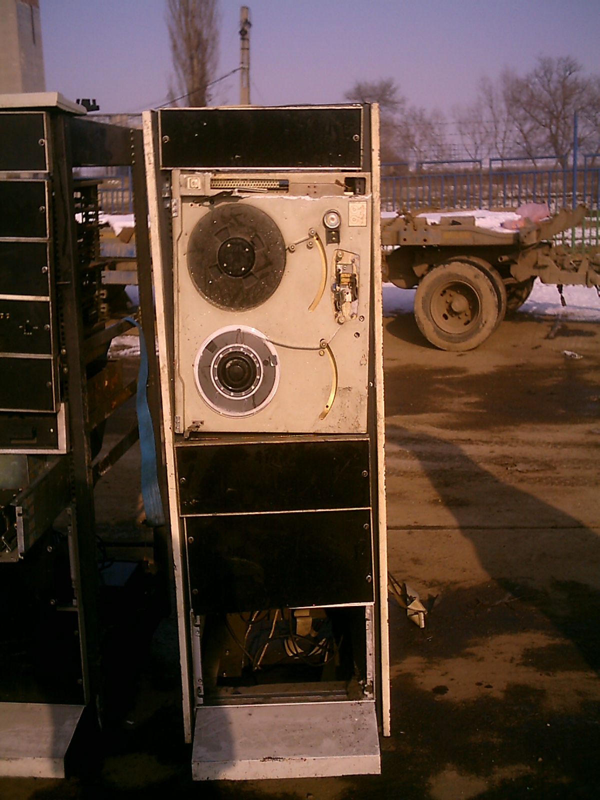
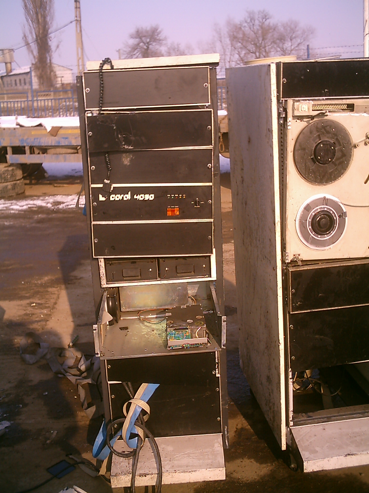
As I announced yesterday on #Hacker Channel, I found a 40-years old Chromatograph Station inside an abandoned warehouse at my work place. It's a true monster. They told me it worked with vacuum tubes and it's entirely trashed. During immemorial times, many generation of rats made it their home....
![]()
I'm happy the camera cannot record the horrible smell.
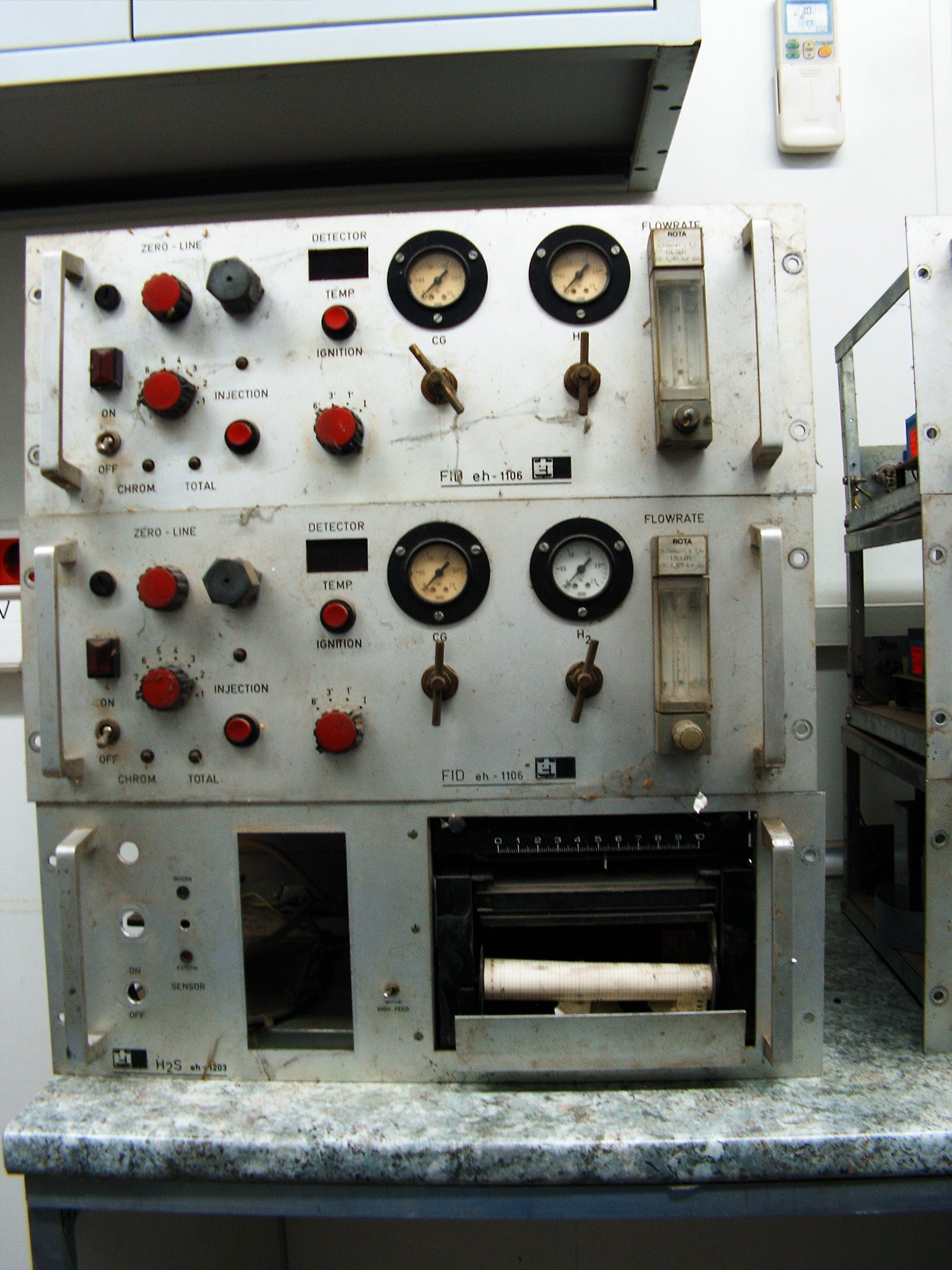
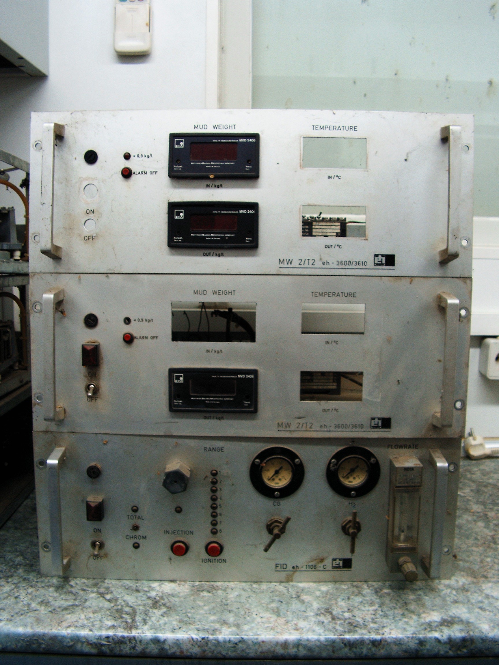
From top to bottom:
- Hole Depth display;
- Mud Temperature in, Mud Density in, Mud Temperature out, Mud Density out (there's a special prepared mud circulating through the drilling hole);
- Paper recorder 1 for Chroma 1;
- Chromatograph 1 (gas in - quantity of gases present on mud before it enters the drilling hole);
- Chromatograph 2 (gas out - quantity of gases the mud brings from the bottom of the hole);
- Mud Pressure Display Unit;
- Some unit full of rat poo;
- Chromatograph 3 (spare/backup);
- Calculation Unit containing two mathematics calculators and an alarm buzzer;
- Paper recorder 2 for Chroma 2. FULL OF RATS. Everything is trashed inside, nothing can be recovered. Not even the rats, they became aggressive when I invaded their home. There's a horrible smell I do not wish to describe. Public toilets smell nice comparing to that.
![]()
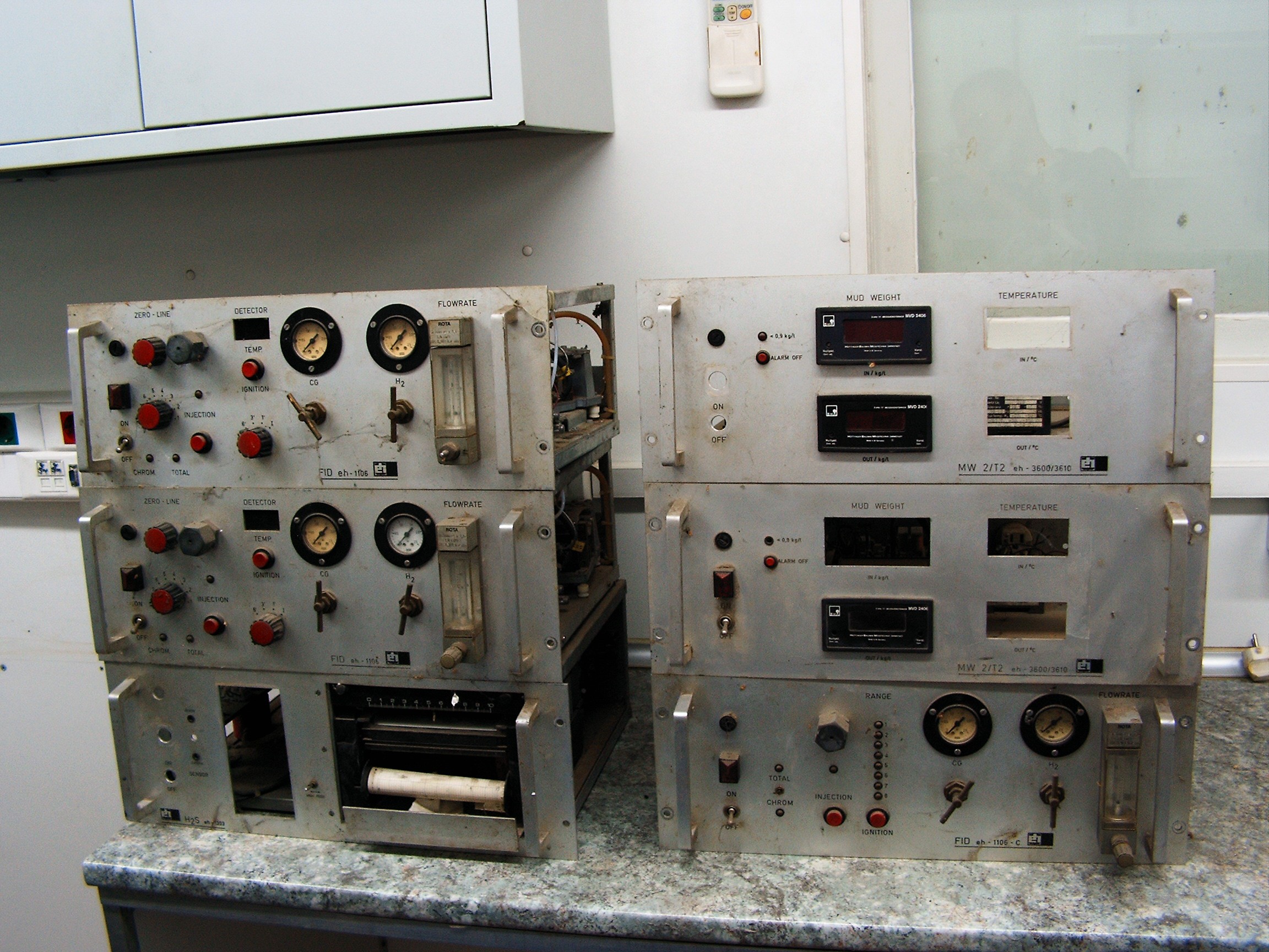
I brought in my office the three Chromas, a paper recorder and two mud weight (density) - mud in and mud out. The smell is unbelievable. Colleagues ran away and told the boss I turned the office into a piggery, again. Nobody allowed me to bring the rest of the system inside.
Chroma 1, Chroma 2, Paper recorder which was supposed to log someH2S variations.![]()
Mud Weight units + spare chroma![]()
Spare Chroma is trashed by the rats. They ate most of the hoses and left a lot of garbage and droppings. Maybe I can scrap some components. I'm happy there are no vacuum tubes in the whole system. It's less dangerous when I will try to power it on.![]()
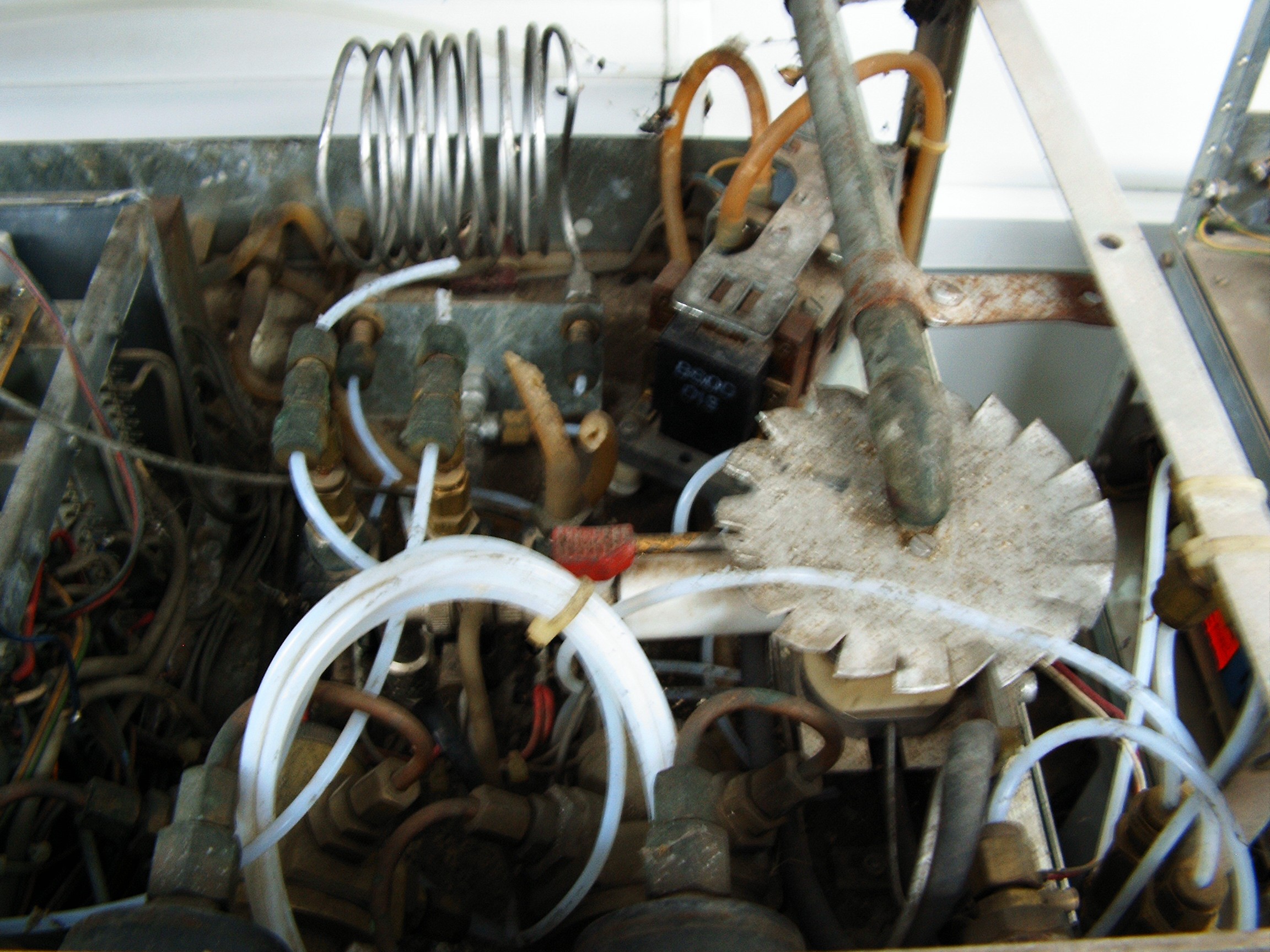
The column is that spiral metallic hose.
![]()
Gas Column is missing in Chroma 2. Recovered from Spare Chroma.
Chroma 1 and Chroma 2, before surgery.![]()
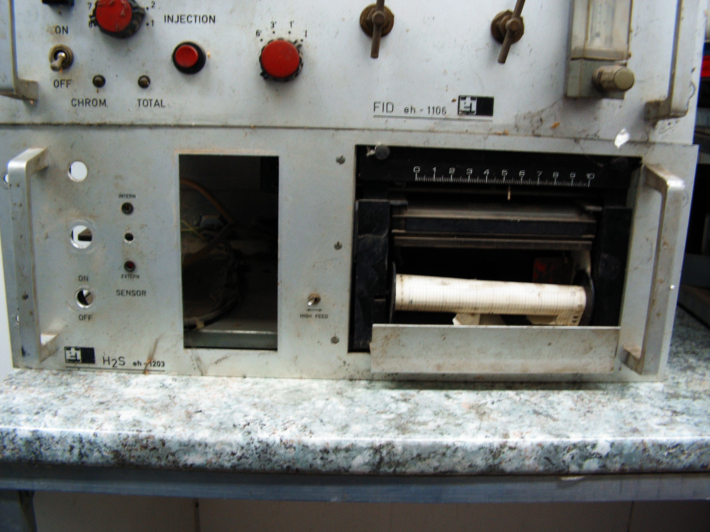
Trashed paper recorder. Also needs surgery.![]()
Hydrogen Sulfide (H2S) sensor. I removed it from the circuit. Need information from both Chromas to go through its electric connections.![]()
Trashed power supply was removed from Chroma 1 and Chroma 2.![]()
They were destroyed by rats. I don't want people to feel sick so no pictures of them. Only by special request.
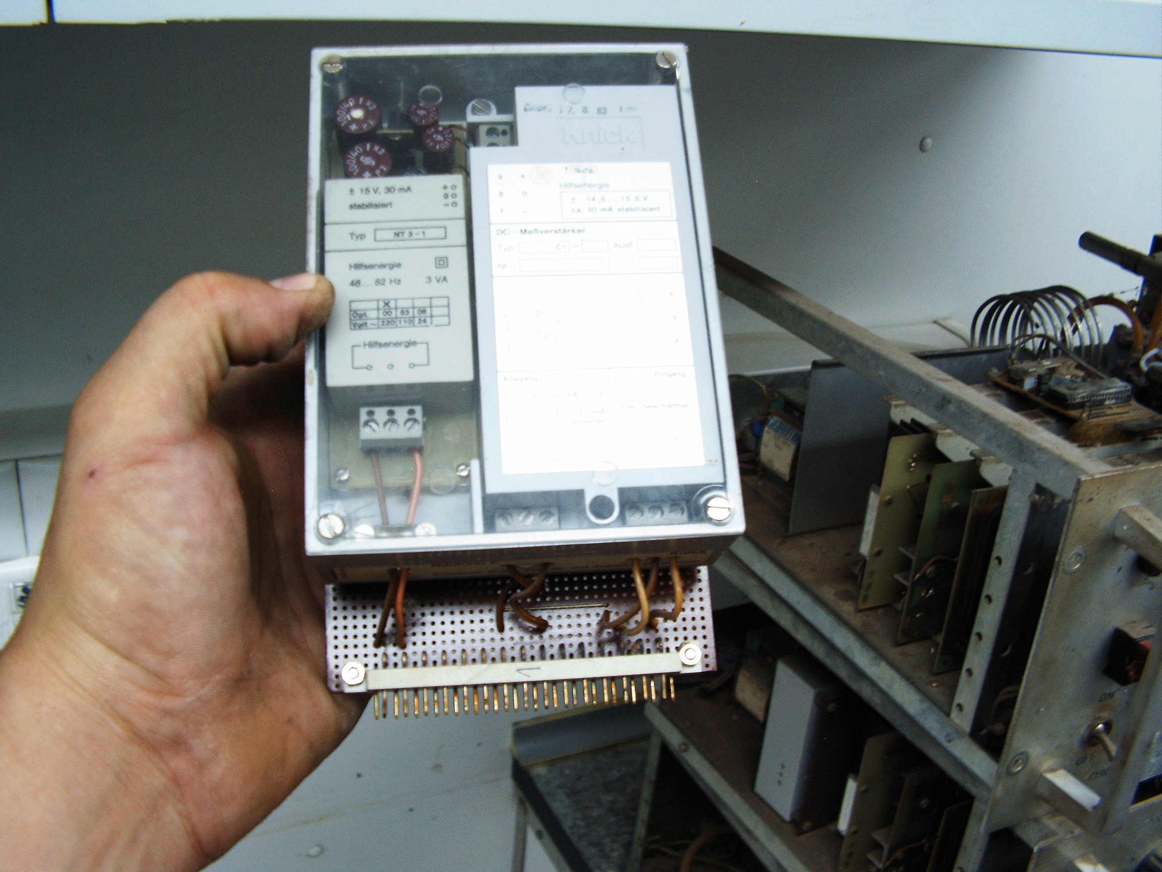
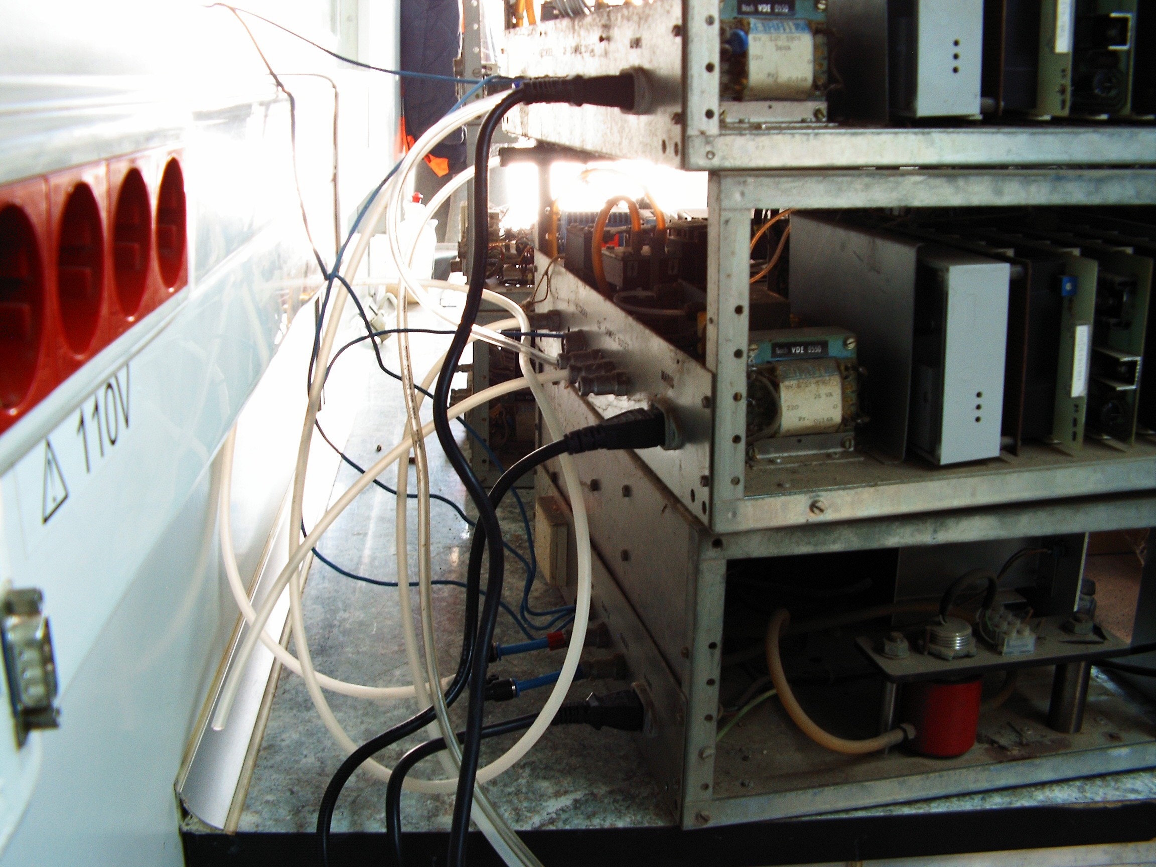
Rebuilt two PSUs on some cheap Chinese experimental PCBs. Input 220VAC, output +/-15V (small box) to power a signal amplifier instrumentation barrier (big white box in the right side). Spare parts taken from the supplies at work. I reused the original socket.
The other one inserted inside Chroma 2 - that white box mounted in the middle unit.![]()
This is the original 24V stabilizer. Art work.
![]()
Power distribution Unit which supplies 24V for pump, gas heater, DAC/ADC/instrumentation preamplifier and TCD sensor.
And the PCB back side...![]()
![]()
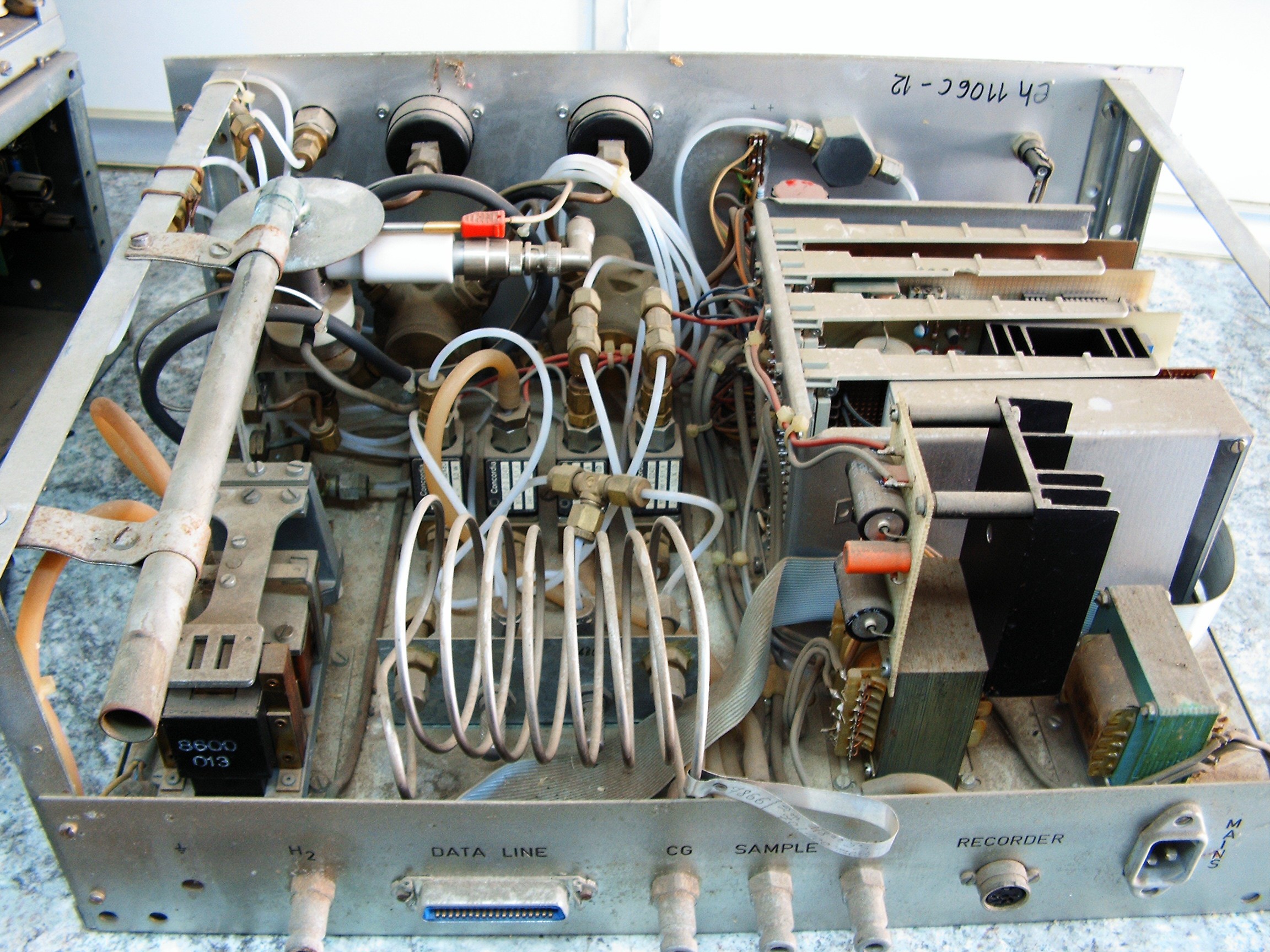
I replaced the FID sensors (flame ionization) with TCD (thermal conductivity detectors) - spares from the newer chromatographs I have at work place, so a new instrumentation preamplifier+DAC/ADC is needed. After consulting the service schematics, I came out with this beauty on a Chinese experimental PCB.
I am unable to paste those service manual pages, as I will break my confidentiality contract with the Company and boss will throw me out without any comments.
Rebuilt an analog-to-digital/digital-to-analog converter. I will later want to log everything on some normal computing unit.![]()
Board also contains three op-amp, an ADC, some open collector ICs, reed relays and of course the power stabilizer.
I also built a digital output bus for parallel port.
Notice the old-school analog to digital converter (resistors + capacitors) near the data bus on the left side.
Old school wiring insanity. Welcome back to the Madhouse. Again.![]()
![]()
Original socket reused. The original board is oxidized, filled with rats poo and it's not fit for the new sensors. Colleagues ran away - again - when I started to touch that pooed thing in order to throw it out.
![]()
Hacking inside rat poo is pure insanity. Instead, this instrumentation preamplifier DAC/ADC board should perform wonderful. Boss will also cancel my contract if any magic smoke is released, he likes what I do but he's angry I did not inform him earlier about my intentions. I need to be extremely careful.
Relay 1 (bottom) activates the pump. Relay 2 activates the heater. Black relay switches on the board. Reed Relays (4 pieces) set 4 different temperatures to the heater. Multi-turn pots adjust the sensor signal levels.
![]()
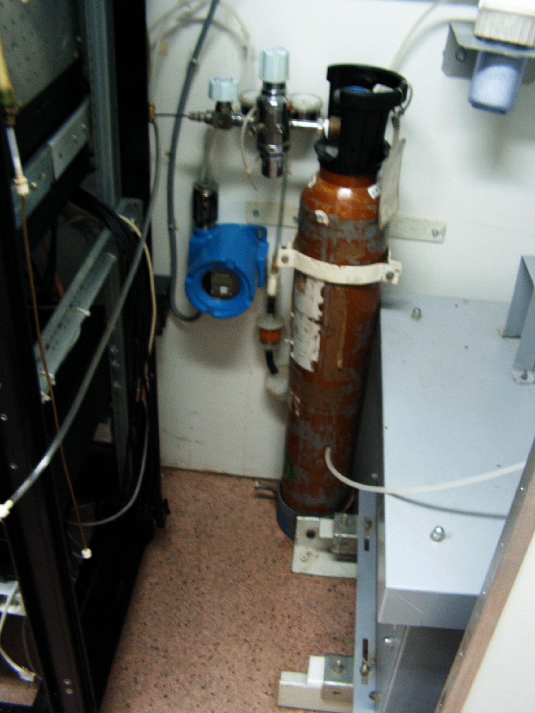
I need Helium as a carrier gas, connecting the pipe line....
![]()
Everything wired up and ready to go.
![]()
Electronic recorder repaired. Ground is common, so I need two signal lines - from Chroma 1 and Chroma 2.
![]()
110 Volts is for pussies.
In EU we have 220 Volts because blowing things gets funnier.
![]()
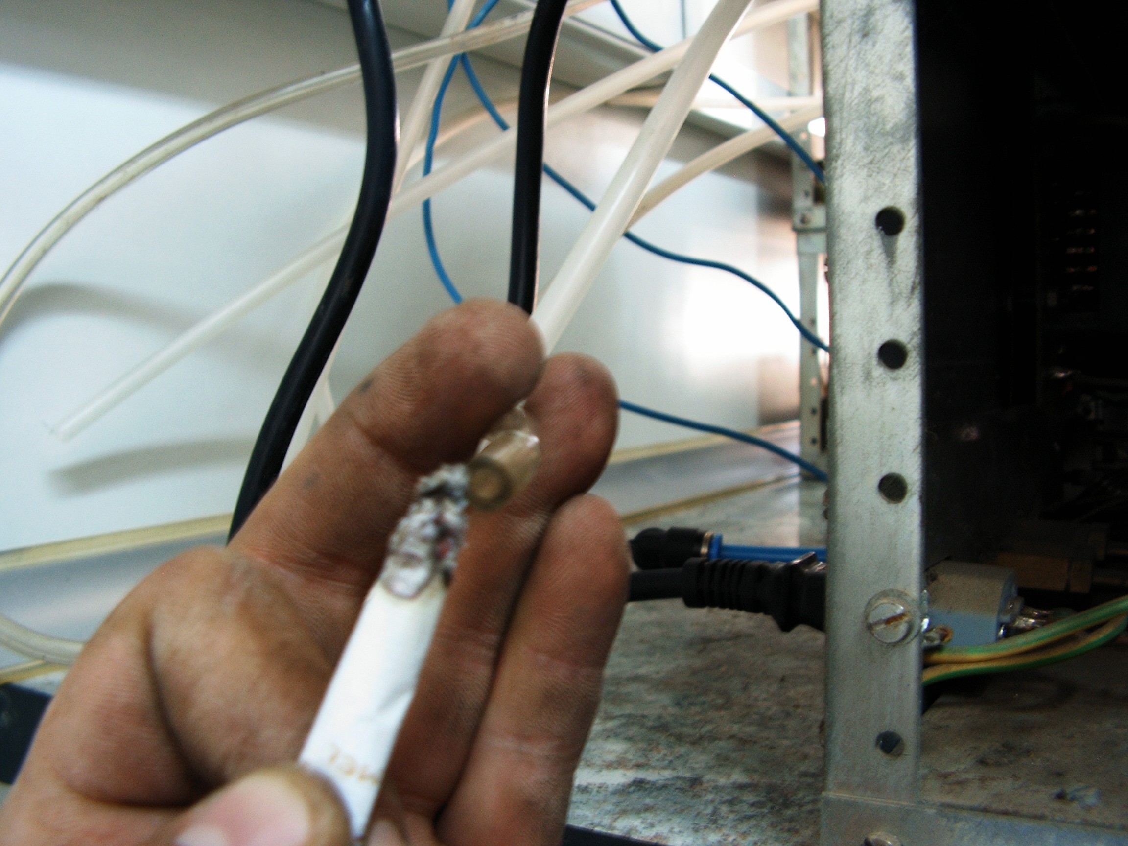
Carrier line connected. There are two pipes with free ends: transparent one is the sample gas for Chroma 2, the small pipe at the left corner is sample gas for Chroma 1. Both Chromas are connected to the two input lines of paper recorder.
No magic smoke so far.
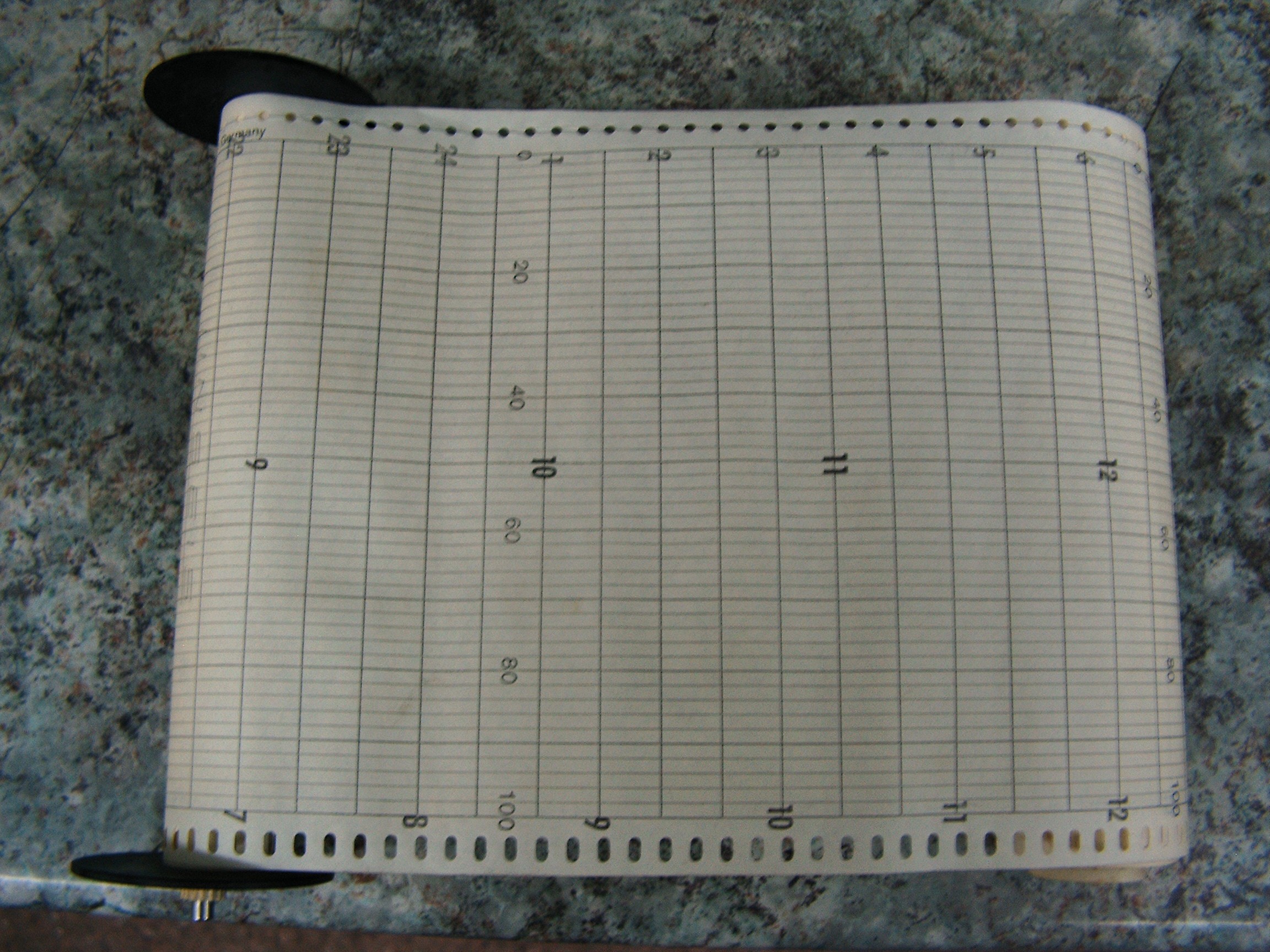
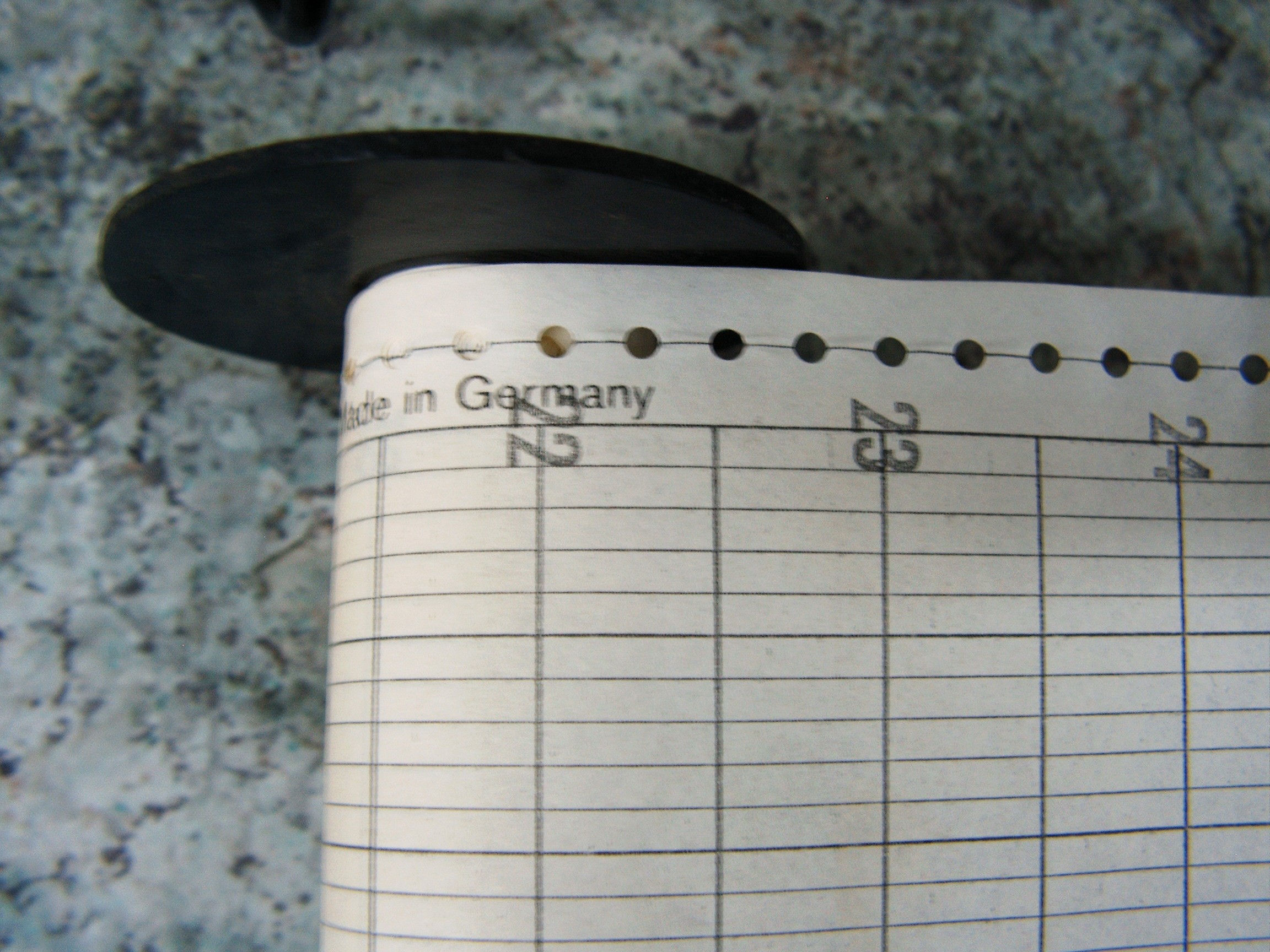
I turned the warehouse upside down until I found some spare recorder papers. Rats did not get them. This is good.
![]()
![]()
Made in Germany. Quality guaranteed.
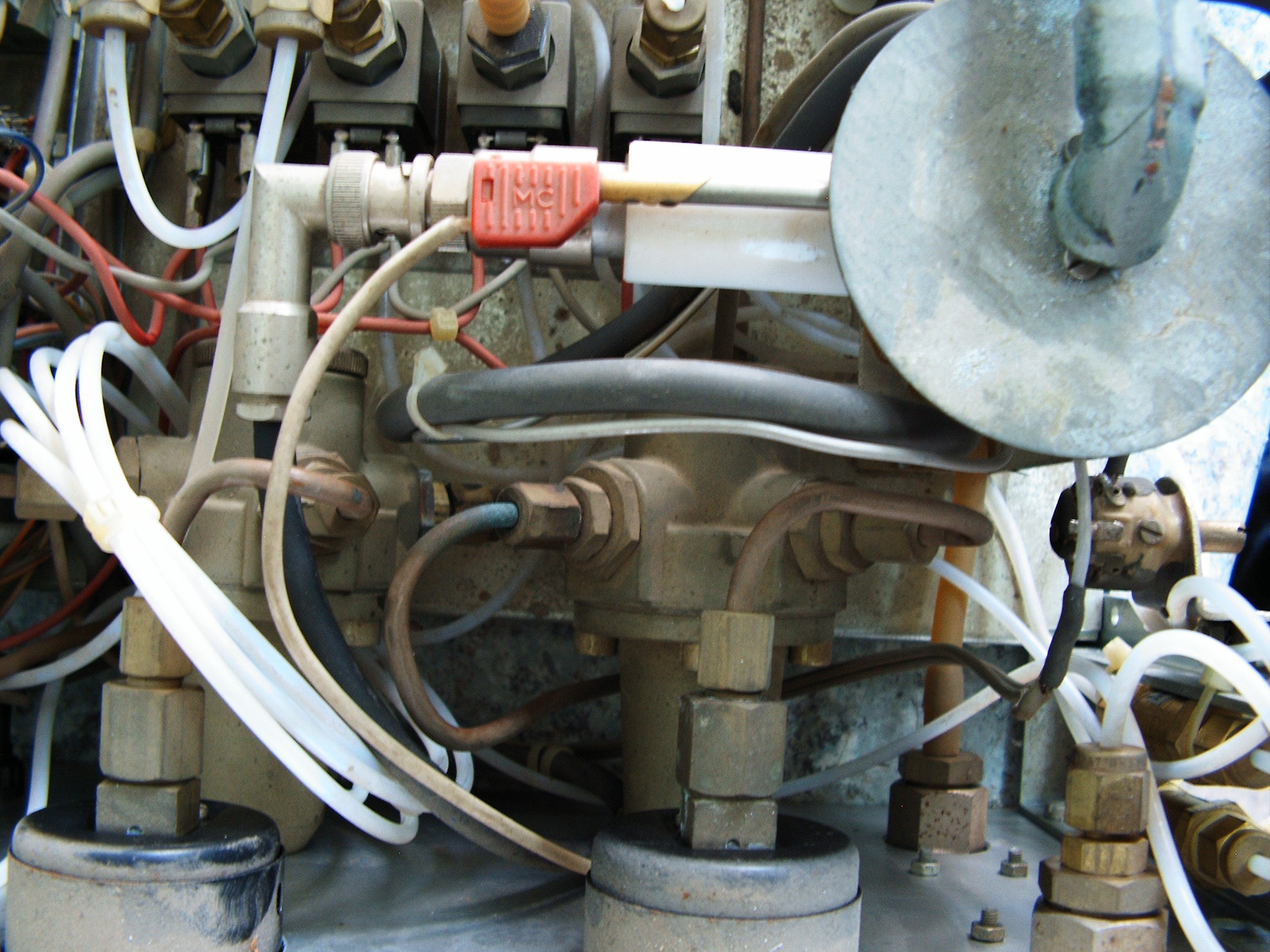
Powering up again.
Still no magic smoke from the boards. Instead it comes out from the heater and from the red temperature sensor labeled "MC".
![]()
No lights are present on the panels and the silence is very suspect.
![]()
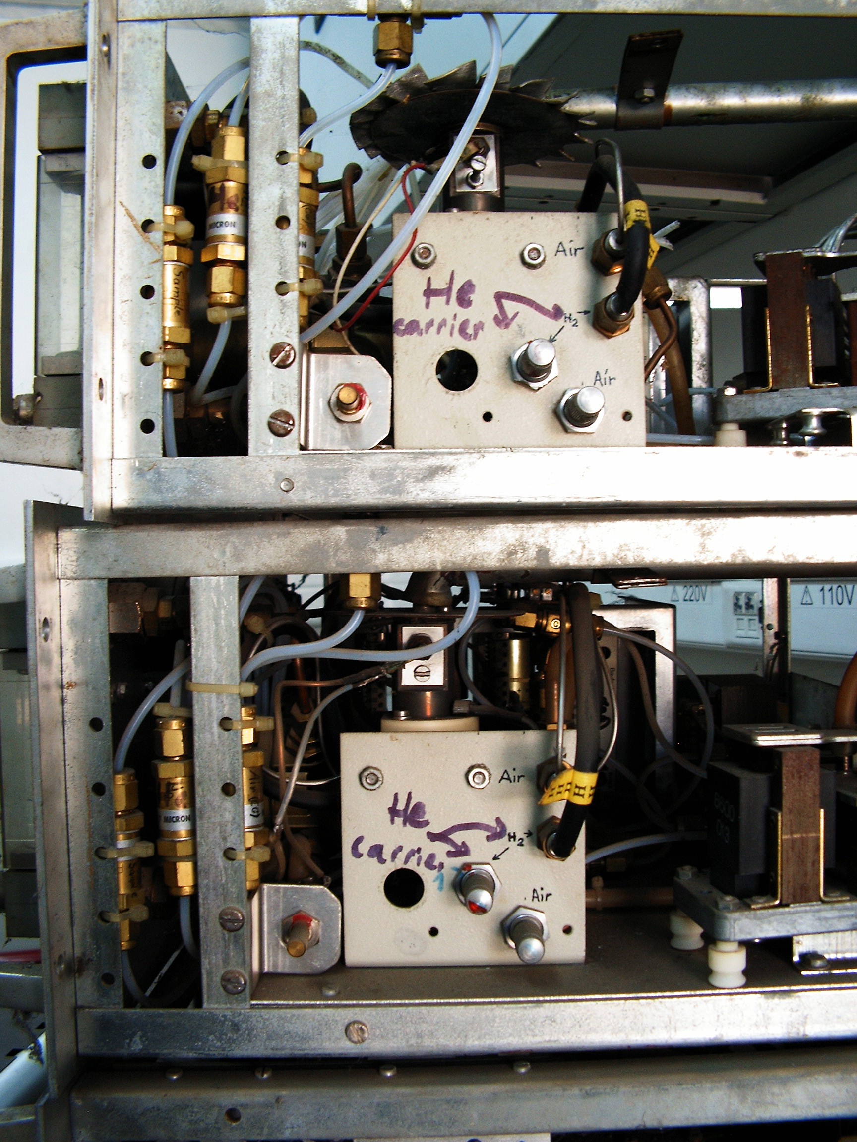
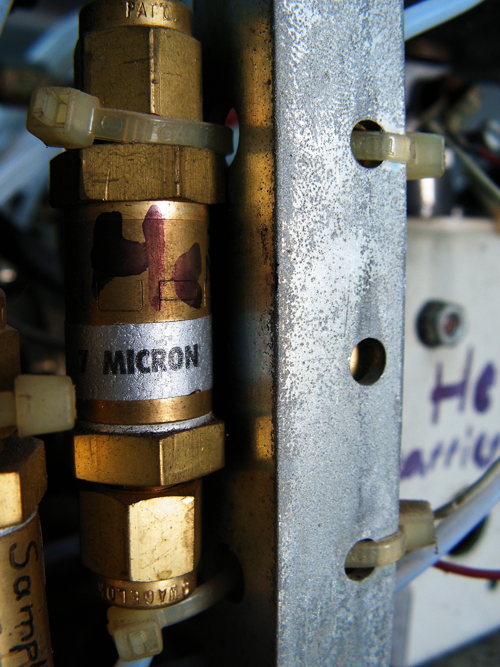
Initially these Chromas were designed to use Hydrogen as a carrier gas due to the specifics of the FID sensors. We're closer to the 21st century due to the new TCD sensors and now I have Helium, which is a stable gas and it's not starting fires. And it gives people funny voices when inhaled. Air and Carrier Gas (helium) flows adjusted for both Chromas. Flame generator removed. I don't want to risk burning things. Air flow also closed. There's no need for air. Nothing burns, so no air.
![]()
Helium is injected through a 7 micron hole in the mixture chamber, which is heated and receives the sample gas from the column.
After one minute, pumps started to work with big noise. Again, all the colleagues jumped from their chairs and ran out scared. Someone wants to call the emergency number and ask for the nearby asylum. [skaarj] is suspiciously calm, he built strange devices all day long, no smoke came out so far and apparently he really enjoys messing up with stinking rats shit&piss.
One more minute, the system starts huffing and puffing, electronic recorder starts to spin slowly and.....
![]()
SUCCESS!
We've got our carrier gas recorded!!!!!!!!!!!!!!!!!!!!!!!!!!!!!!!!!!!!!!!!!!!
Need to refill the pencil, someone brought me some ink from a printer refill kit.
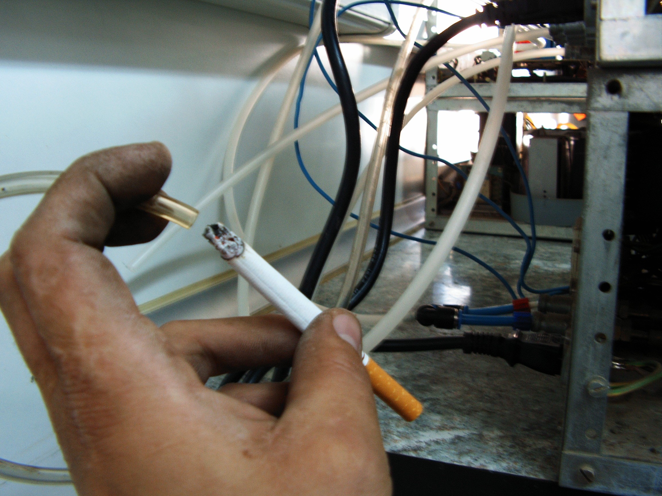
Now, need some sample gas. Nobody is willing to fart in the hoses, so I need some magic approach....
![]()
Pumps suck in some magic smoke from a highly toxic source.
![]()
And we have some reading. Need to grease all the mechanics inside the recorder.
Sample gas input, one more time...
![]()
One more minute, huffing, puffing...
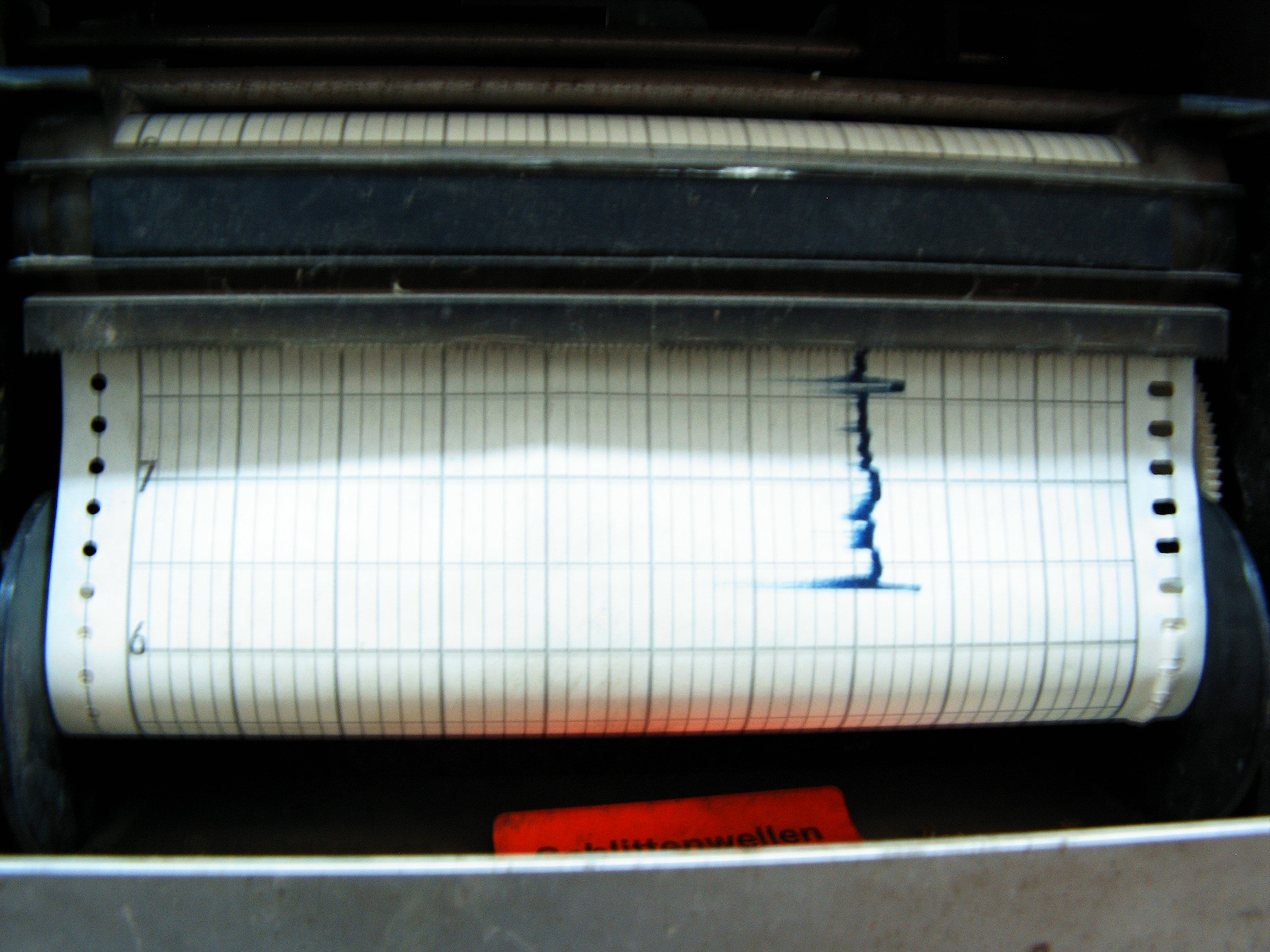
![]()
And we've got ourselves a spike!
![]()
![]()
![]()
Red label says something in German - "clean with alcohol only".
![]()
![]()
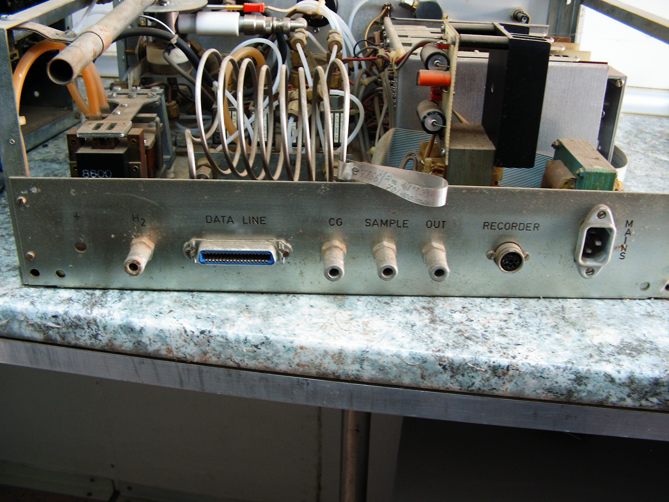
Allright, explaining one more time how this works...
![]()
H2 input - carrier gas input, I used Helium;
Data line - I want to log everything to some PC using parallel port as an input;
- Sample gas goes through both CG and Sample hose connectors;
- OUT hose connector releases the gases after they pass through the Chroma;
- Recorder DIN5 connector - output analog data, it passes the electric analog signal to the recorder;
- MAINS: 220V input without any magic smoke;
- FID sensors are replaced with TCD so no need to burn any hydrogen;
- power supplies and ADC/DAC converter rebuilt.
Allright, so we've got a working 40-years old, rat-pooed chromatograph which would make all Hackaday staff, editors and jury scratch their heads. We've got some readings from a highly toxic magic smoke source.
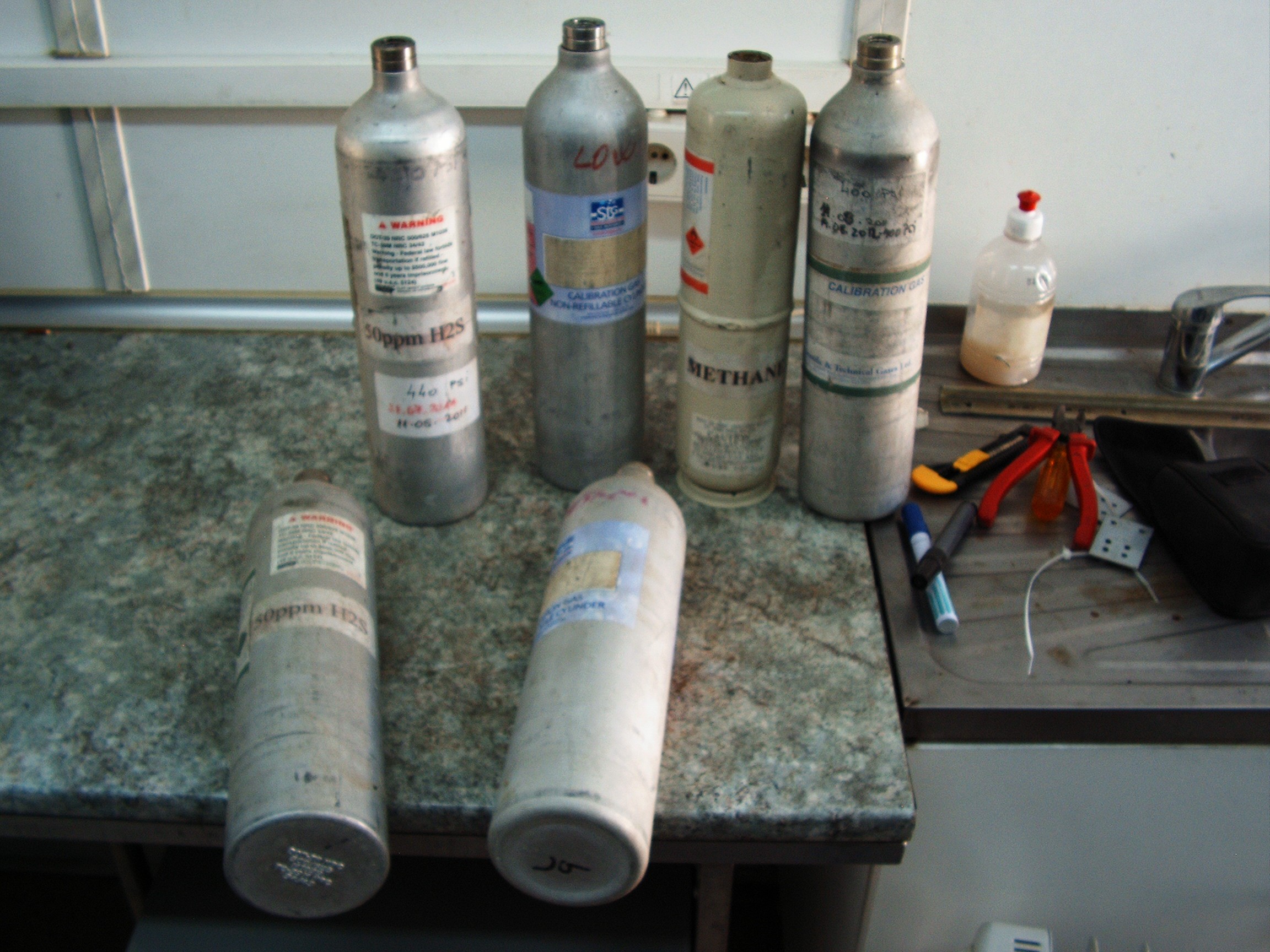
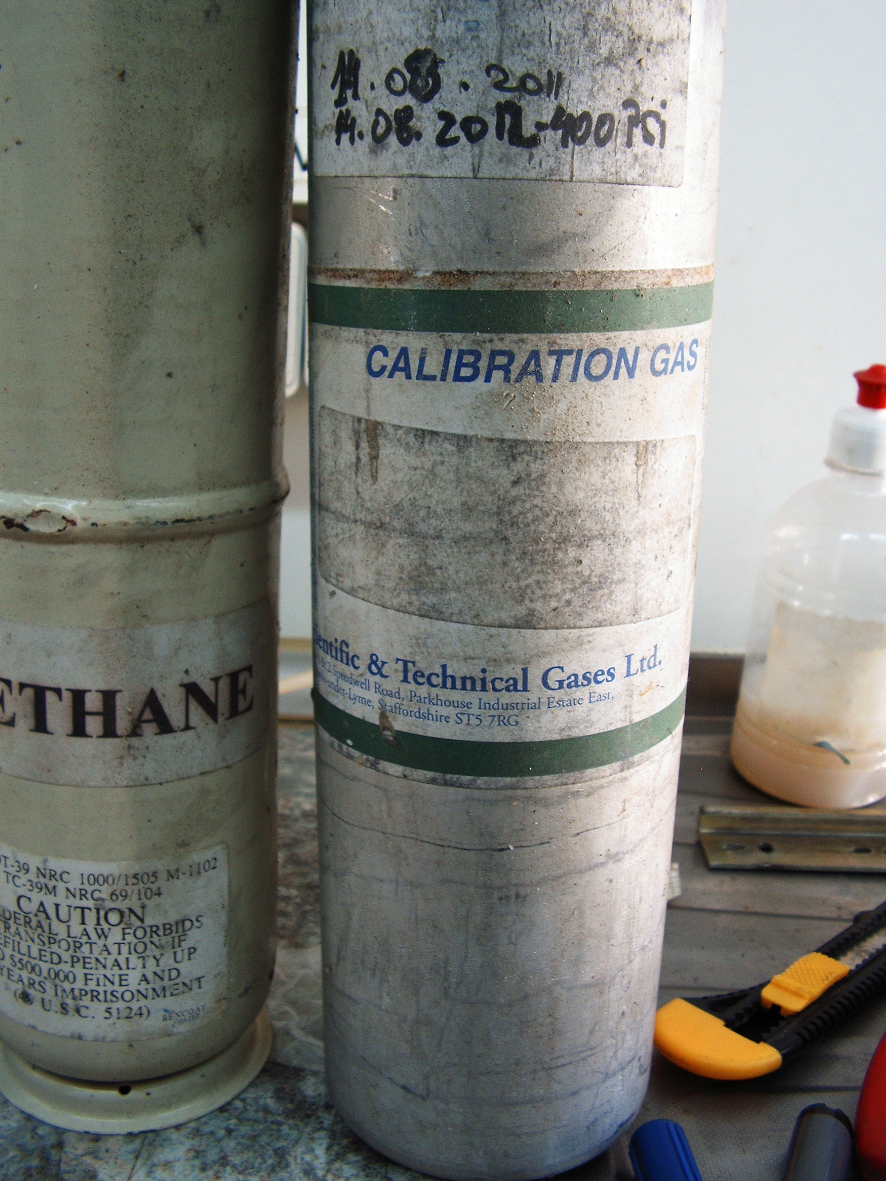
The next step is to record all the spikes coming out from these calibration sample gases:
![]()
H2S, Carbon Monoxide, Carbon Dioxide, Methane, low-end (2%) hydrocarbons...
![]()
And some nitrogen compound I am unable to identify properly .
I need to record each of them and see at what time the corresponding spike is recorded. Then I need to record all of them mixed and the Chromas should output the spikes in some order, depending on how heavy the compounds are.
Lighter gases should come out earlier and heavier gases should come out later.
At this time the stage is prepared for recording the exhaust gases (chroma out) and input mixture gases (gasoline, air, later added hydrogen-oxygen mixture) and compare the resulting charts - for these two cases:
1. The automobile engine runs normally on gasoline;
2. Engine runs with injected hydrogen-oxygen mixture (releases from electrolysis) through the air intake manifold.
The output charts results are compared with the calibration gases charts and see what kind of gases are recorded - where (meaning "at what time") the resulting spikes are placed comparing to the reference (calibration gases) spikes.
Still no magic smoke so far....
[END OF TRANSMISSION]
______________________________________
kernel panic: improbability coefficient below zero
Retro-futuristic automobile control panel
Conversion of dashboard from an old, Communist clone of the French Renault 12 (Dacia 1310)
 Siemens re-branded StorageTek Industrial (PERTEC) interface tape drive
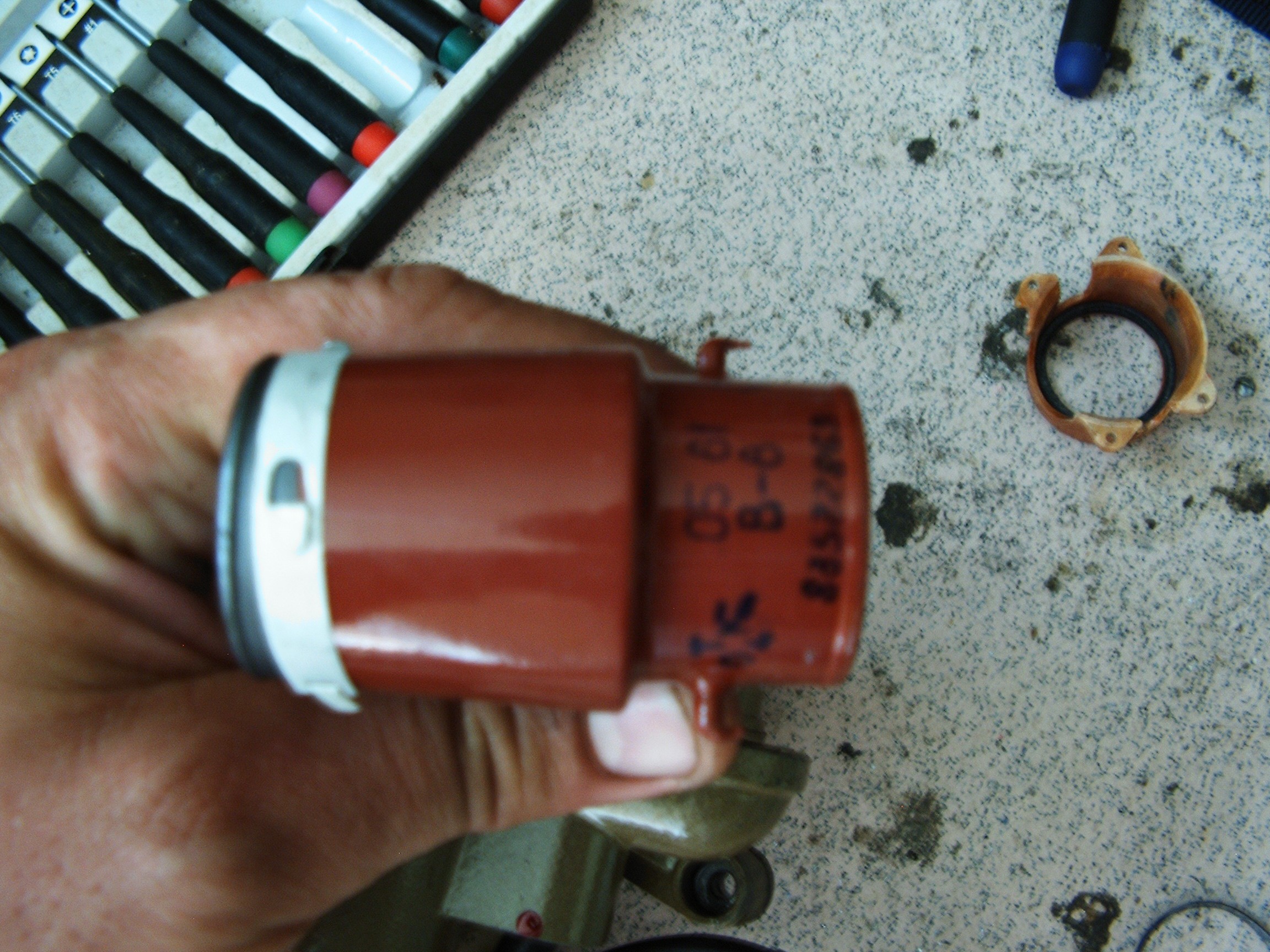
 Connected here: pin3 = 3.3V, pin5 = VibraIn, pin8 = GND.
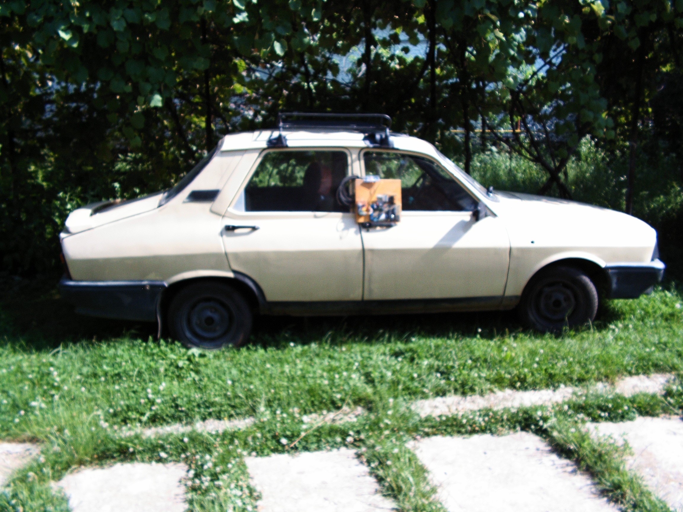
 Accelerometer knocked with a knife:
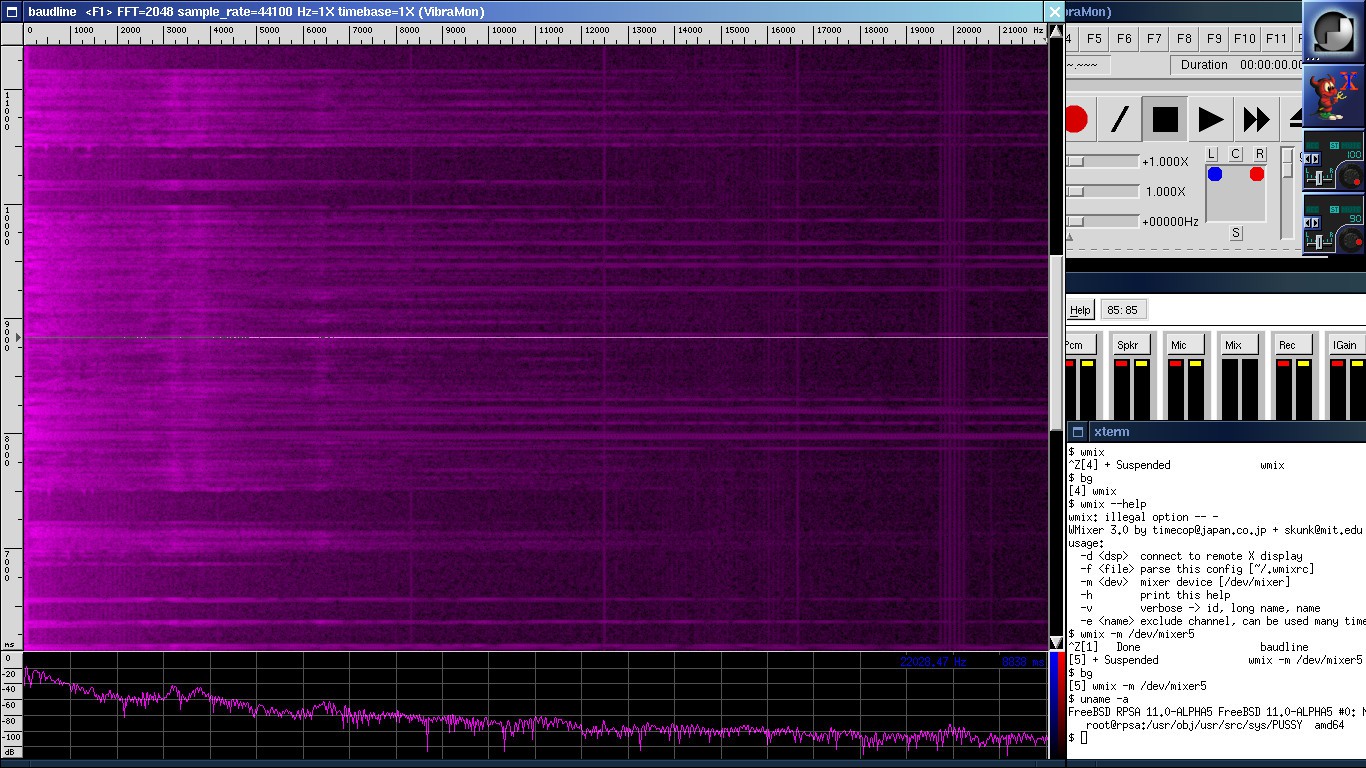
 That's it. Here we go.
 System powered up and warming. Paper graphic recorded loaded.
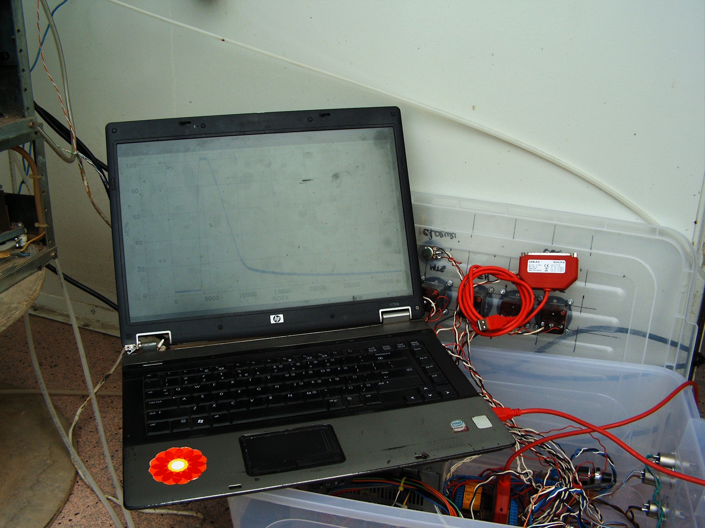


