 [skaarj]
-
Citizen scientist: first failure - getting access to high performance equipment
06/06/2016 at 23:16 • 0 commentsCongratulations for the winning colleagues.
May the prizes help you cover all your bills and push your hard work forward.
So updates: Unfortunately I am forced to drop the pollution reduction project for Citizen Scientist round.
Somehow the faith shaped my path that starting from this moment, I am no longer able to rent the access to the required equipment in order to perform the automobile exhaust gases analysis in a scientific way.
This is again becoming true: "there is no way another small victory from that place will ever be allowed."
In other words, I will no longer be successful in getting access to the following equipment:
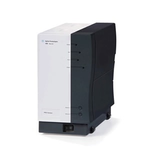
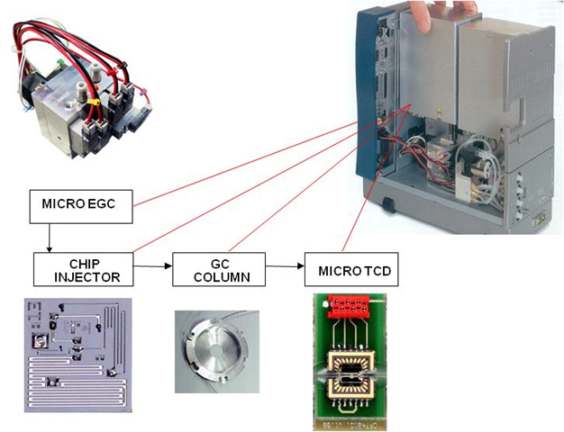
- 1 x MTI M200 Gas Chromatograph:
![]()
![]()
![]()
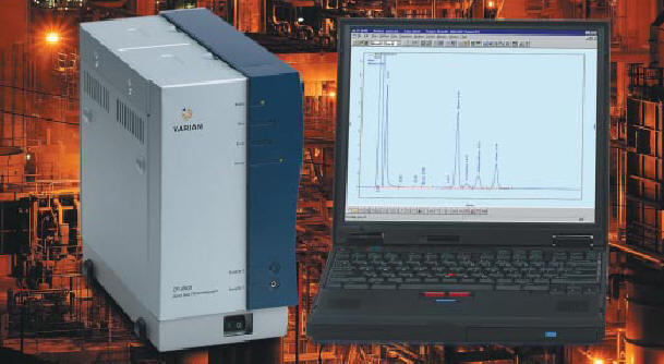
- 1 x Agilent Gas Chromatograph:
![]()
![]()
![]()
- 1 x Total Hydrocarbons Gas Detector
![]()
![]()
- Carrier and Calibration Gases: Helium (carrier gas for chromatographs), Carbon Monoxide, Carbon Dioxide, hydrogen sulphide, various nitrate-based and hydrocarbon-based gases;
![]()
- 1 x ANAX-500 Well Drilling Site Mud Logging Server - in order to perform the required calculations and graph everything into professional charts using industry-certified equipment.
![]()
![]()
This picture shows the interior of a Well Site Mud Logging Cabin which performs - among other functions - the gas analysis. From top to bottom: Anax-500 server, Agilent Gas Cromatograph, Depth controller, Total Gas Detector and backup Total Gas Detector.
Citizen Scientist will probably be covered with vibration processing only.
Probably.
I have a promise for access to an ancient, 40 years old Chromatography Station which is heavy and fits inside a truck. That's what I could get so far. And I will have to fix it first. So back to trash dump.
Later edit [at round finish]: the work for Citizen Scientist round was not acknowledged. Not as published blog article, not as a win acknowledgement. Just as predicted on the title.
No further comments.
______________________________________
kernel panic: improbability coefficient below zero
-
Can-Bus Redux (II) - Software
05/30/2016 at 02:03 • 2 commentsAllright.
We have an Arduino, a tiny cute terminal, the RasPI, some wireless gasoline level sensors and finally some other sensors interfaced with the ex-insane electrical installation.
Server side (raspi) connects to the Arduino via serial port and reads a bunch of data which is later processed and displayed on the screen.
The WITS-style data is processed such as on each column, only that measurement category will be displayed.
An automobile diagram will be displayed on the screen. For now just in console mode, there is no way I can install anything graphic soon. FreeBSD is very avaricious regarding packages for newer core architectures. No image viewer - so no display support for HaD logo yet.
Server side software is based on picocom v1.4 serial port manipulation program.
Arduino software is entirely original.
There may be some comments written in Romanian. For whoever knows Spanish and a little Latin, there are no problems in understanding.
The code is uploaded to the Files section.To compile, just issue "gmake" after decompressing. For Linux - replace the port name entry (/dev/...). The arduino sketch is also in that archive.
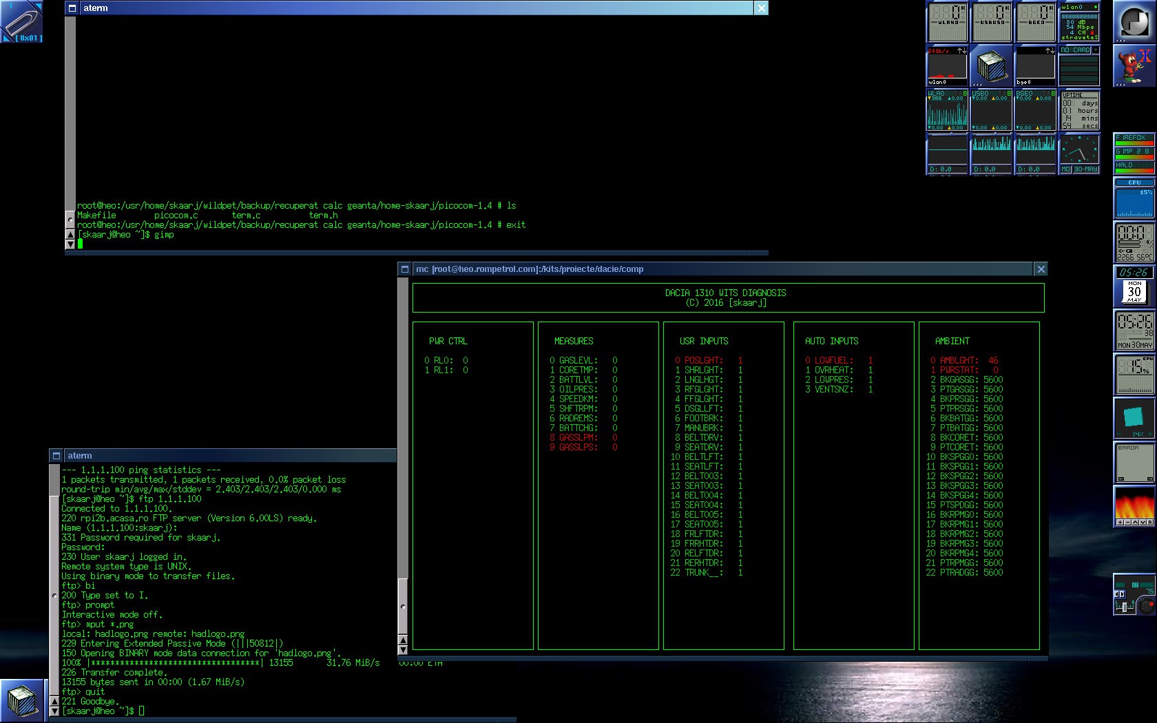
In the mean time I'm trying to capture screen on a platform without that possibility....
![]()
Screenshot with CANBUS/WITS diagnosis screen.
Operating System: Unix FreeBSD 11.0-ALPHA (RasPi side) and Unix FreeBSD 9.0/amd64 (laptop side, where I took the screenshot. No Linux. I work in petroleum industry at well drilling sites and there we use only BSD systems for industrial automation and control. Those monsters need to work without any BSOD or kernel panics due to dust, flies, mud or hot days in the Sahara Desert. No funny jokes such as Linux or M*******t are allowed, so I am sorry if I disappoint you people - from the industrial automation point of view I do not trust any kind of Linux. However the software should compile on Linux without any error.
At this time just ambient lights data is coming because the unit is now inside the house - to get a proper screenshot using a normal computer.
Some hints about the next log - Artifficial Intelligence at work - acquiring training data using flat tires and damaged bearings. So I need to buy damaged hardware, install it, and pay some dude to assist me in order to do the following operations:
- install bad bearings;
- install bad bushings, malfunctioned pivots;
- install worn axles and worn steering rods;
- build some device in order to flat the tire while driving
All of these to record the precious training data.
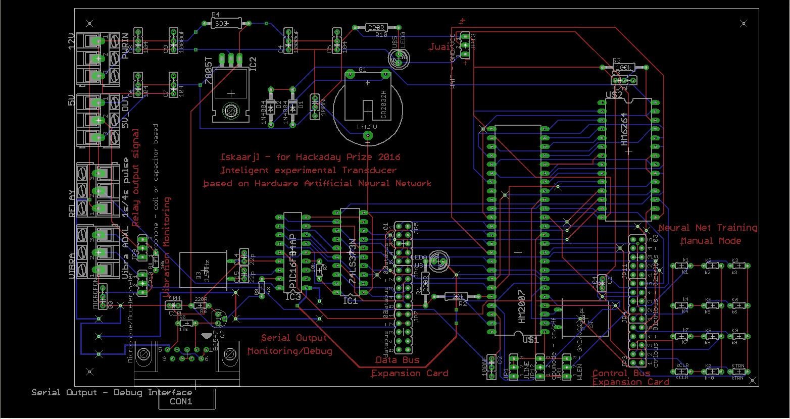
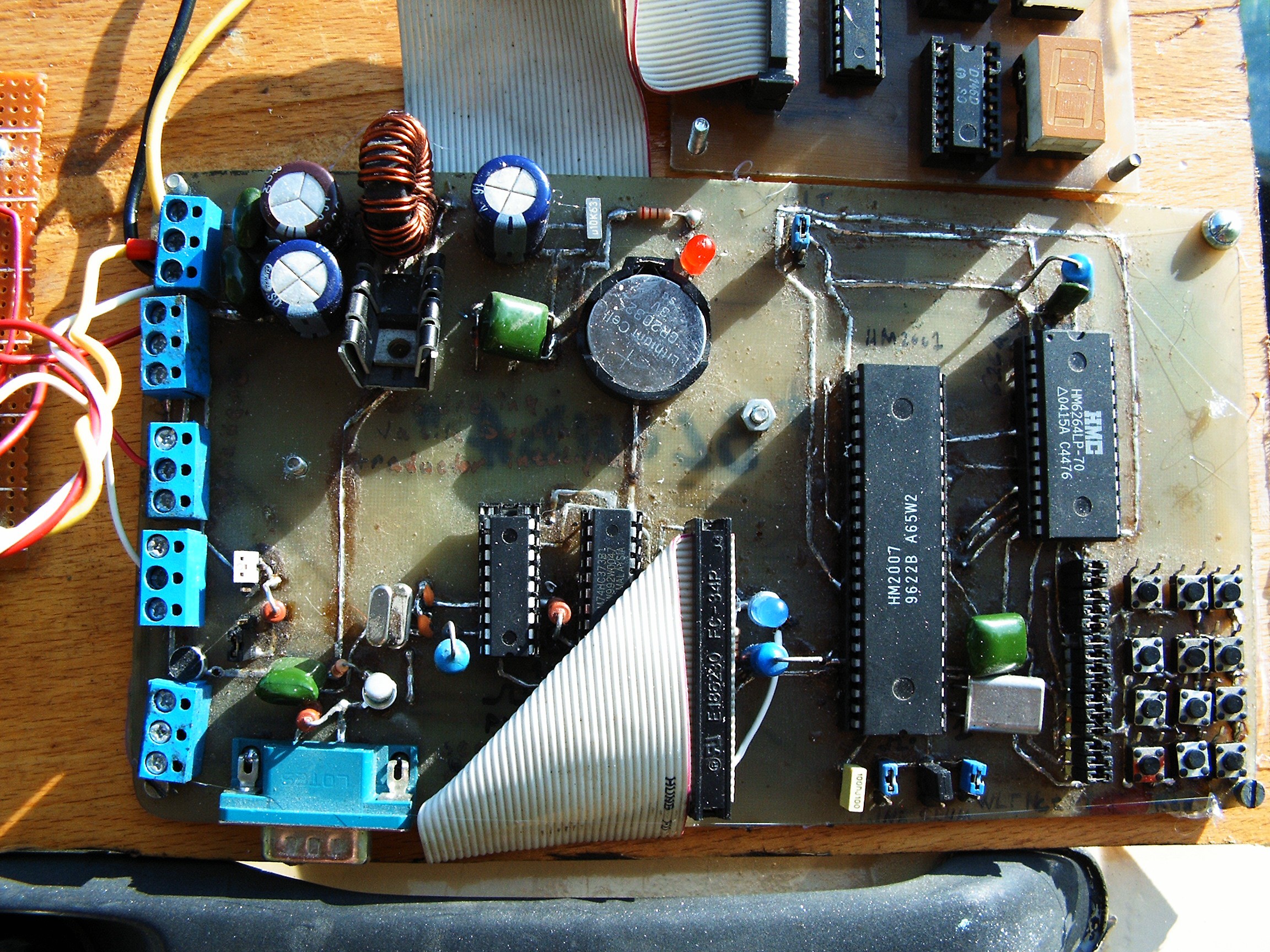
The experiment will test the capabilities of the my Artifficial Neural Network-based mechanical faults diagnosis project I covered in one of the early logs, to see how well it performs in recognizing such bad situations. That one needs to be rebuilt too because the motherboard was made by hand.
At this time the stage is almost ready for Citizen Scientist round - when I start experiments I need the equipments to be installed and in working states.
The next log will probably come in around 2....3 weeks.
[END OF TRANSMISSION]
______________________________________
kernel panic: improbability coefficient below zero
-
Rebuilding gauges and dials
05/30/2016 at 00:49 • 0 commentsThis was done at the beginning, but until now I had no chance to write a log about this.
So why do I want to mess with the dials? Simple, because the original dials look sad. They show nothing I can use to understand about the engine.
The desired functions are as following:
- back light for the gauge pointers (needles);
- back light for the gauge dials;
- each light is adjusted independently;
- two extra gauges added;
- all gauges (except speed and RPM) are controlled from the Arduino;
- light (leds) and gauges are controlled through two Adafruit PWM controllers;
- Arduino encodes all these parameters according to the protocol I designed and built - based on some Petroleum Industry Data Transfer Standard called WITS - and sends them to the Raspberry Pi embedded inside the terminal.
So let's start:
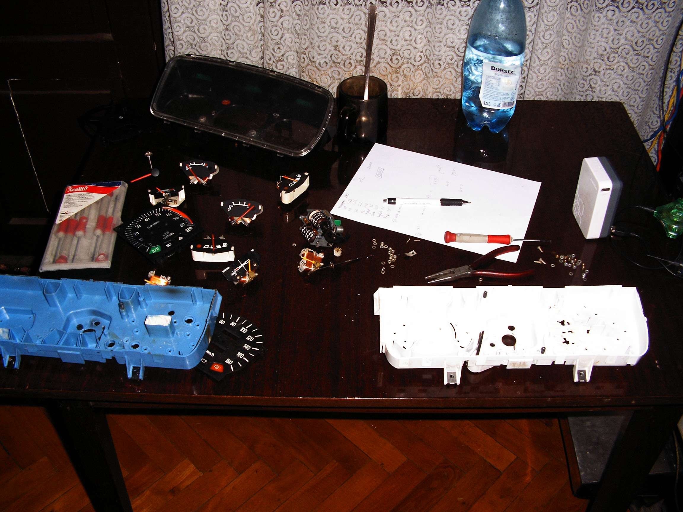
GAUGES!!! a lot of gauges!
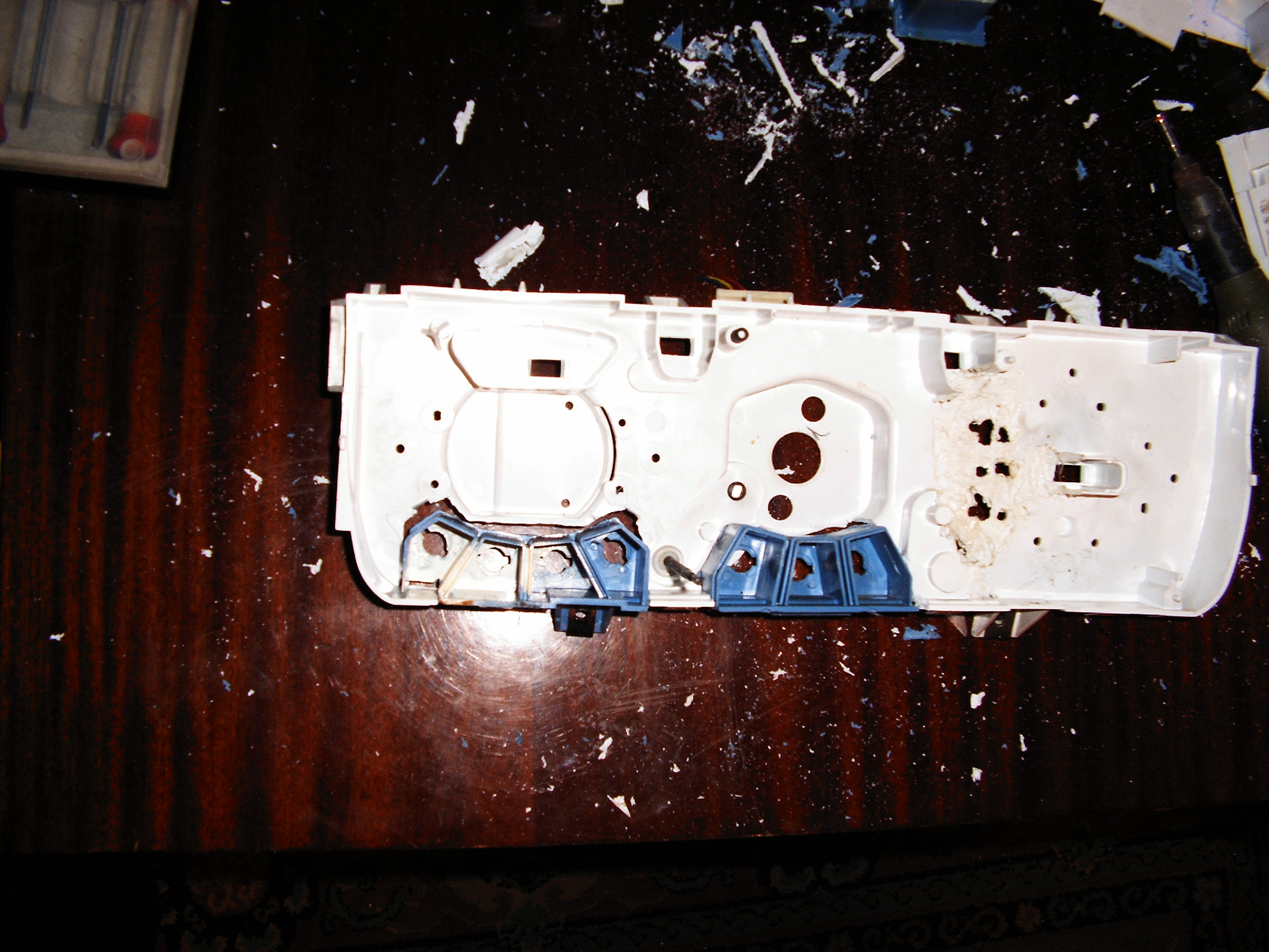
![]() Left side: the old version casing with more warning lights than the newer version. Last version had only two gauges - gasoline and speed. I need the precision of the last version dials but I want to know as much information as possible about the engine.
Left side: the old version casing with more warning lights than the newer version. Last version had only two gauges - gasoline and speed. I need the precision of the last version dials but I want to know as much information as possible about the engine.Also, the last version speed gauge has a different "daily distance reset" which does not fit on the old casing. So switching to new casing and adapting the best methods.
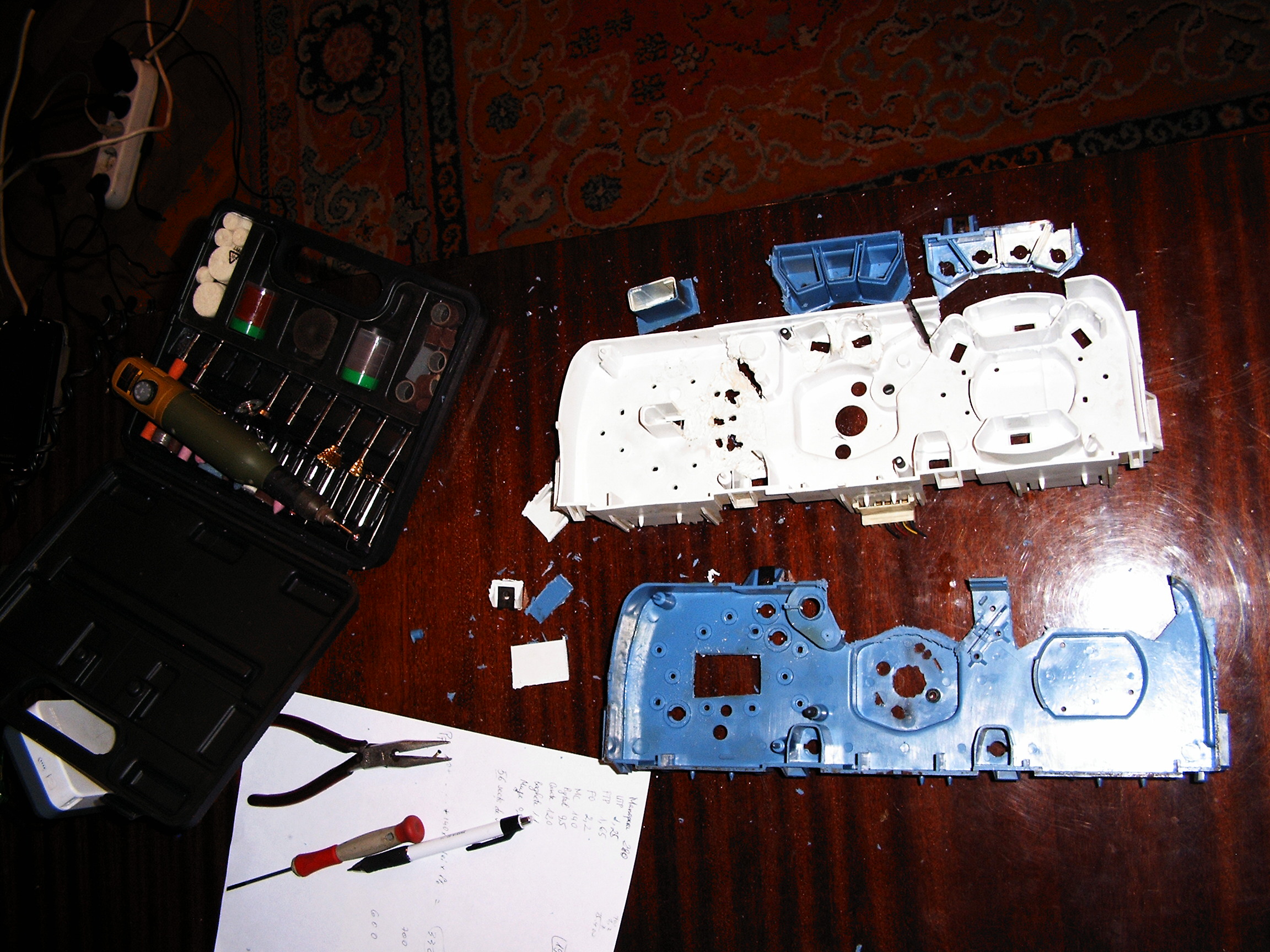
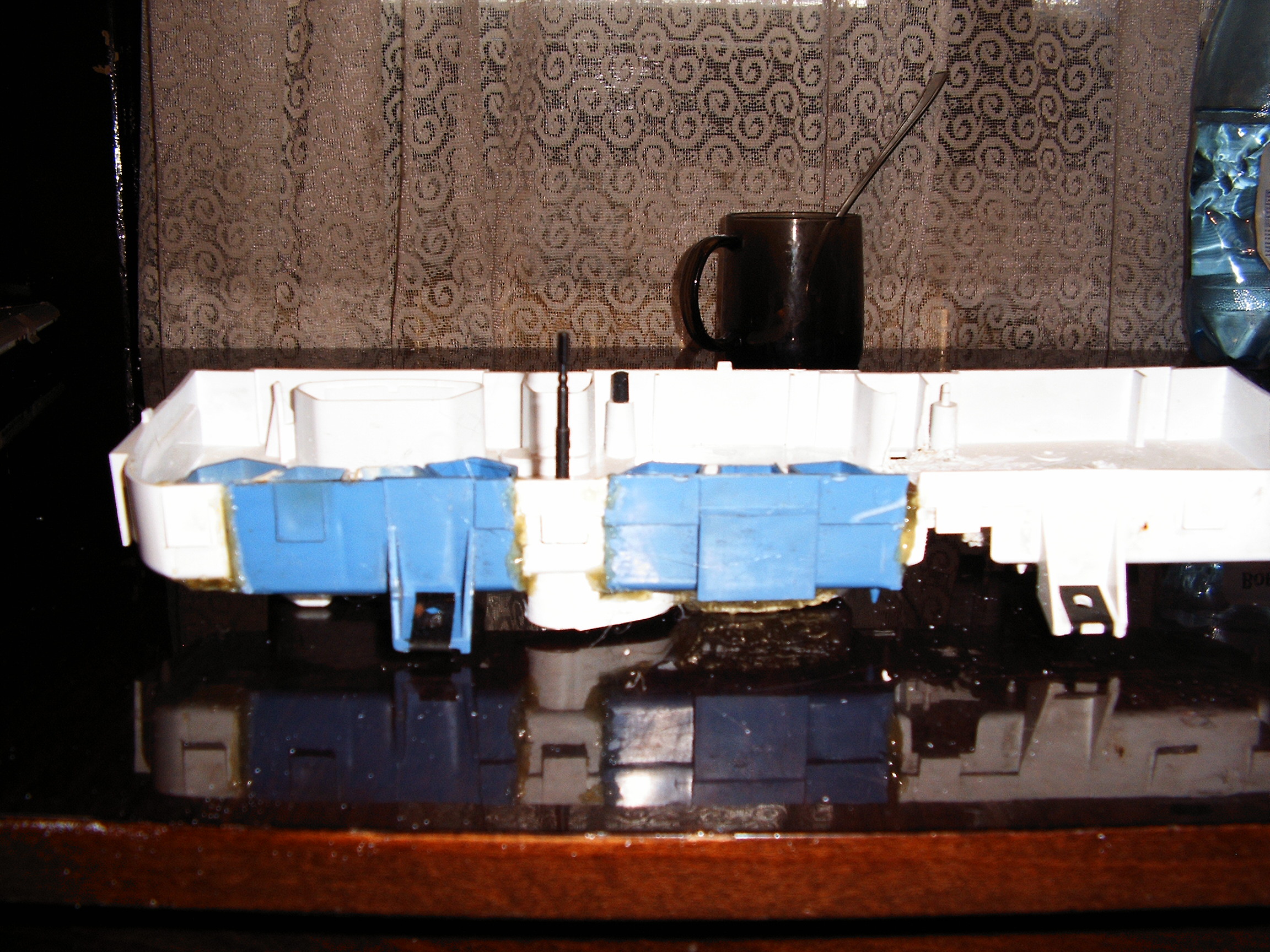
So I have to cut the warning lights enclosures and stick them on the newer version casing.
![]()
![]()
![]()
![]()
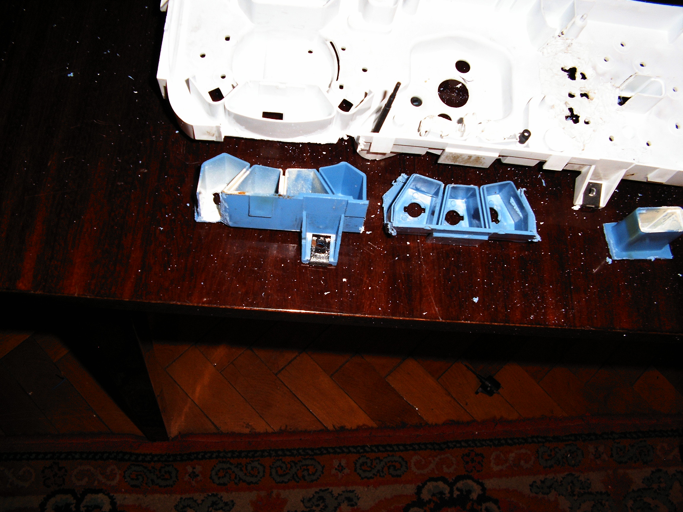
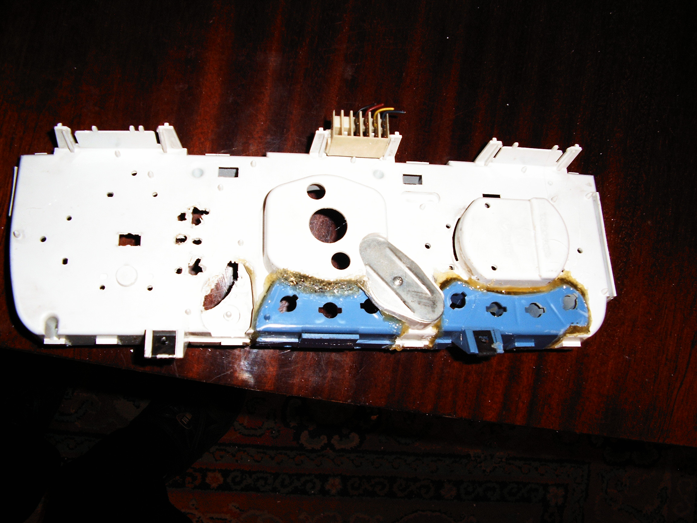
Finally they are cut together, now let's "fuse" them using melted plastic:![]()
![]()
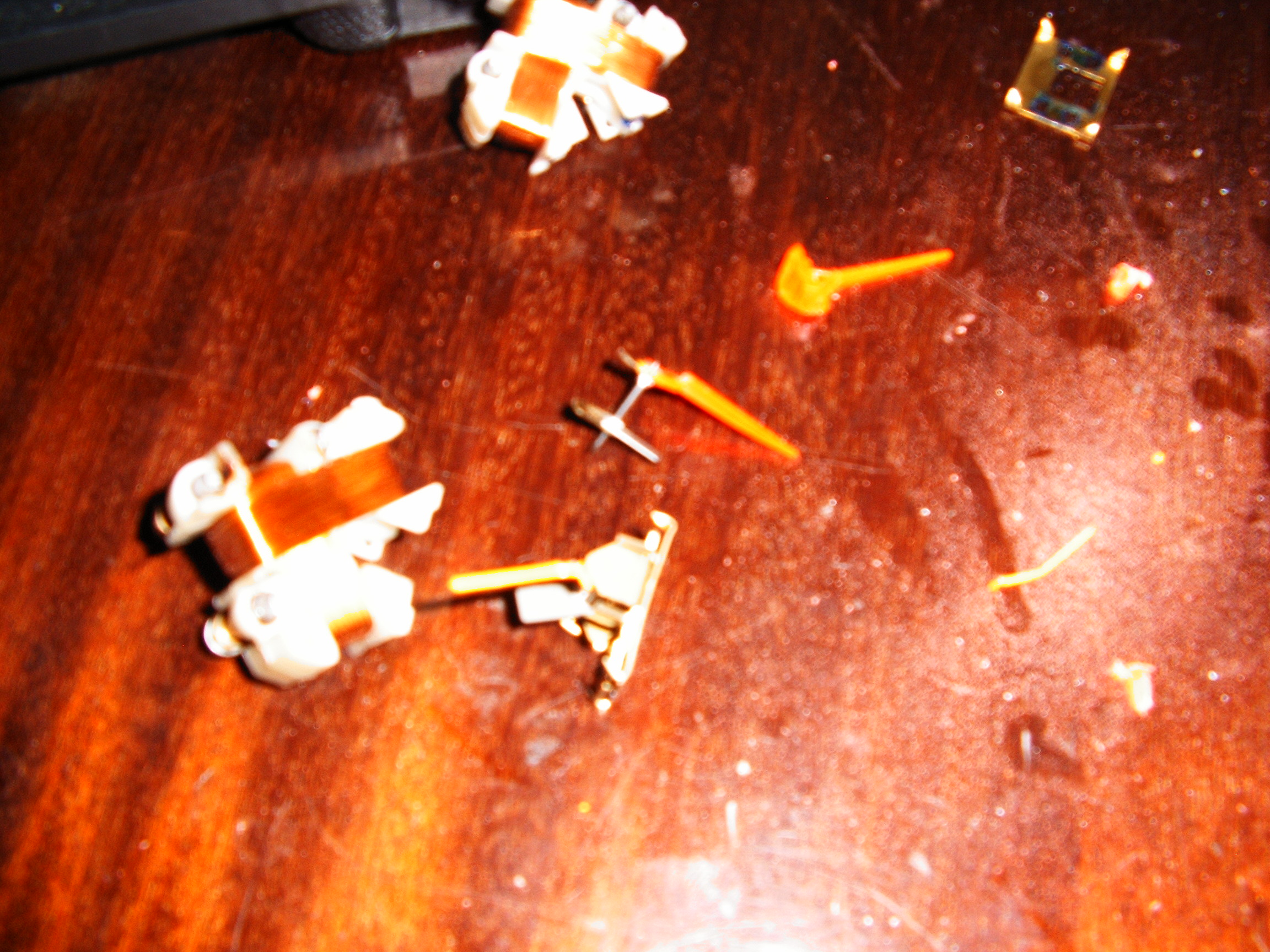
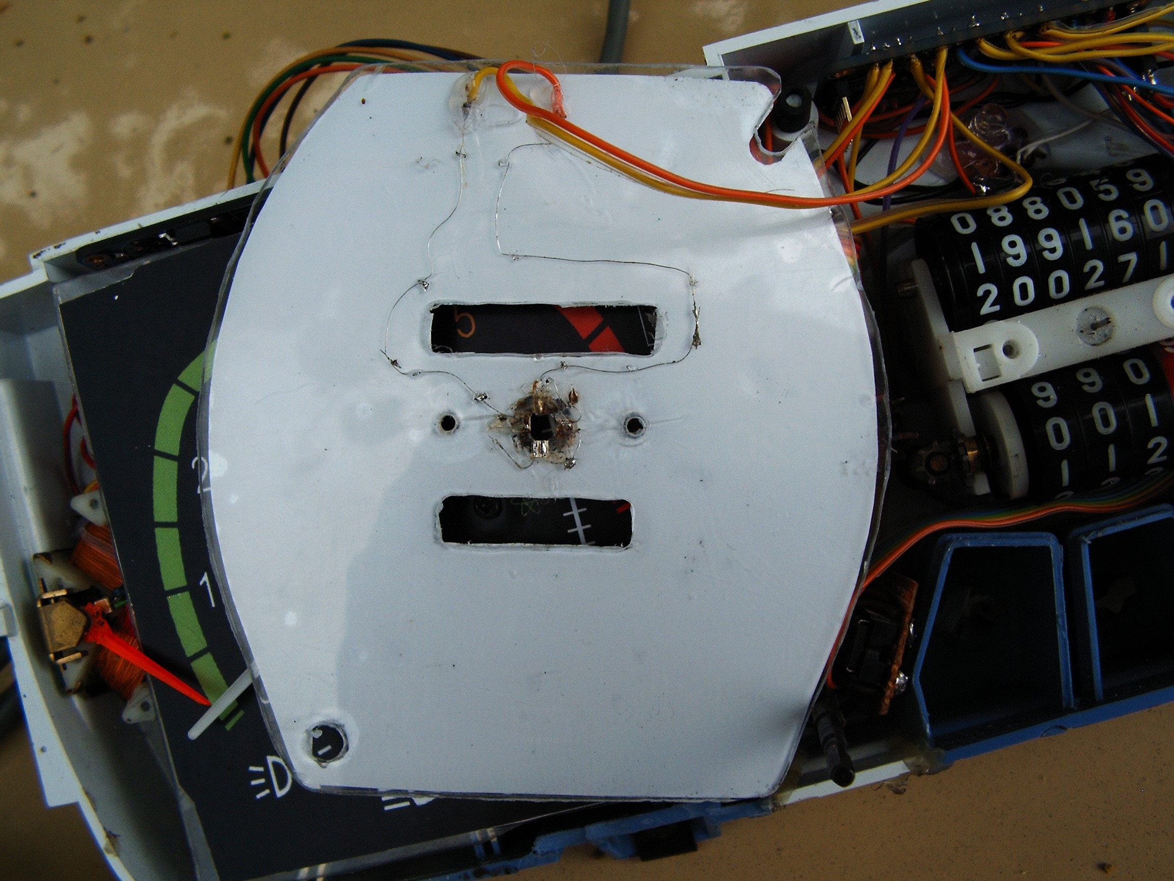
Dials pointers.
Camera has focusing problems.....
![]()
Transparent plastic needles recovered from some vehicle recycling center.![]() The aluminum pointers were removed and the new pointers were fixed using Super Glue and a lot of patience. Adjusting weights for was done for each of the 6 small gauges.
The aluminum pointers were removed and the new pointers were fixed using Super Glue and a lot of patience. Adjusting weights for was done for each of the 6 small gauges.![]()
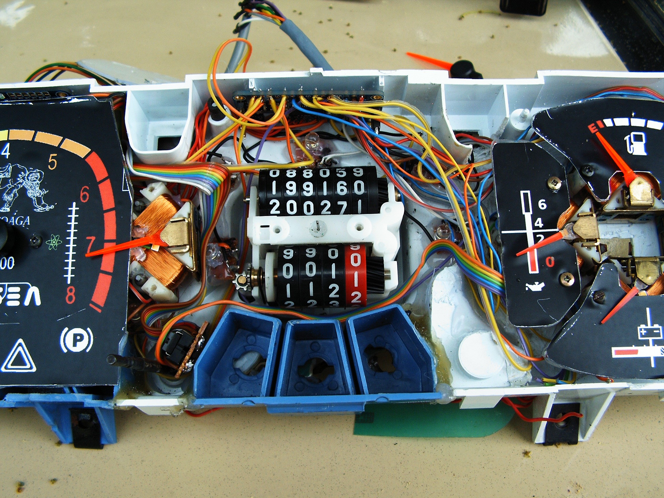
![]() Adjusting the balance was performed with the dremel tool by cuting small pieces of plastic from the pointer.
Adjusting the balance was performed with the dremel tool by cuting small pieces of plastic from the pointer.Installed instruments - back side view
![]()
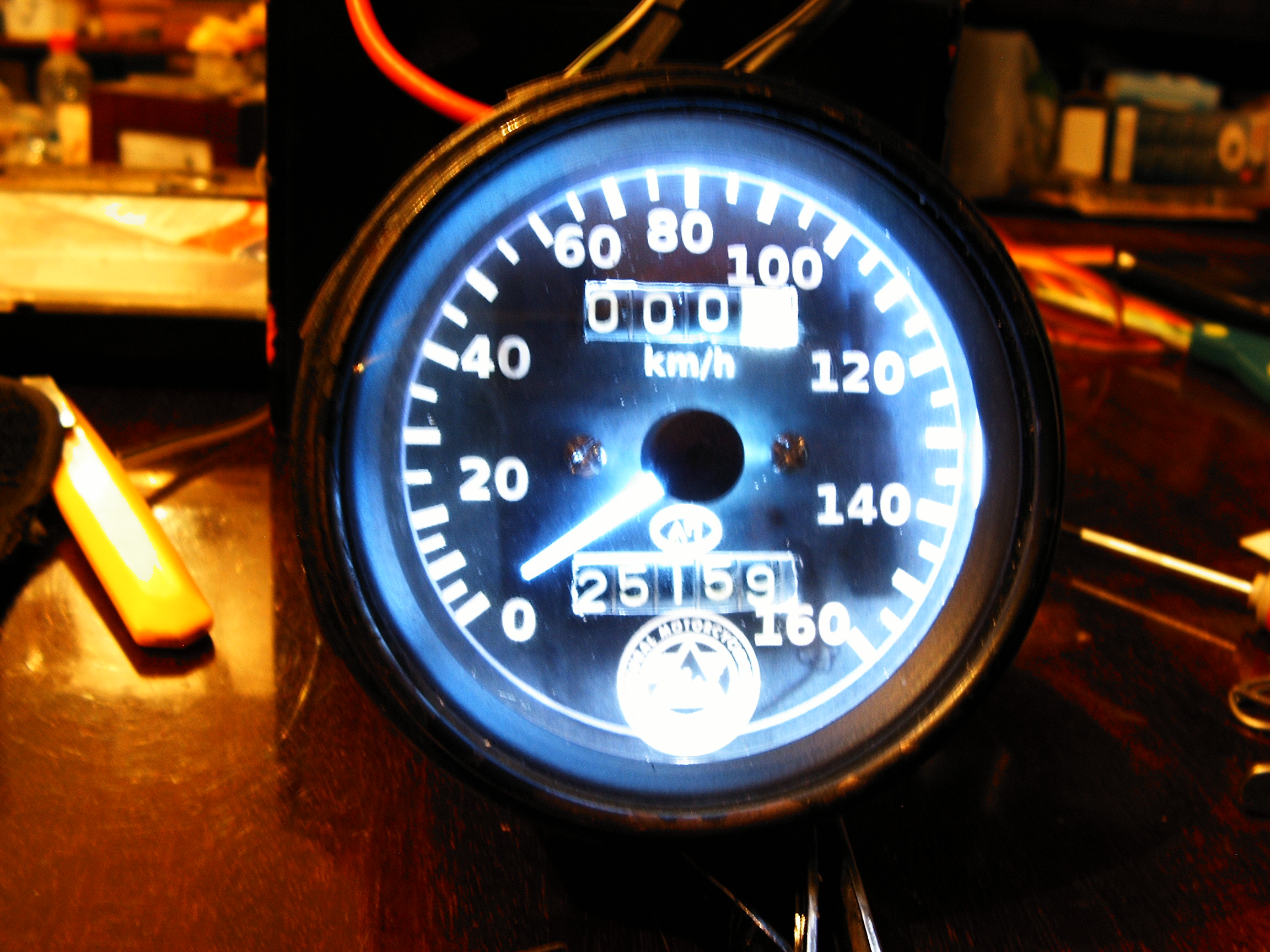
This is how it should look like - this is a gauge modification I made for my motorcycle:![]()
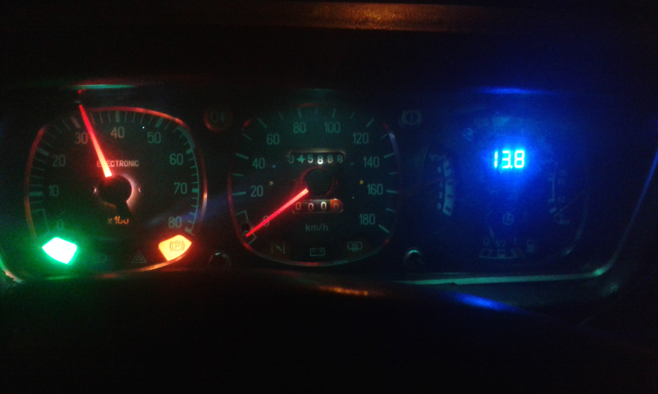
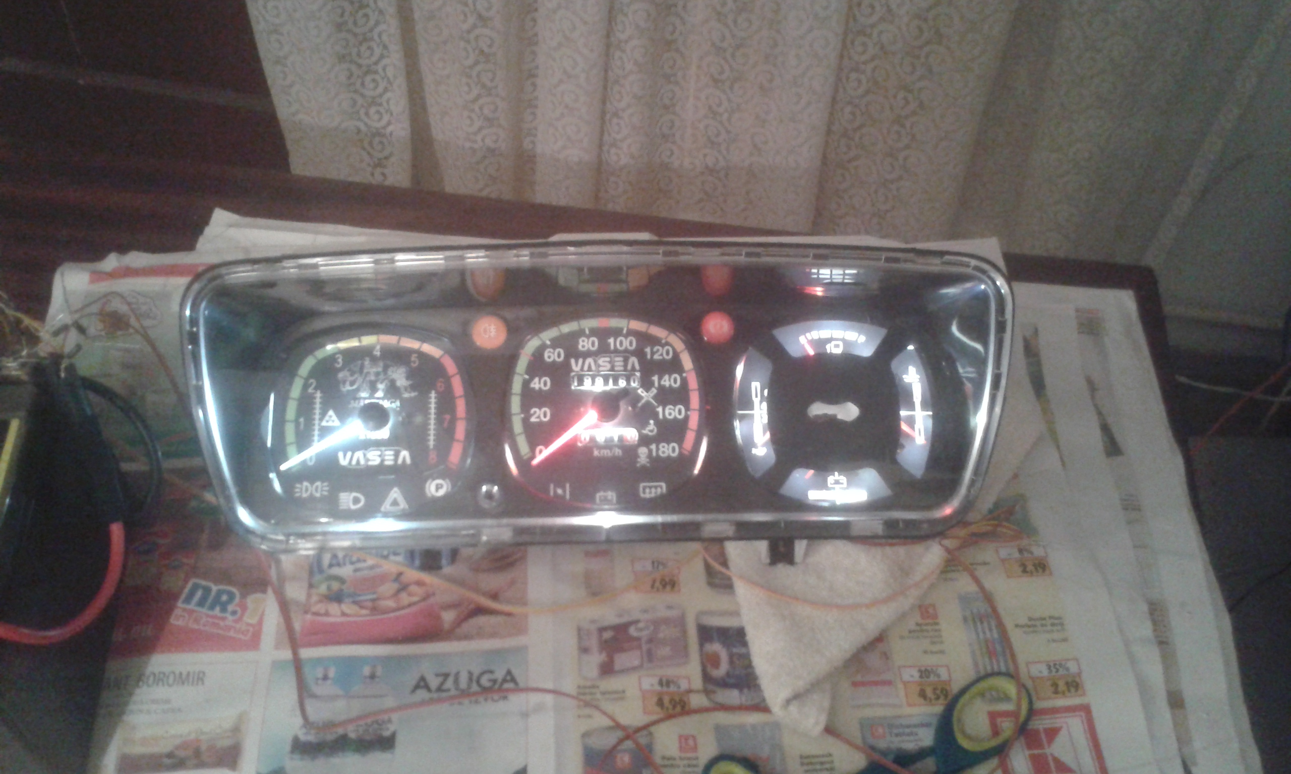
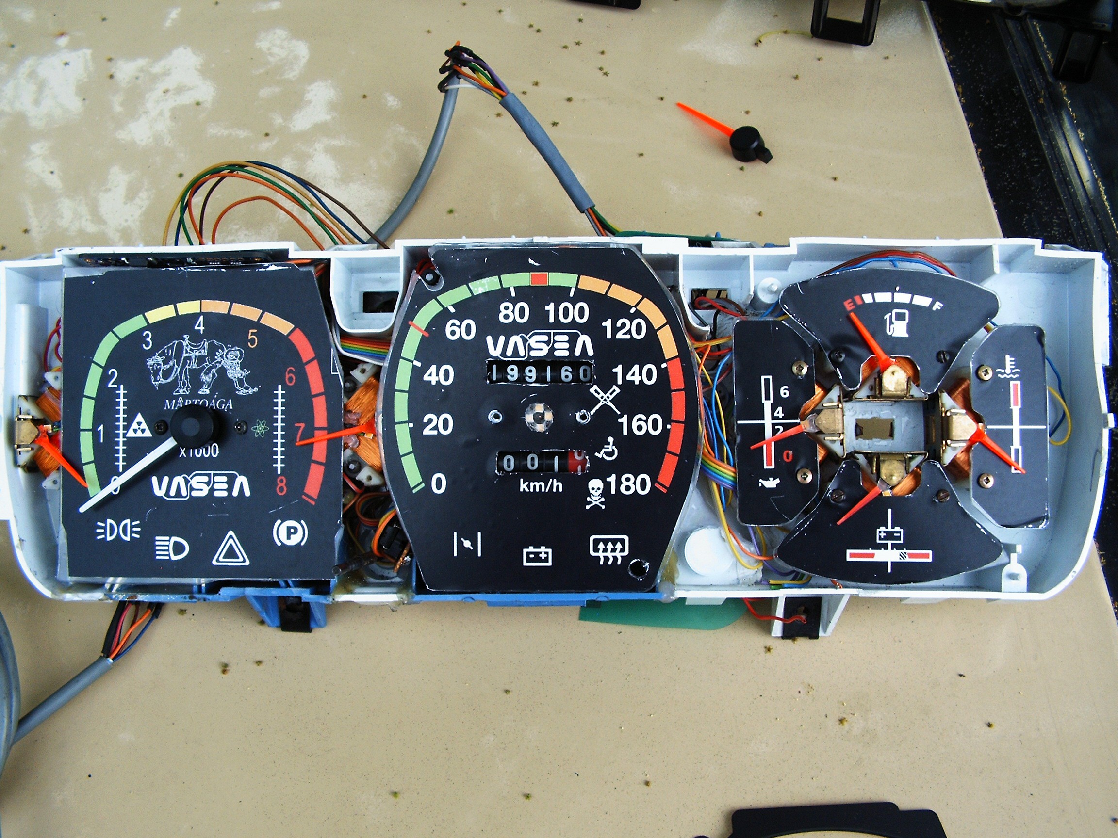
Dash board with new dials.It is impossible to view the blue drawings during day time, so changes are expected for dial colors.
On the RPM meter ( left side) there are the two additional gauges. Still not sure what to display with them, but they look nice. Probably radiation level and battery charging current.
![]()
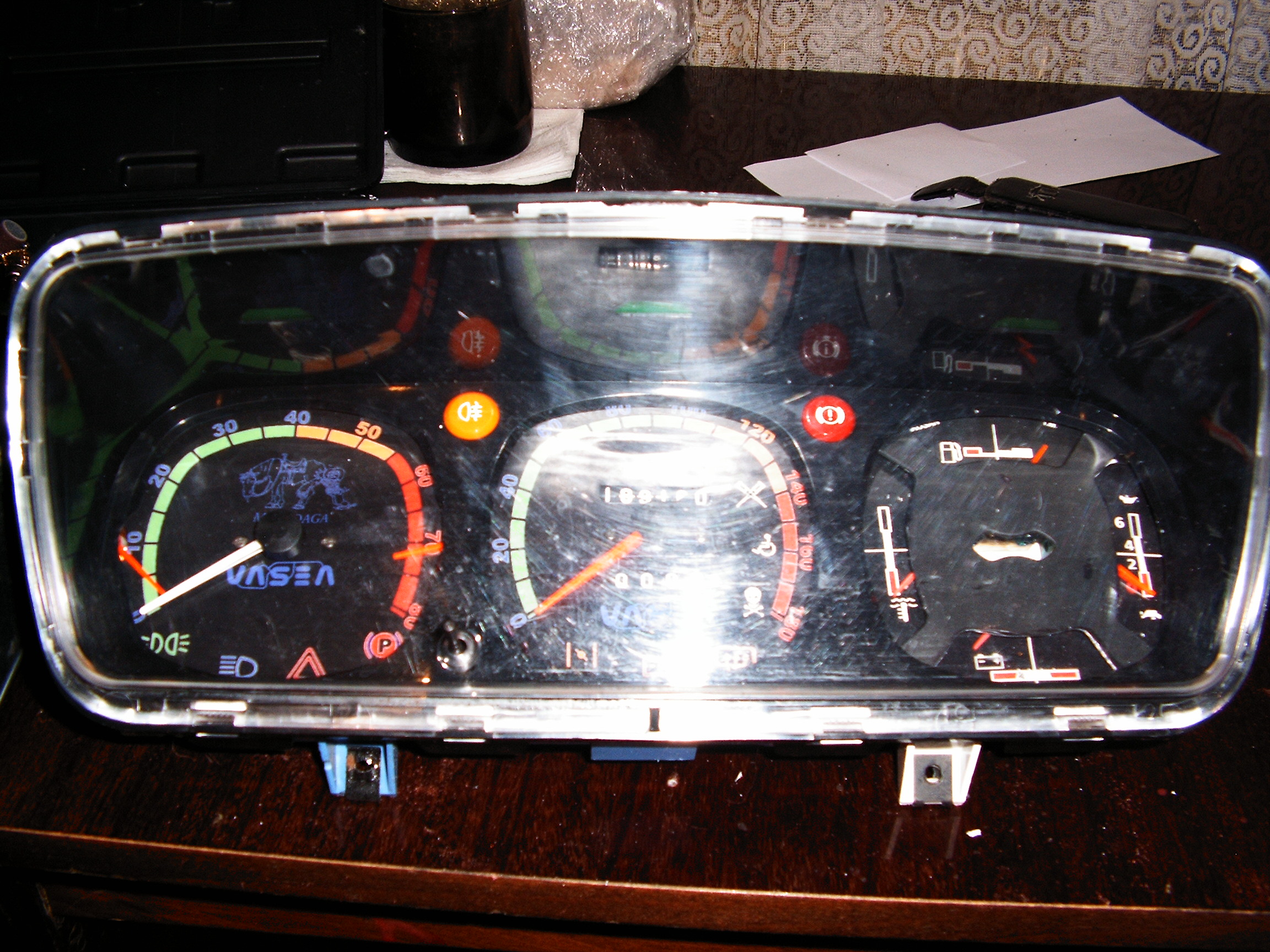
The picture below shows the other dash I keep in the car while upgrading the one above. So it's a second dash.
![]() And It looks better in reality.
And It looks better in reality.So an old dash (latest version) had only one speed gauge and one small gasoline gauge. I need 6 smaller gauges, so I had to dismantle the dashes from 6 other cars...
![]()
This is how it looks during day time.
![]() This is without background LED controls.
This is without background LED controls.The ready to print dials are stored in the Files section.
Somehow I missed the pictures and schematics for the back-side electric connections.
Later edit: traffic jams are unforgivable, I hope I will upload missing pics and schematics in time.
![]()
The A, C and E connectors are the originals one.
Added connector B (gauge PWM control) and D connector (Led PWM control).
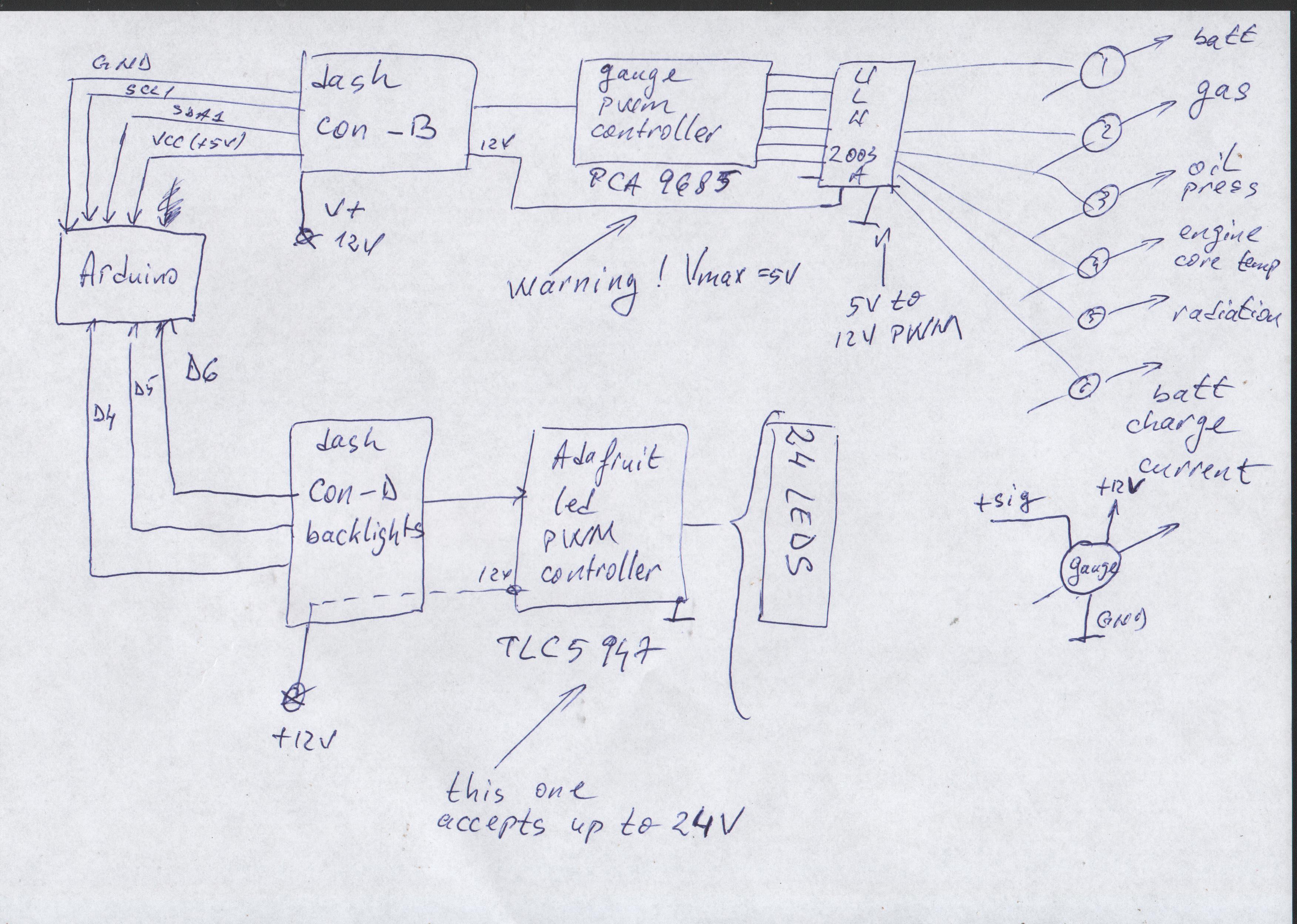
Schematic - hand drawn as usual:
![]()
The Arduino Due above will also send the lights and gauges parameters using my own designed Can Bus Protocol to the Raspberry Pi II embedded in the terminal.
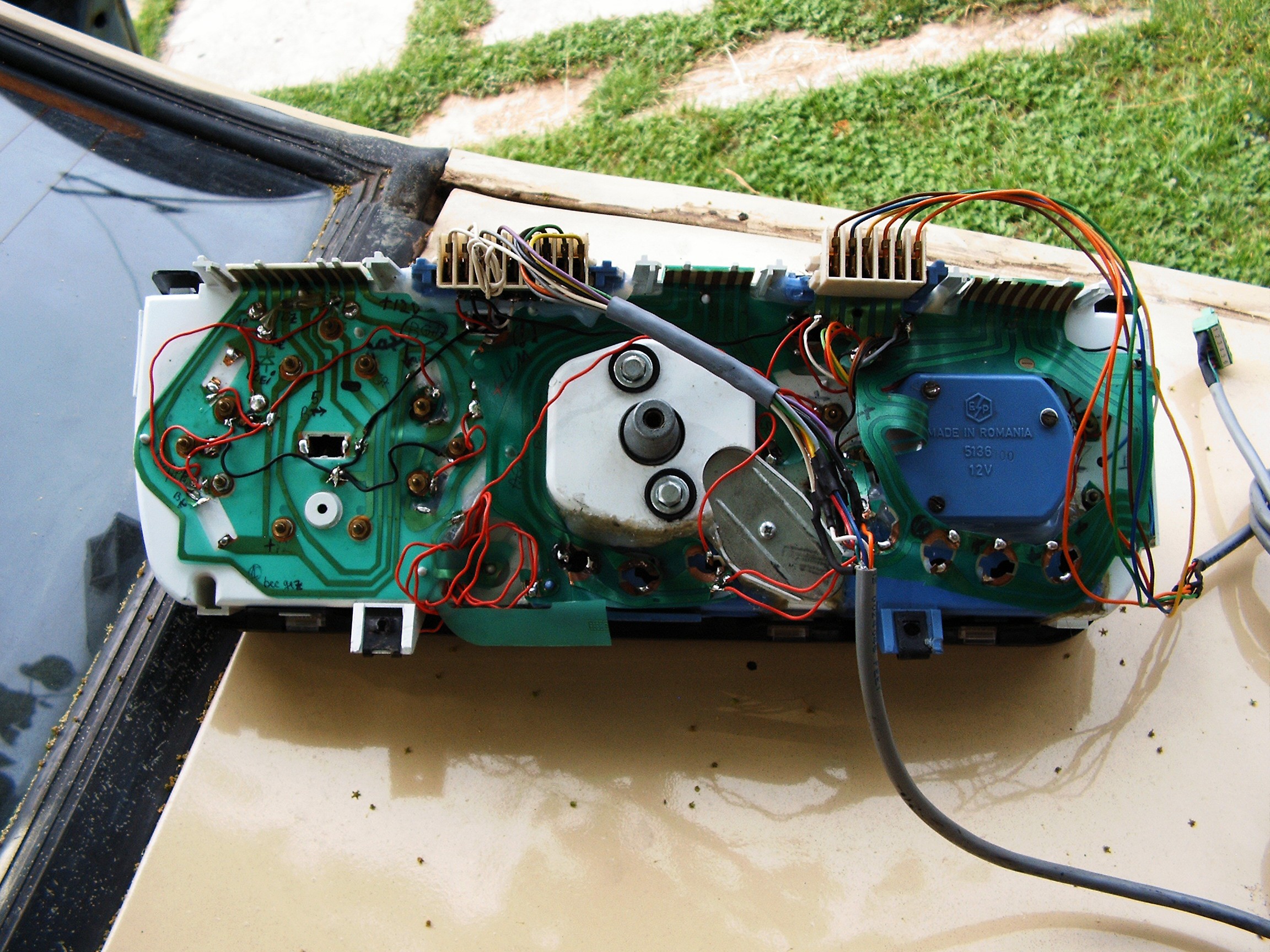
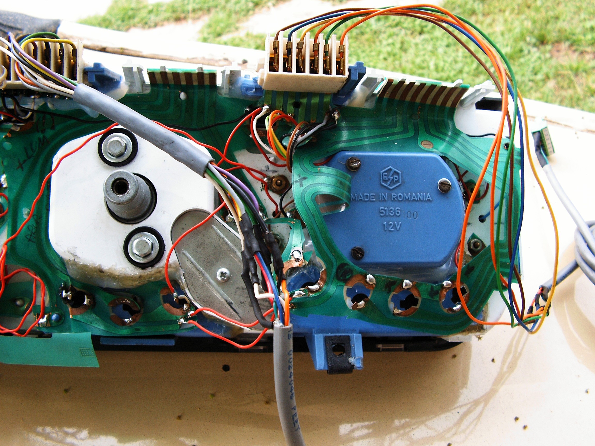
![]() Somehow I managed to modify the back flexible PCB according to the schematic above.
Somehow I managed to modify the back flexible PCB according to the schematic above.There are some holes in the bottom side, middle and right. Some 12Volts LEDs will be installed there, awaiting package to arrive.
![]()
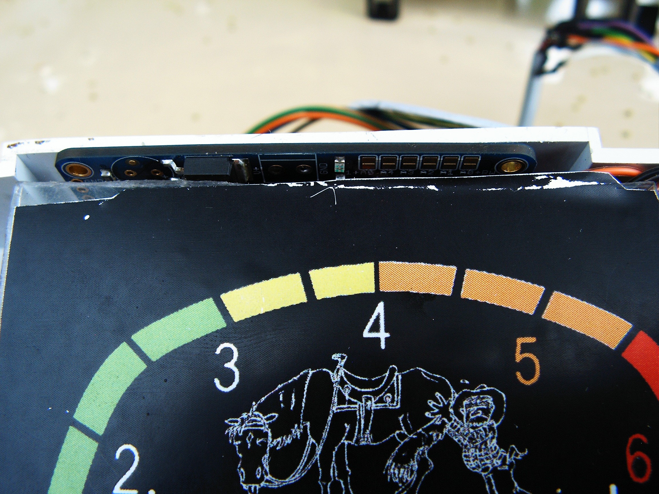
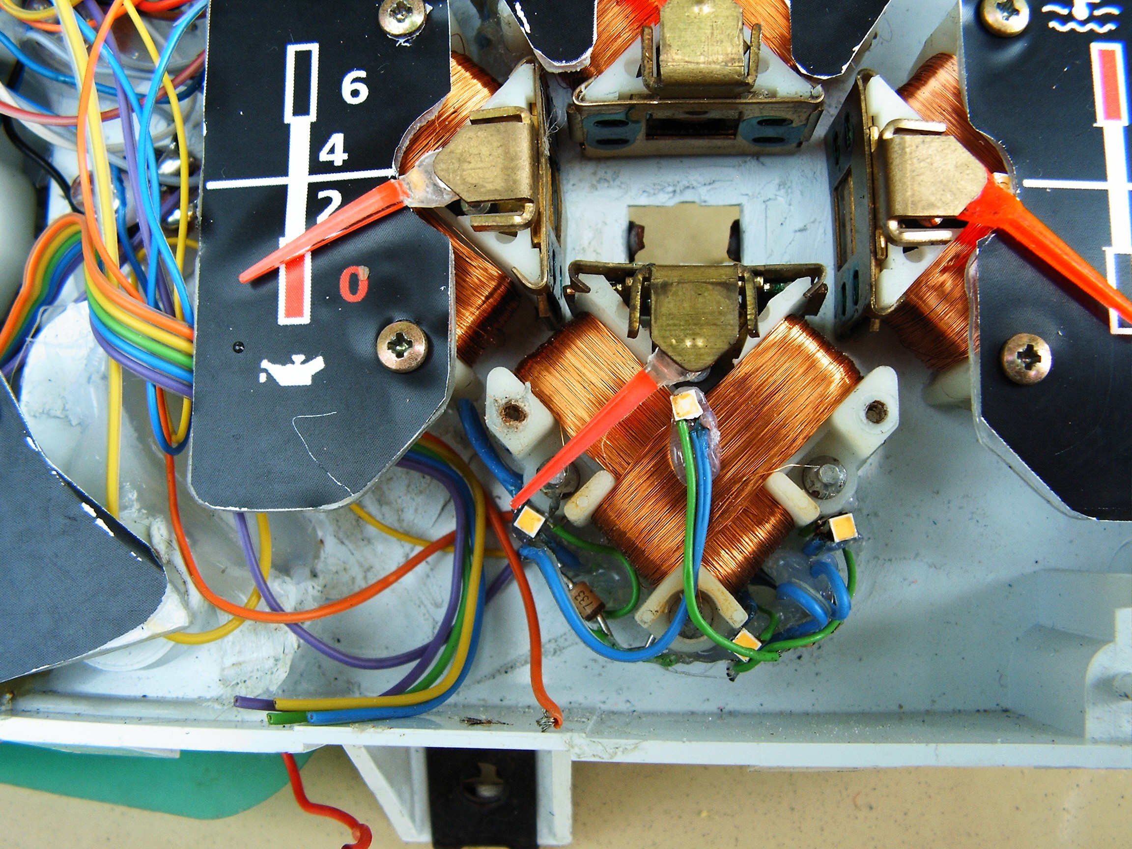
Close up view of the 4-gauge area. Middle hole is for emergency light signal led.
![]()
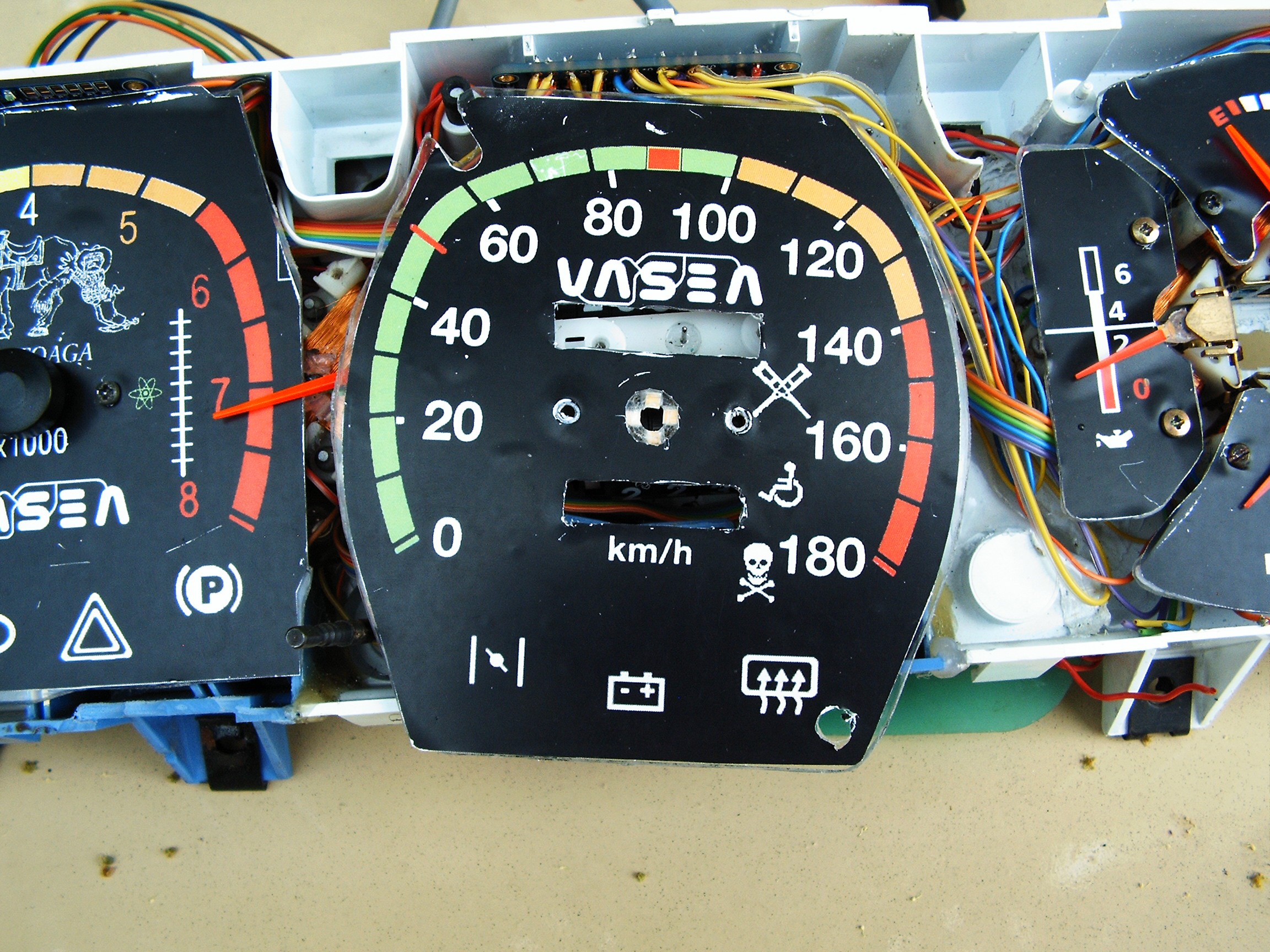
Speed meter and RPM+extra two gauges close-up view.
![]()
Notice the leds in the middle of the speed dial, under the pointer.
There are also leds under each pointer.
Dials were made from CD cases cut with the dremel tool.
![]()
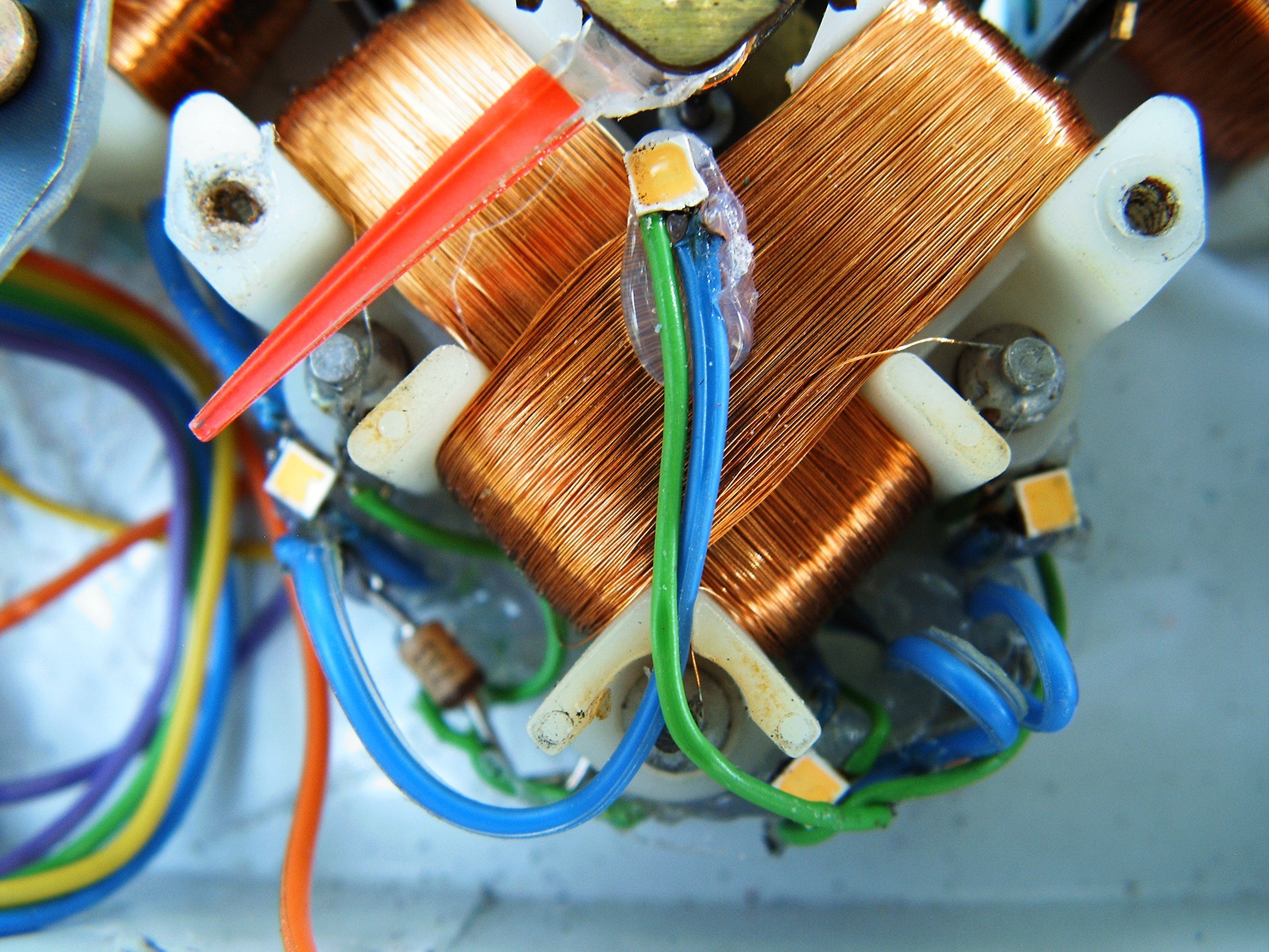
Again close view of the speed dial leds
![]()
back side...
![]()
Back light for speed dial - there are some 5mm leds between the wires.
On top - led PWM controller
![]()
Gauge PWM controller, behind the RPM dial. And yes, that's an old lazy horse.
![]()
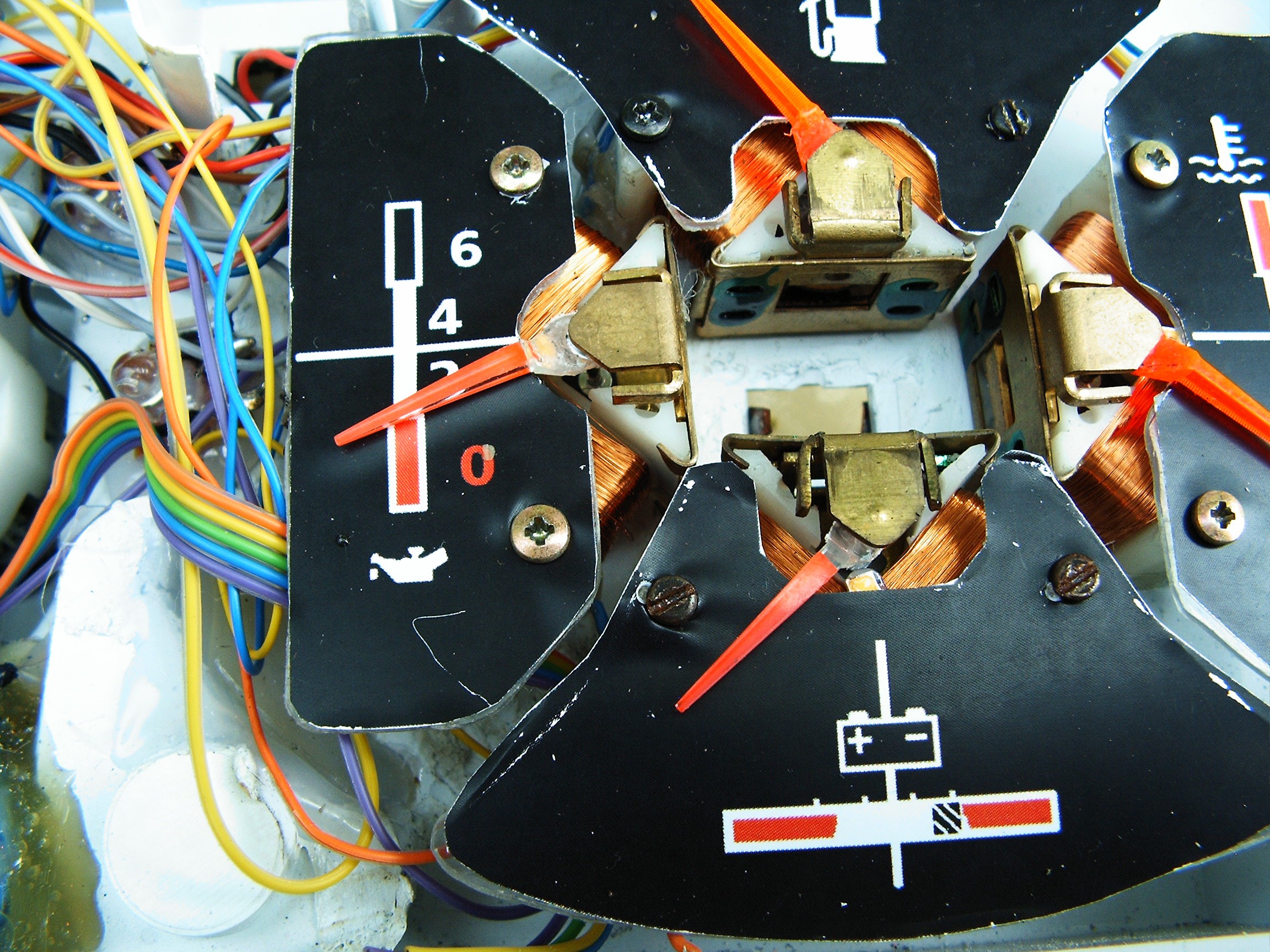
Can you see the leds under the pointer needles?
![]()
Battery dial removed, there are 4 leds.
![]()
Close view of the leds.
Finally I started to learn how to adjust camera settings to focus properly.
![]()
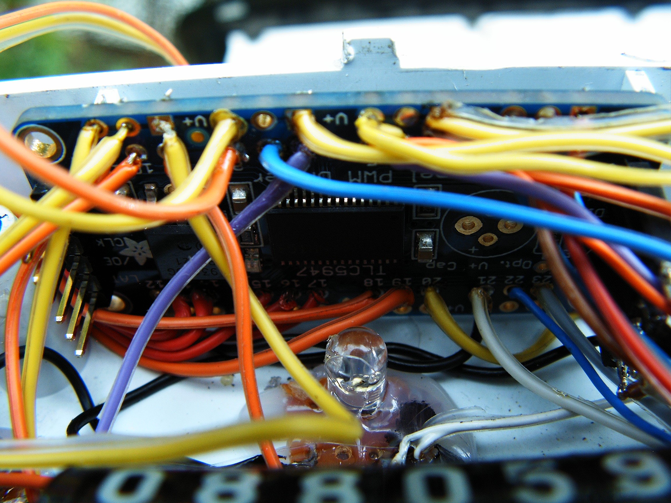
Again - close view of the TLC5947 LED PWM controller.
![]()
And of course the ULN2003A which converts 5V PWM signals to 12V so they are fit for the gauge. I manage to find a place for it, hidden in some corner.
[END OF TRANSMISSION]
______________________________________
kernel panic: improbability coefficient below zero
-
Building the terminal
05/30/2016 at 00:25 • 2 commentsAllright. The first round reward was like a deep fresh air breathe, because I managed to fix most of the bad issues of the automobile mechanics. These are the completed steps:
- front and back springs replacement;
- rear axle replacement;
- new carburetor;
- most of the engine gaskets replaced;
- the entire steering mechanics upgraded;
- brake system upgraded;
- finalize all paperwork plus pay legal taxes in order to receive a big place to setup a local hacker space and laboratory.
And of course a nice romantic dinner for my lovely wife, which can still not believe how such a competition and a reward is possible for such an old rusty vehicle - which by the way caught rust AGAIN at trunk side. It needs serious body repairs [lot of time, a lot of money, not sure how seriously the work is done] , or even a new body [less money, less time, but it requires many taxes for the local "DMV" authority -Romanian Automotive Registry or the "RAR"]. There are some left-overs at the Dacia Factory, it may be possible to find something.
So good news: I am no longer forced to work under cover. She now tolerates my operation and even helps me by using her strong financial accounting background experience.
Now back to serious stuff. It's time to show you people how I built the computer terminal. Basically it's a dual-oscilloscope+color television used as a composite monitor which receives video signal from a RasPI II - B. It also houses the Arduino and a 12V to 5V power regulator to keep both working in stable conditions.
Unfortunately... reward did not arrive in time to build the oscilloscopes. So I will keep this step for the next round - Citizen Scientist - if the jury will again be merciful.
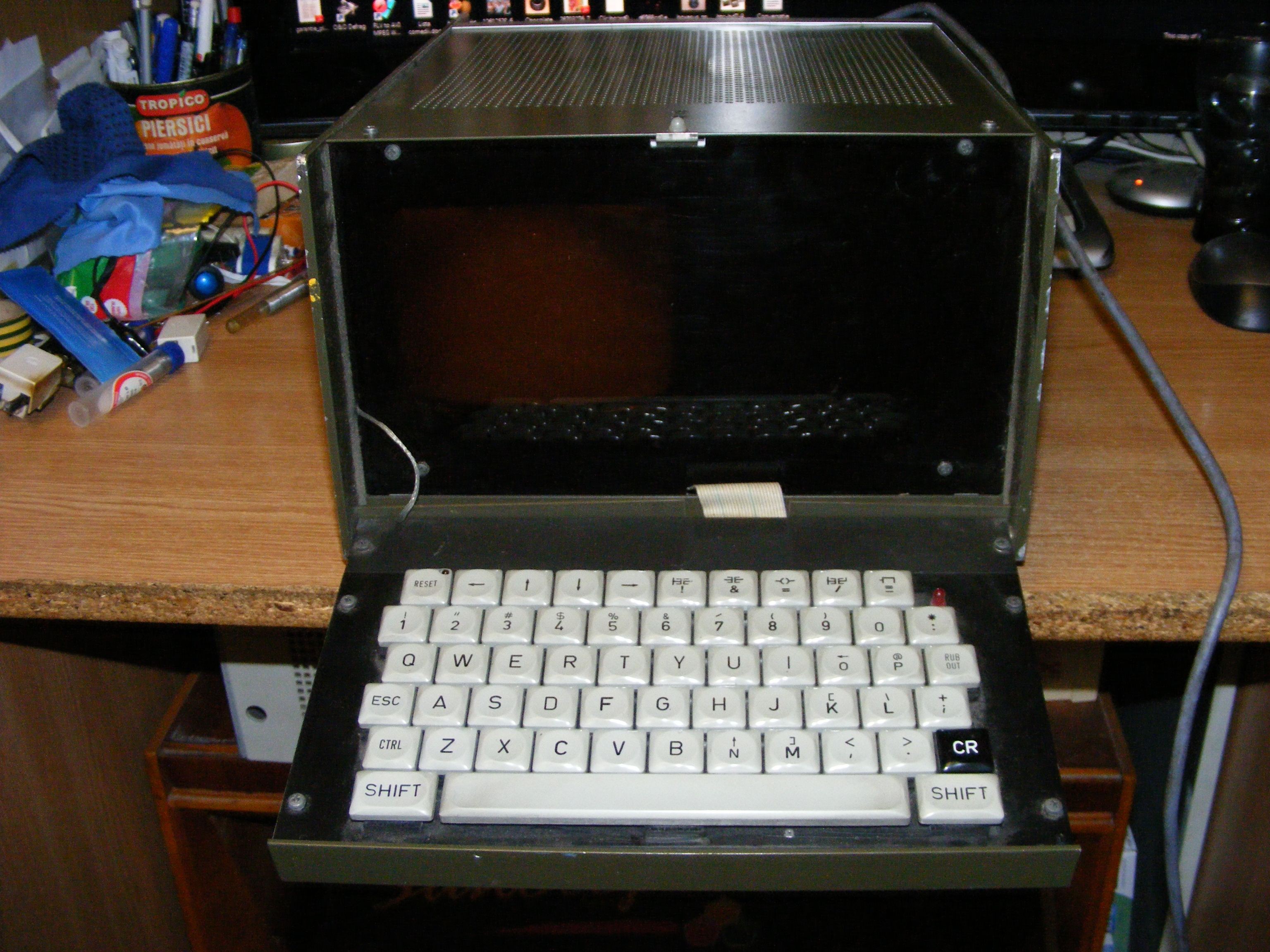
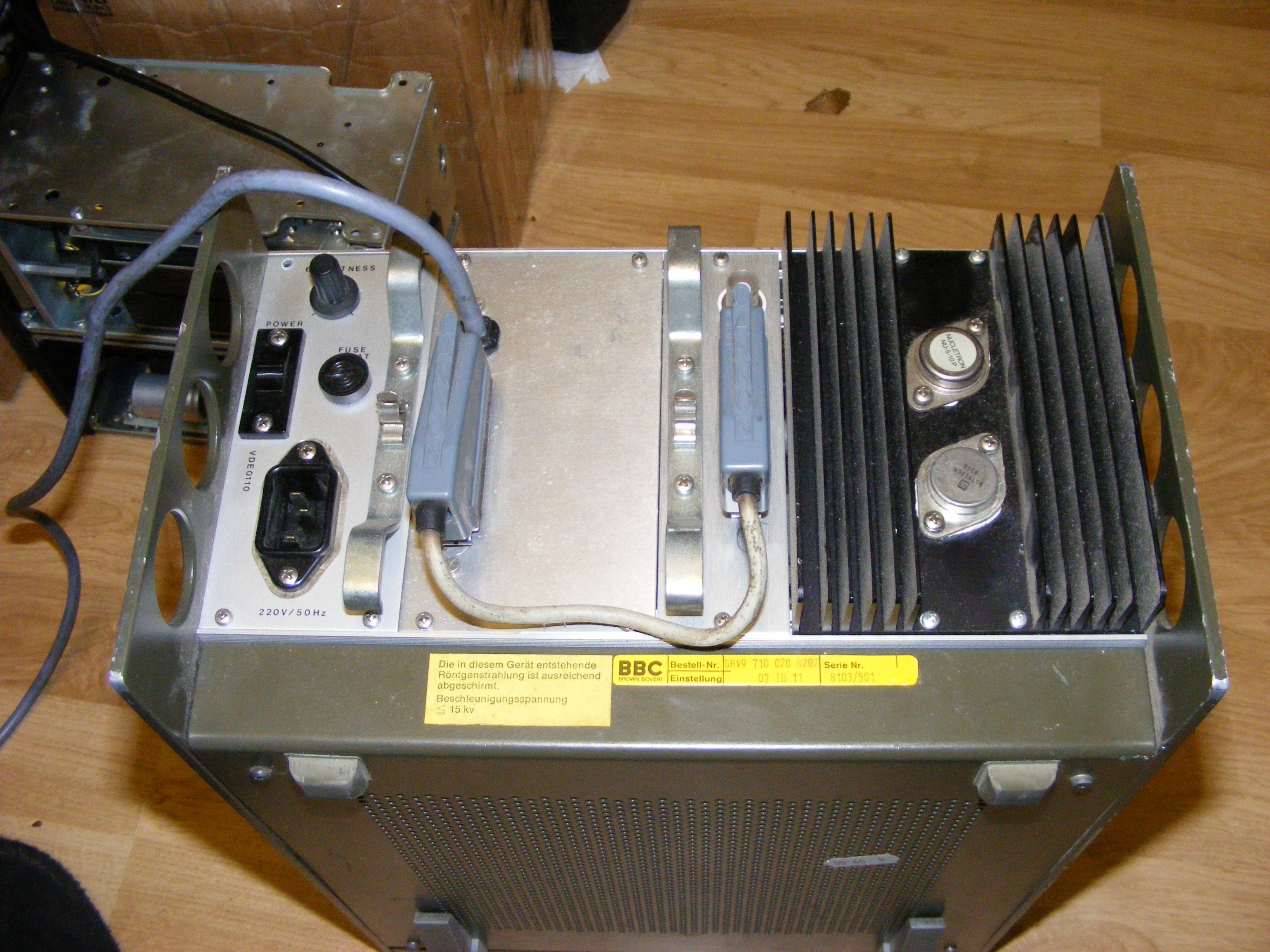
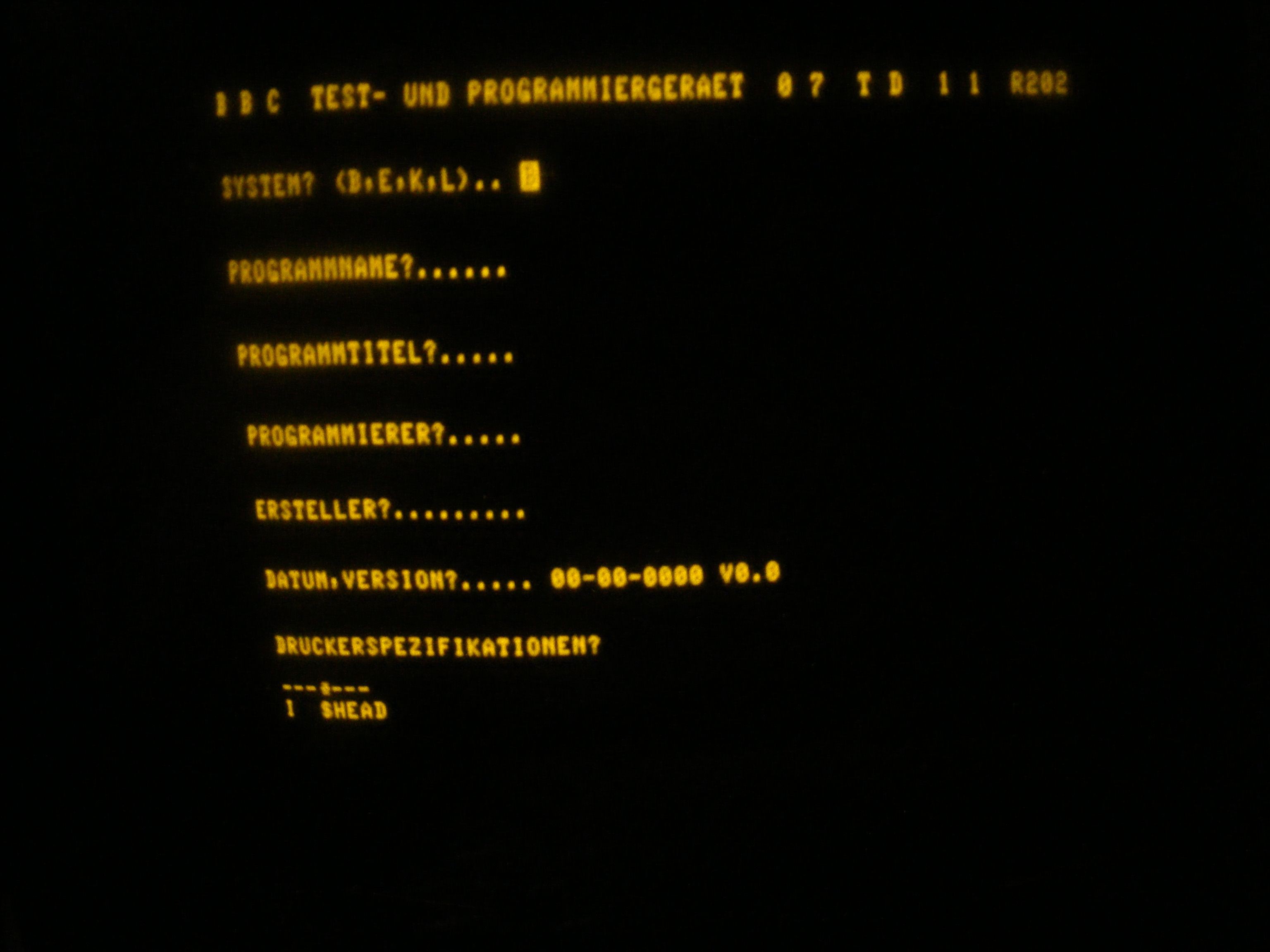
Around a year ago, a friend sent me this little monster: an old missile guiding system programmer made in 1982 in Western Germany. It has some console program, a monochrome monitor and a Z80-based main board.
![]()
![]()
Under the bottom cover there's a motherboard with a lot of EEPROMS and a Z80CPU.
![]()
![]()
These lateral boards are the interface with the rocket guidance. I have seen soviet missile tech from that era but it was entirely subminiature vacuum-tube based but they also had programming ports. This equipment was manufactured in Western Germany in 1982.
This is the first screen of the guidance programming:
![]()
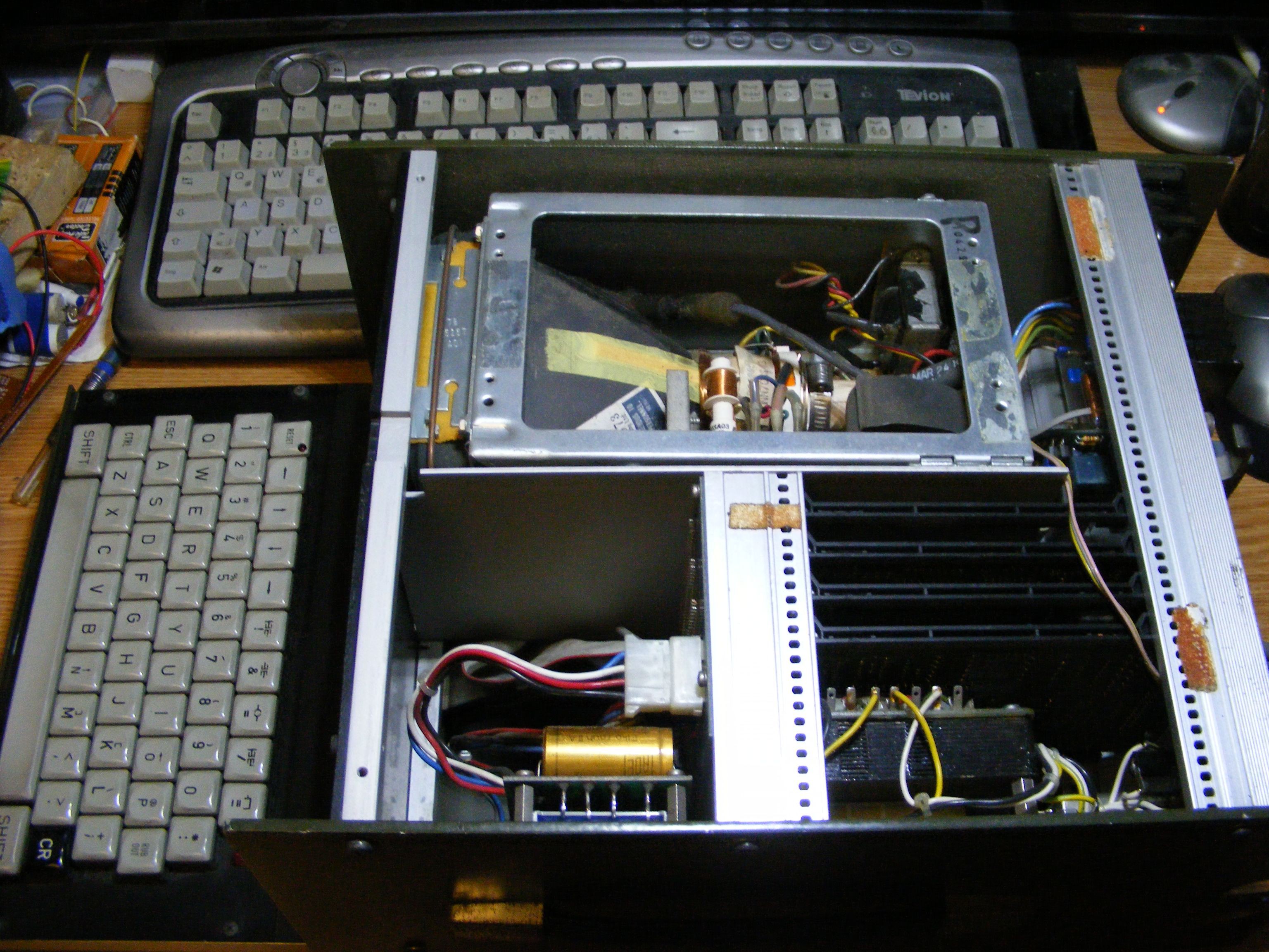
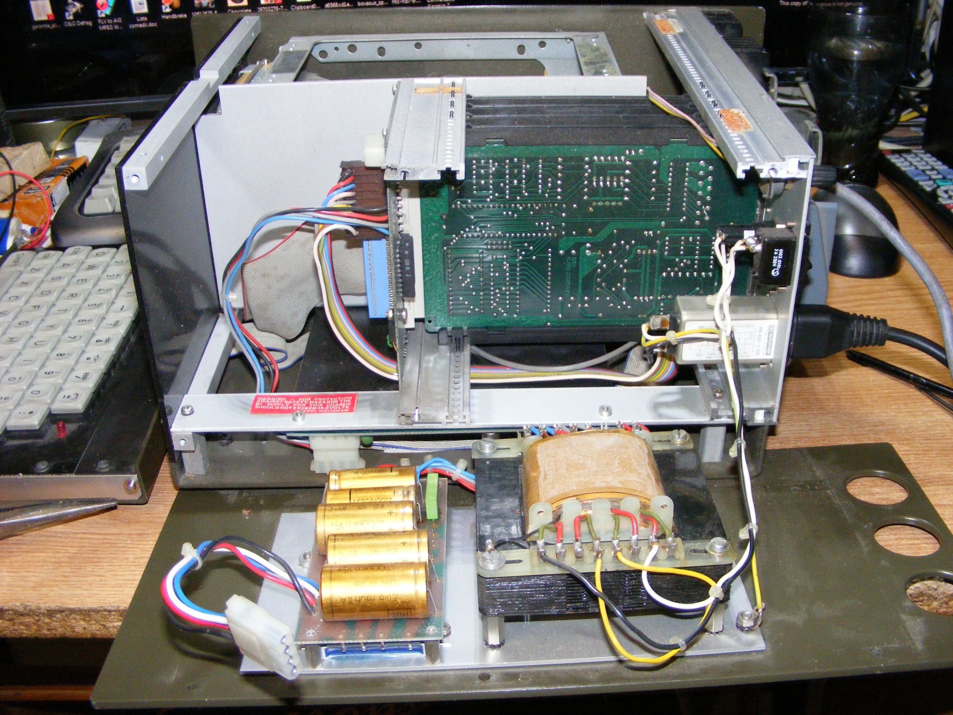
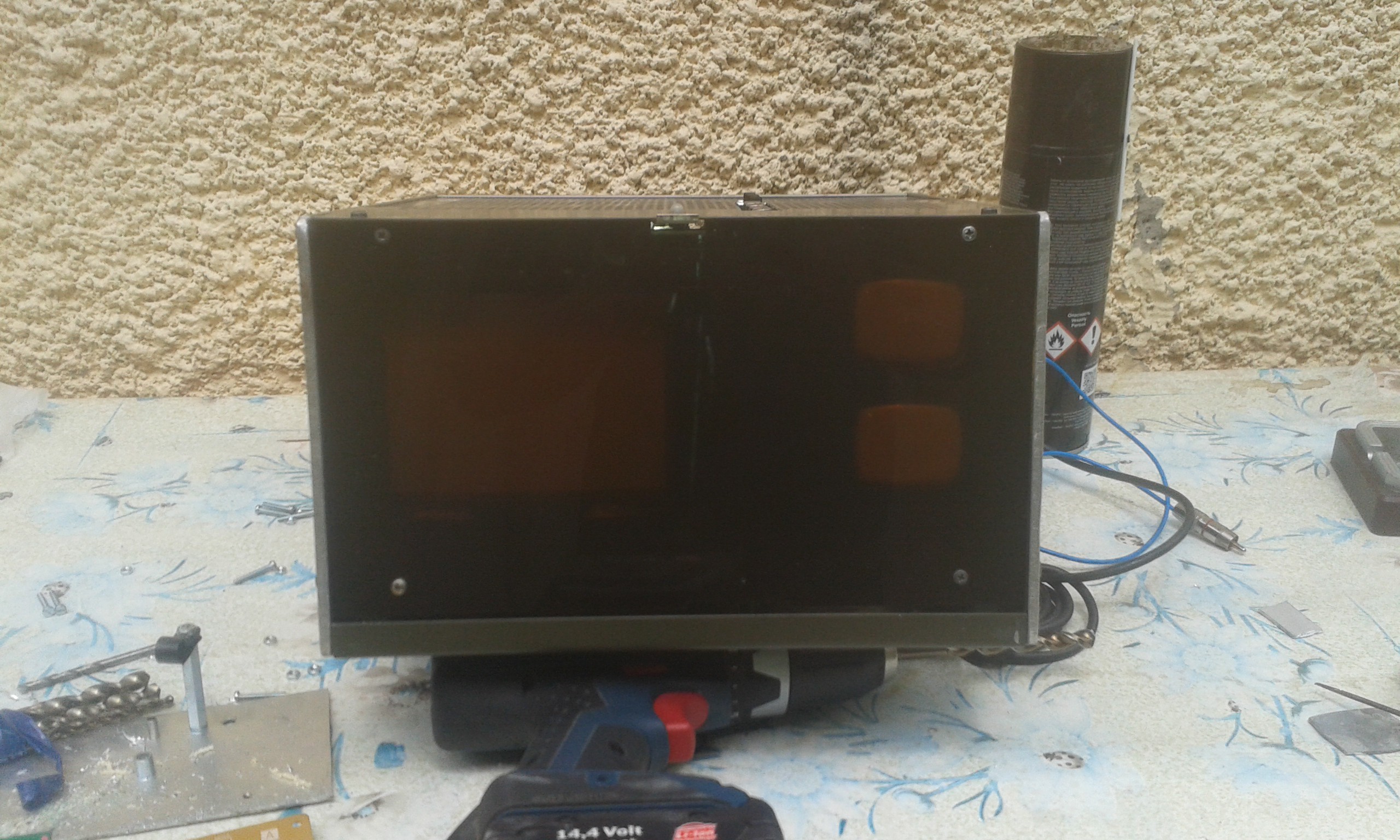
So I took everything out and inserted a 5" color CRT tube from some Japanese TV branded as "Crown". And of course the TV electronics.
I kept the old monitor plus boards in some box. Maybe I will add an extra-CRT for retro satellite navigation as @Benchoff suggested.
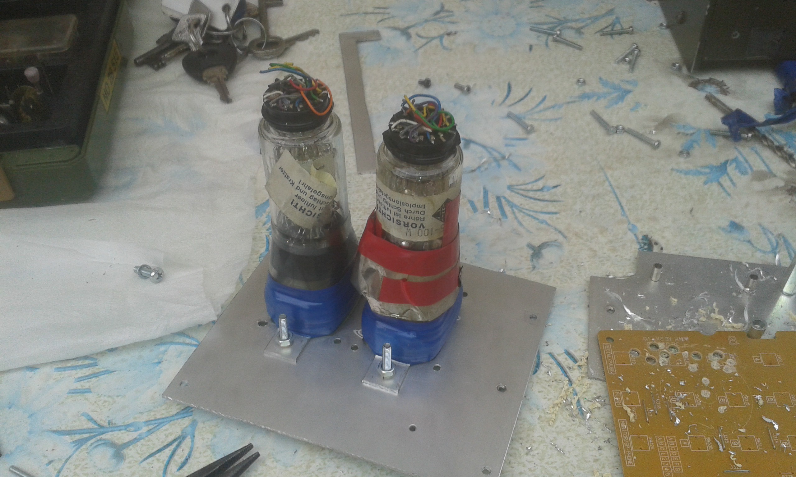
Following the concept desigh drawings, two additional CRTs (DS5-100W) were added:
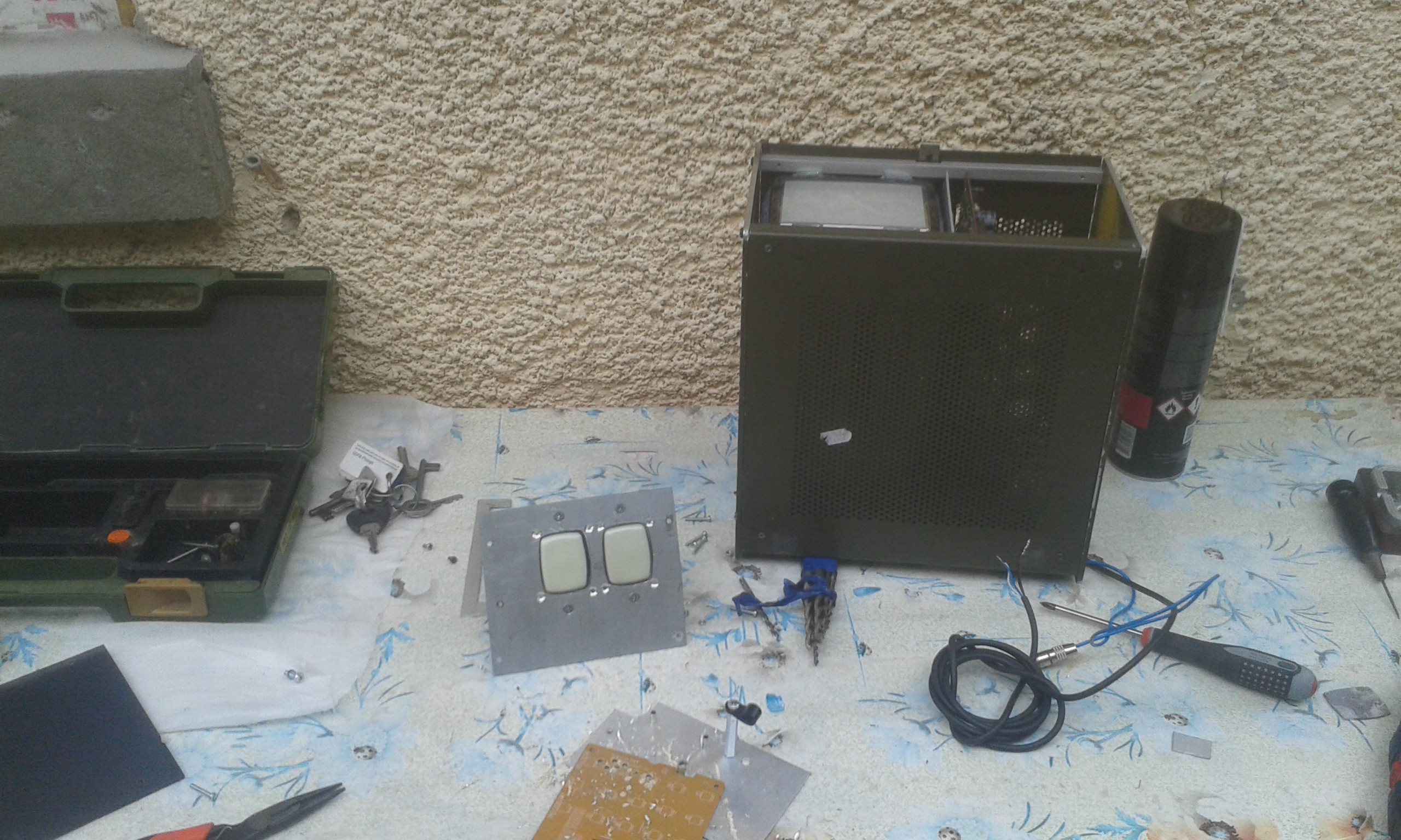
![]()
That aluminum sheet was cut by hand using my small dremel tool.
![]()
![]()
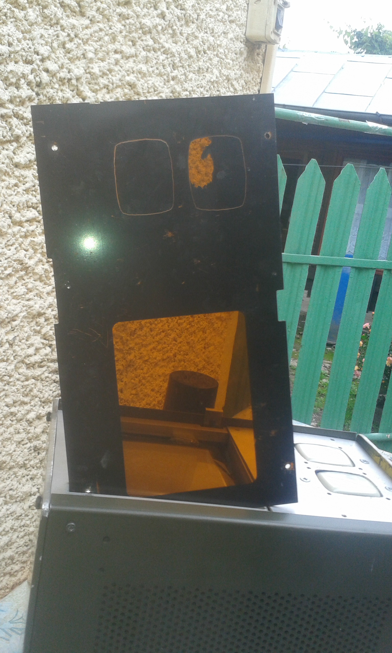
The mask needs an update:
![]()
The paint removal was performed with a razor and tons of patience.
![]()
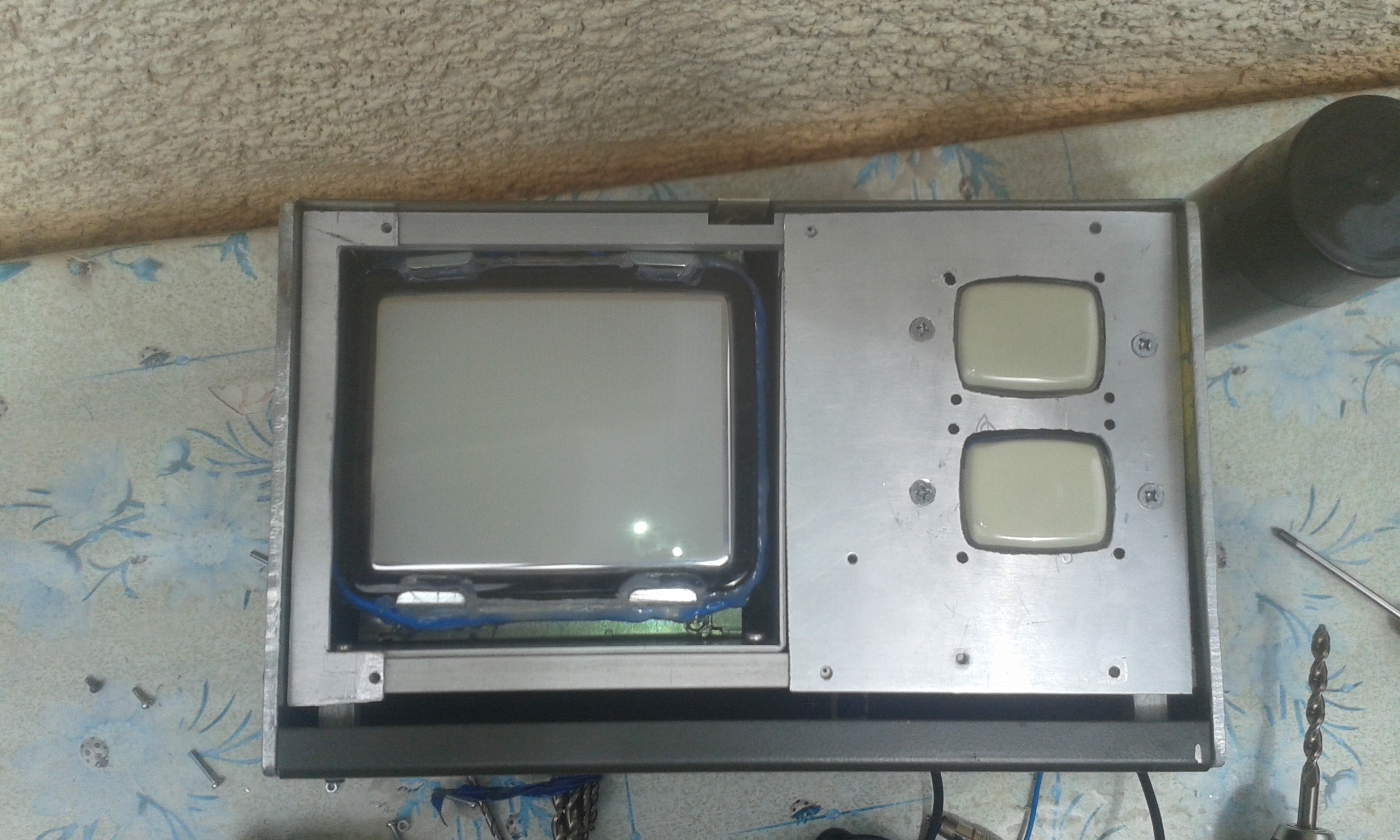
And this is how it looks like.
Of course I will need a new plexiglass mask. This one has a strange property - it removes most of the blue color and some percentage of red color, resulting a nice sepia effect which I am not sure I want to keep. So please advise.
![]()
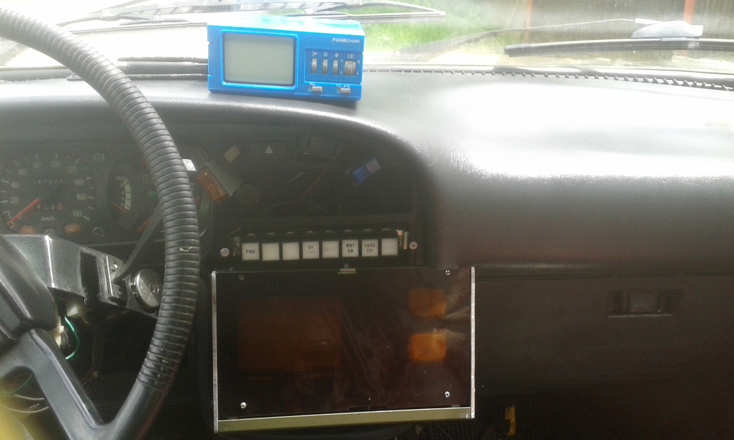
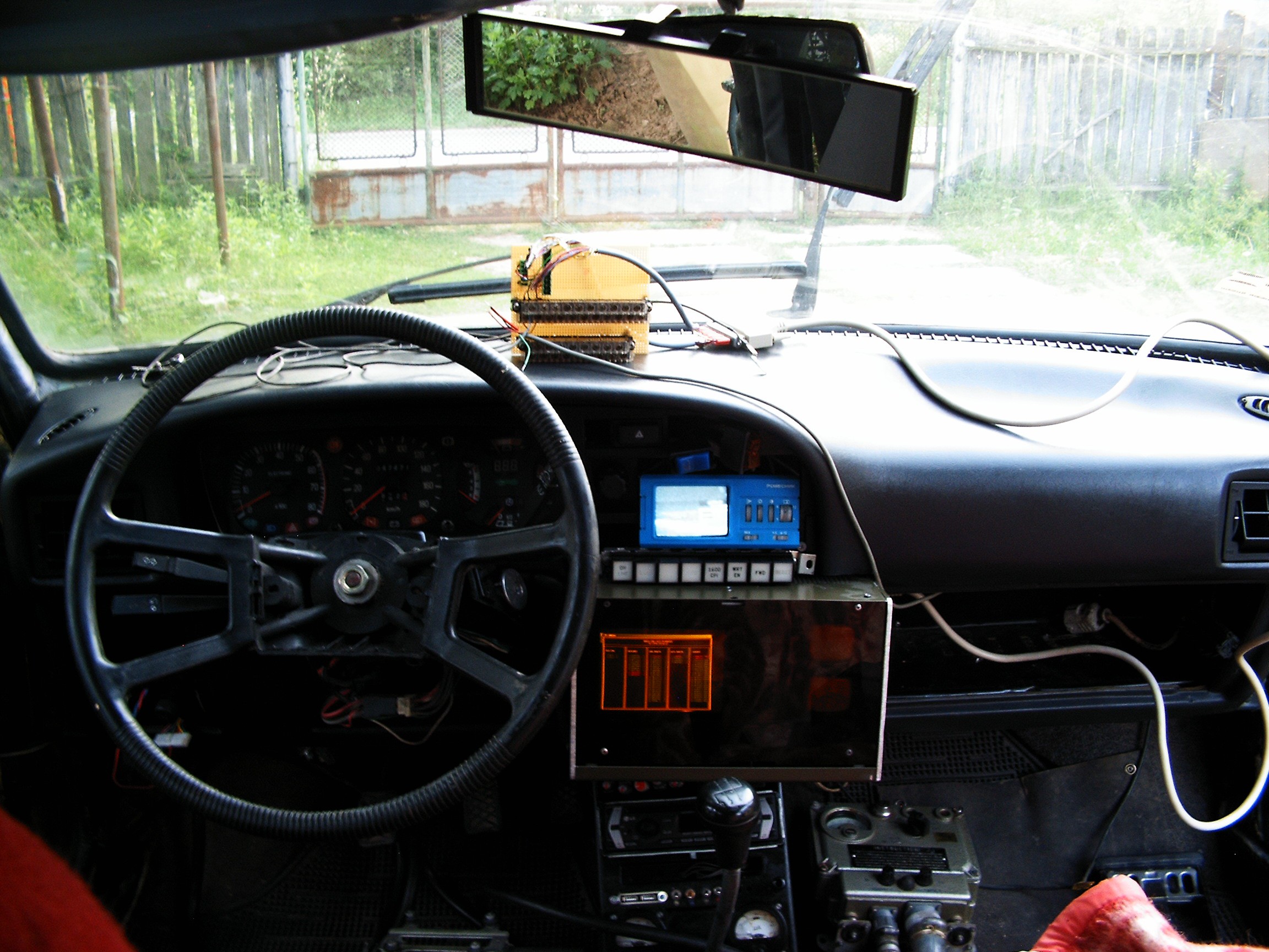
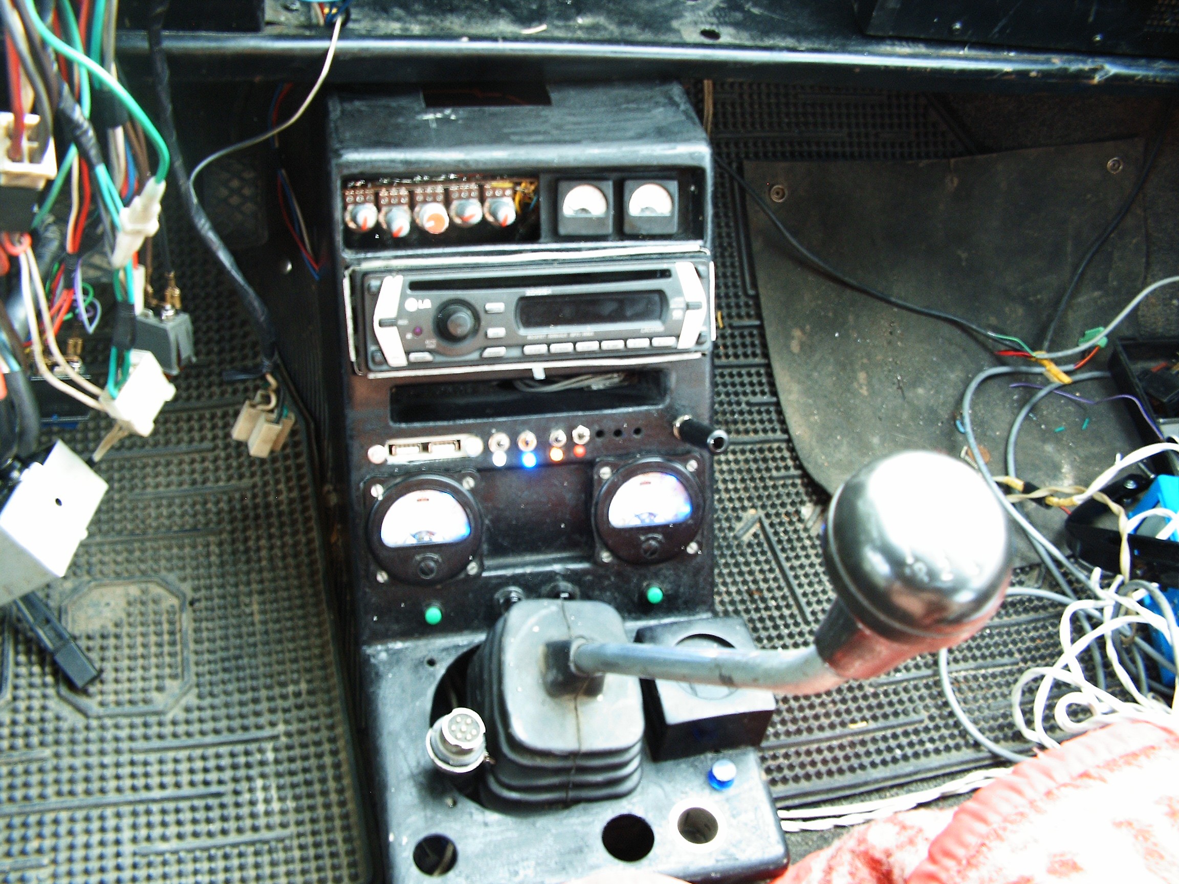
Placed in the car, the tiny terminal looks amazing.
I had to remove the keyboard, it was uncomfortable while shifting the gears. The keypad above is enough.
Due to the late arrival of the first round reward, I was unable to order the parts to build the electronics for the two CRTs. For now they are just for decoration, no oscilloscopes at this time.
![]()
RasPI 1-A booting FreeBSD 11.0-CURRENT, video connected to AV-IN.
The first key in the left (labeled as FWD) starts the system. The other key functions are as following:
1. Vehicle cabin ventilator start/stop;
2. Rear window defroster start/stop;
3. fog lights start/stop;
4. 220Volts start/stop;
5. CB Radio on/off;
6. Radiation detector;
7. Terminal screens cycling - switch between diagnosis programs, dials, gauges, graphs.
Keys will be re-labeled. And of course - work in progress - it would be nice for each button key to be illuminated. Still not sure about the color. White or green? Please advise.
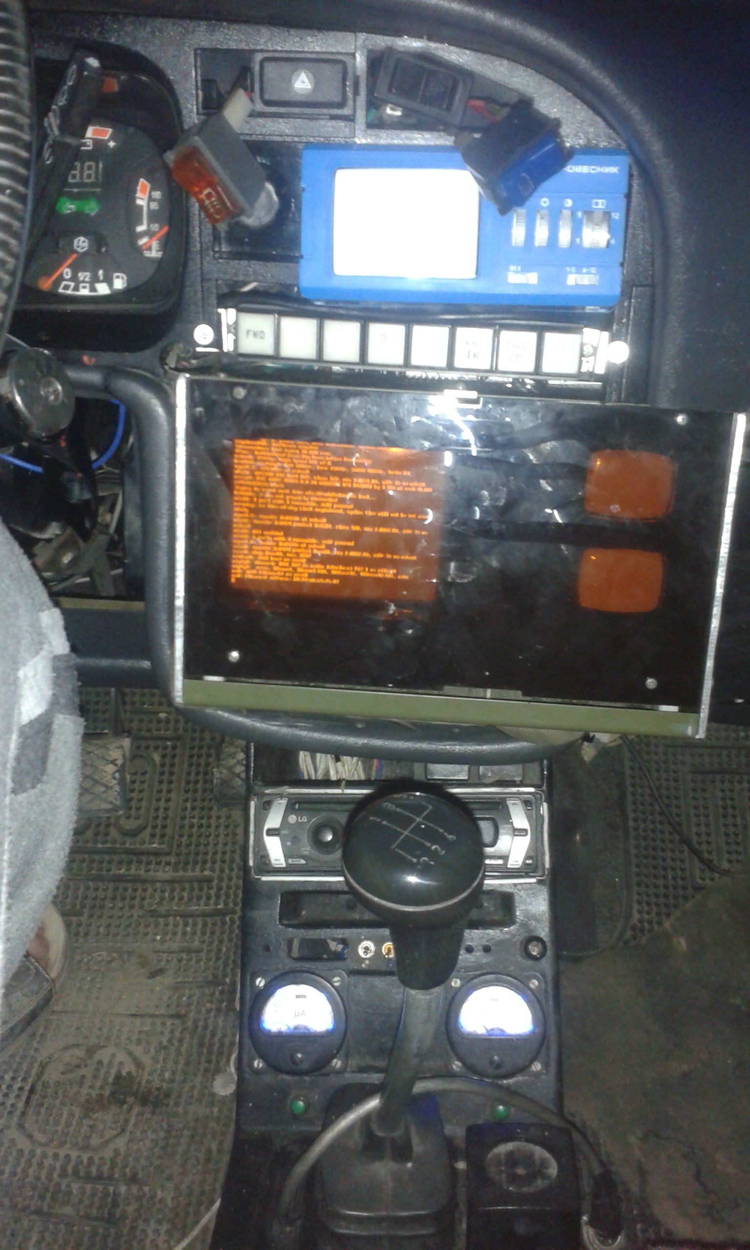
![]()
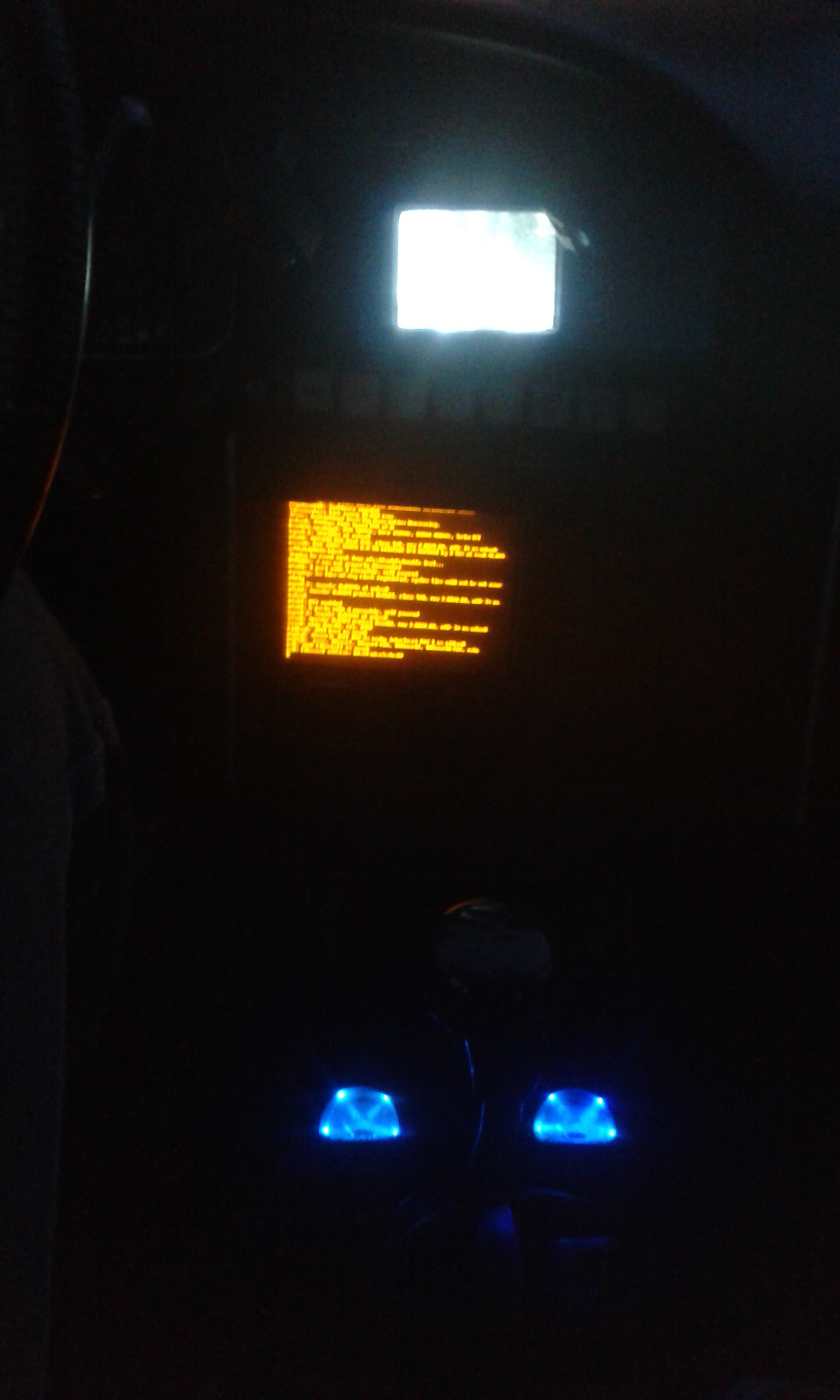
At night time it looks SF-like.
![]()
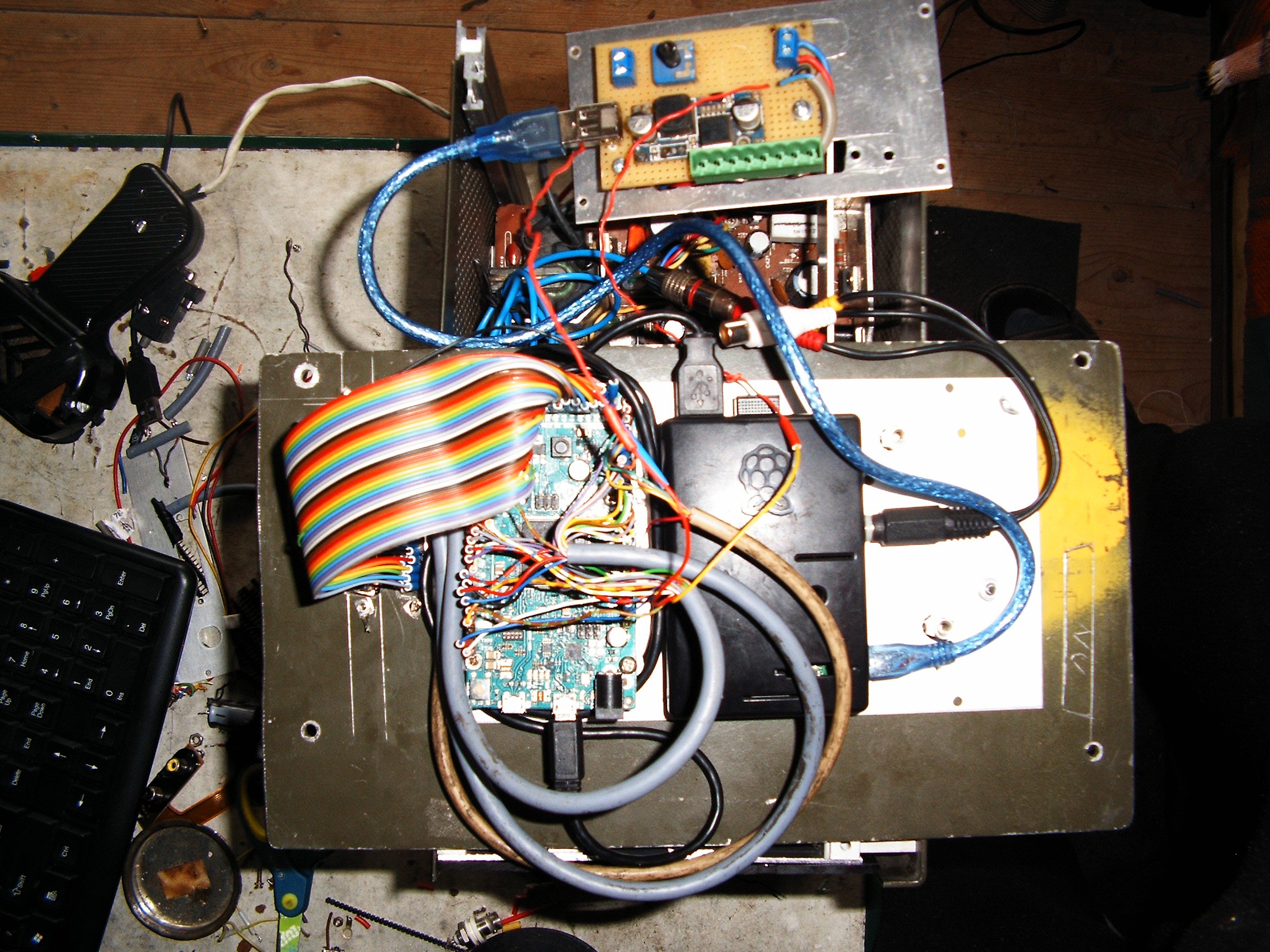
We have my big love - Arduino Due, a RasPI 2 and a 12V to 5V power regulator. Green connector is 12V to power both the color monitor and the small blue TV.
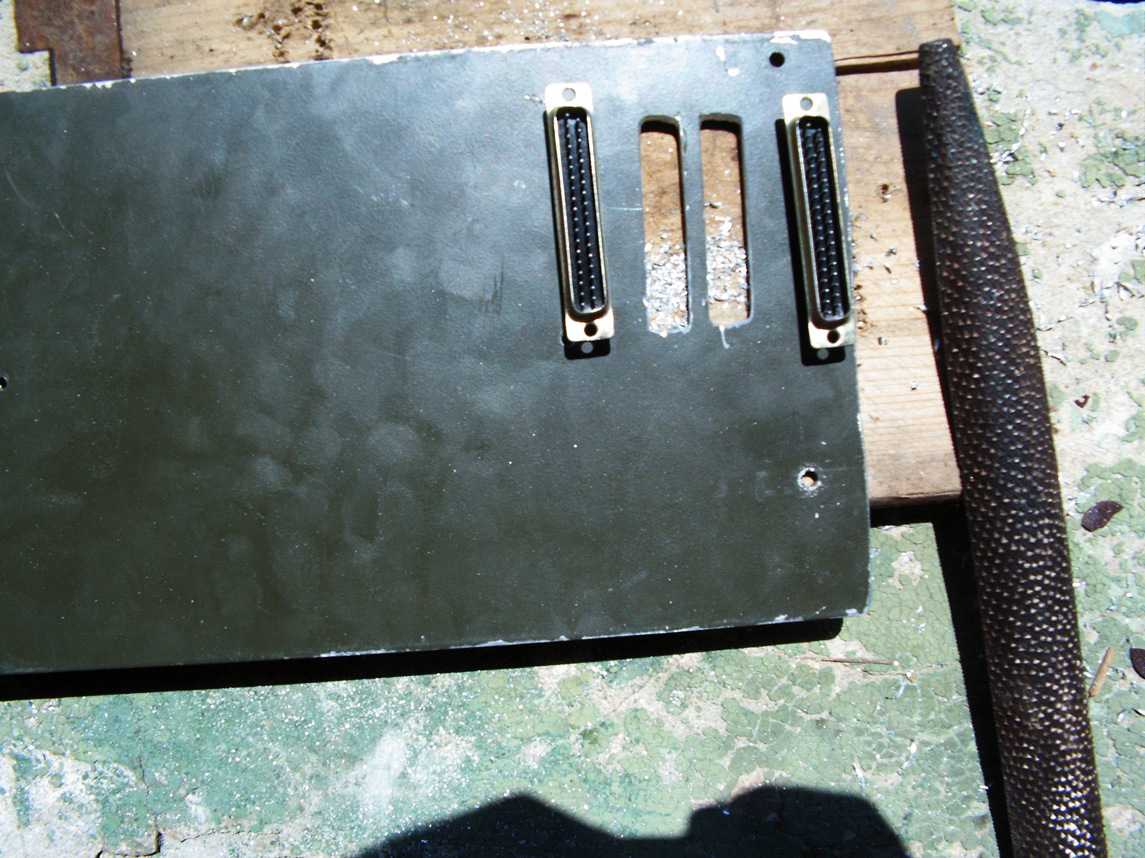
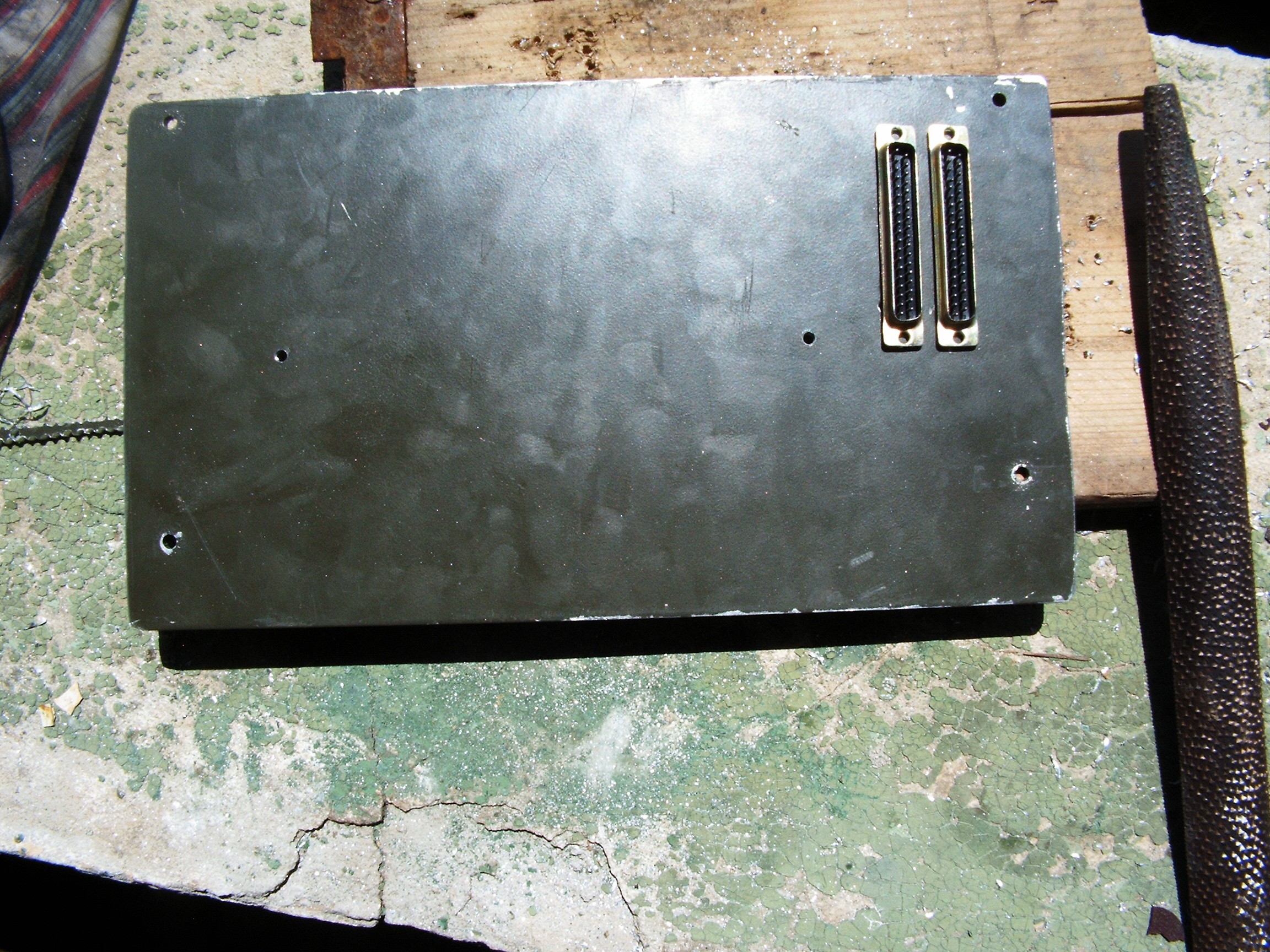
Somehow I must interface the Arduino with the outer world. I don't want to take out the terminal computer each time I want to install a new sensor. Two DB37 connectors would be perfect:
- one DB37M for analog inputs and the standard digital i/o pins (those common with the others Arduinos) - this one will have its connections vibration-protected with red extra-coatings;
- one DB37F for the extra-ports specific to Arduino Due only. This one will have its connections vibration-protected with blue extra-coatings.
And of course a big pile of papers where I will draw some tables and chose which i/o pin goes to which DB37 pin.
Whenever I want to connect new stuff, I just play in the Junction Box. No more connectors? No problem, I build another junction box.
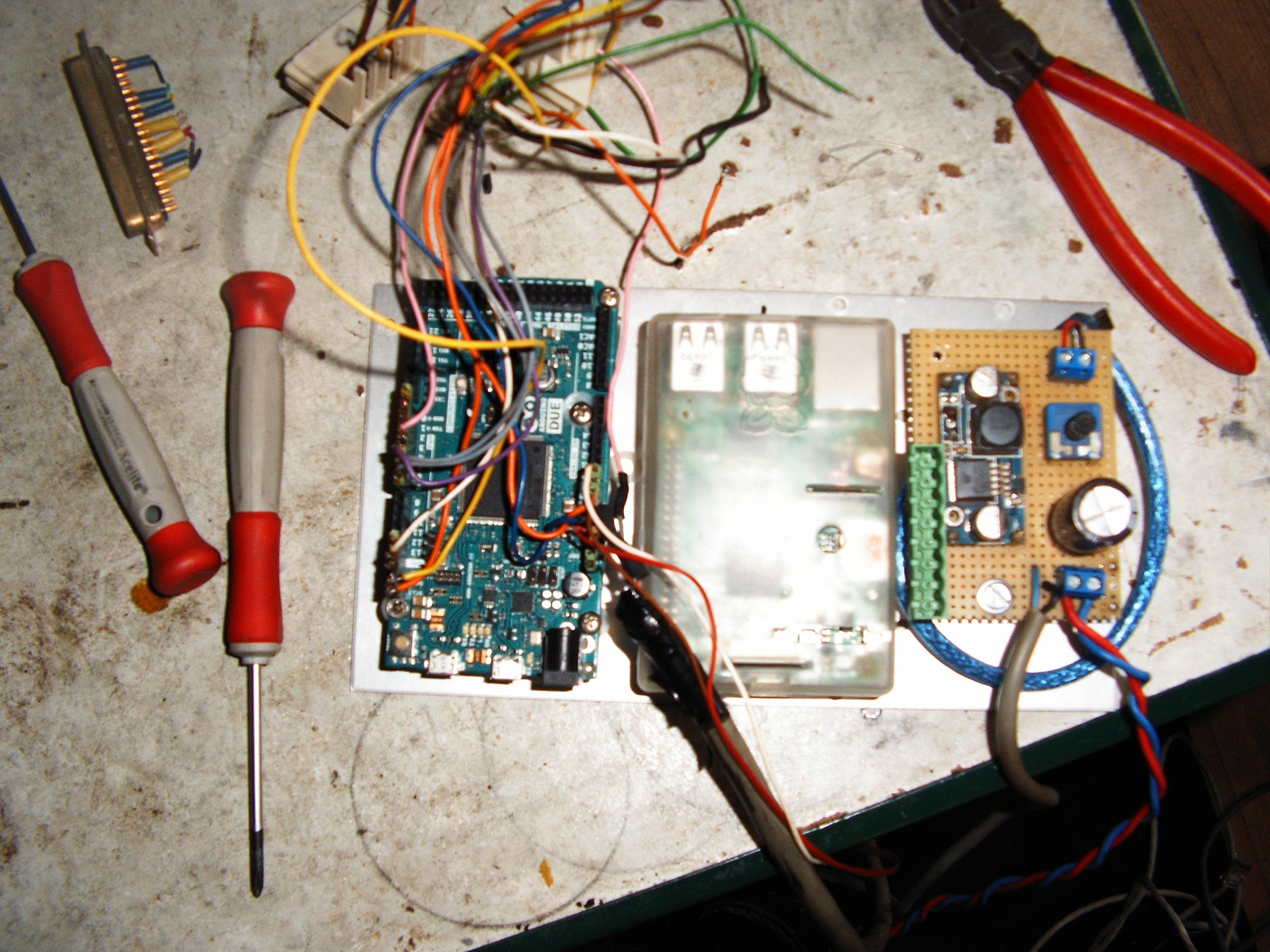
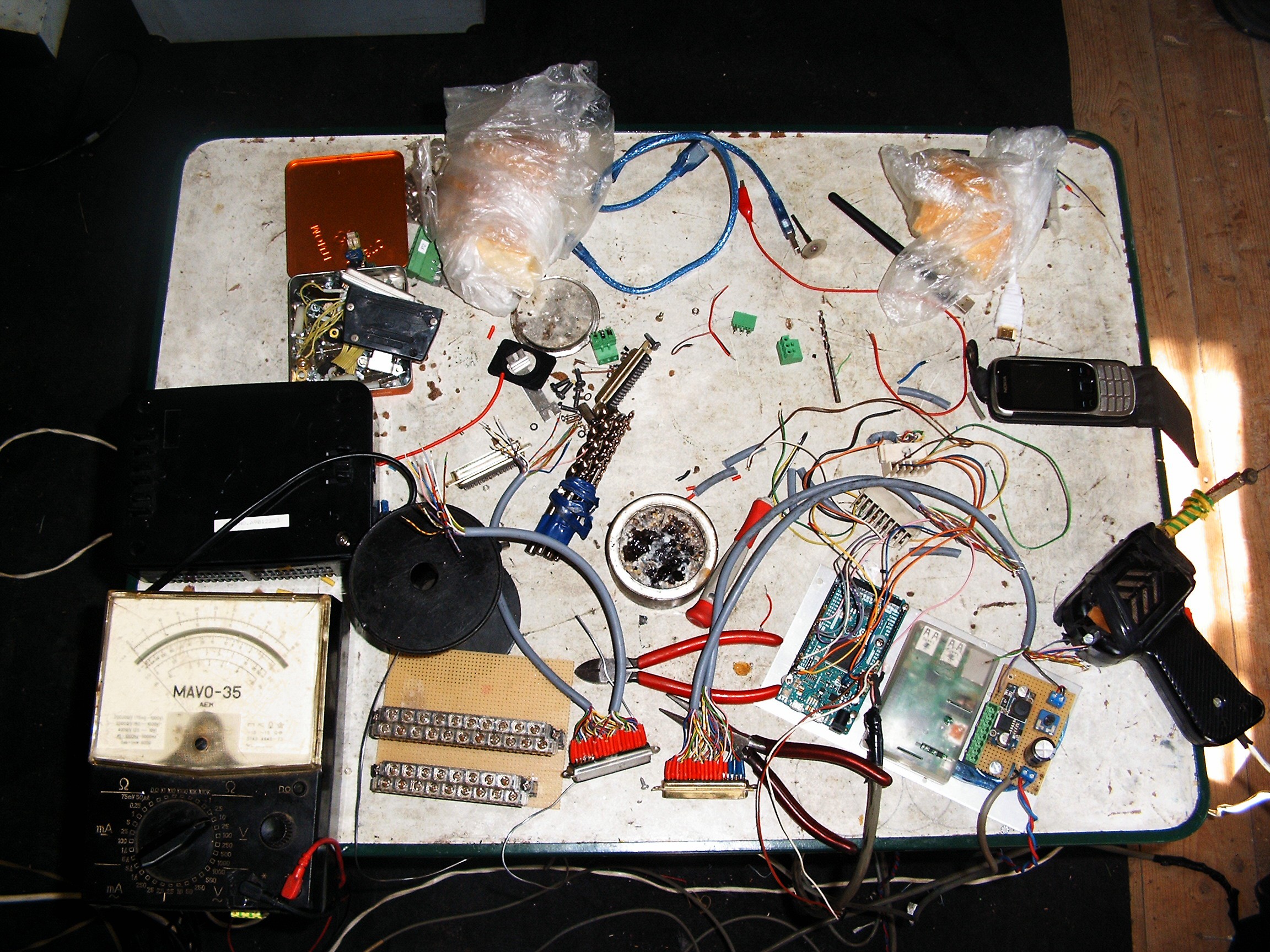
Left side - my old analog meter. Above it - black box - 12V/5A power supply.The yellow PCB with those two connectors - the future junction box where all the sensors will be connected.
![]()
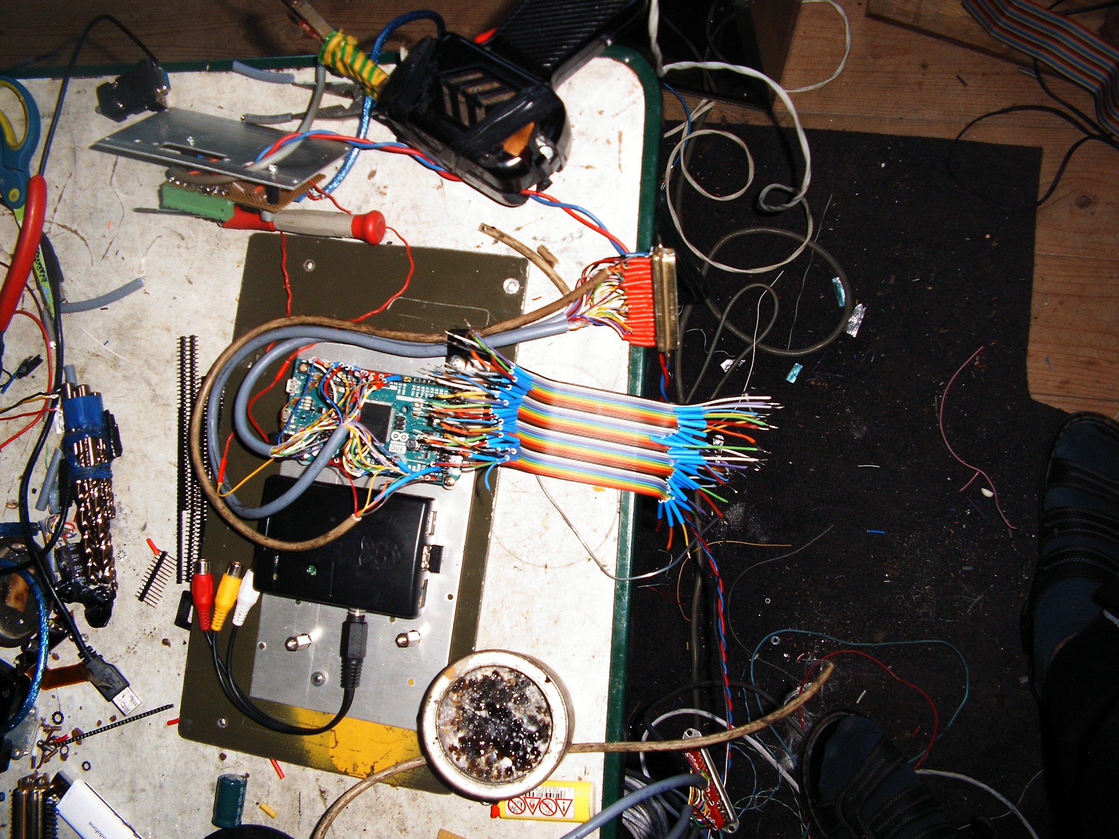
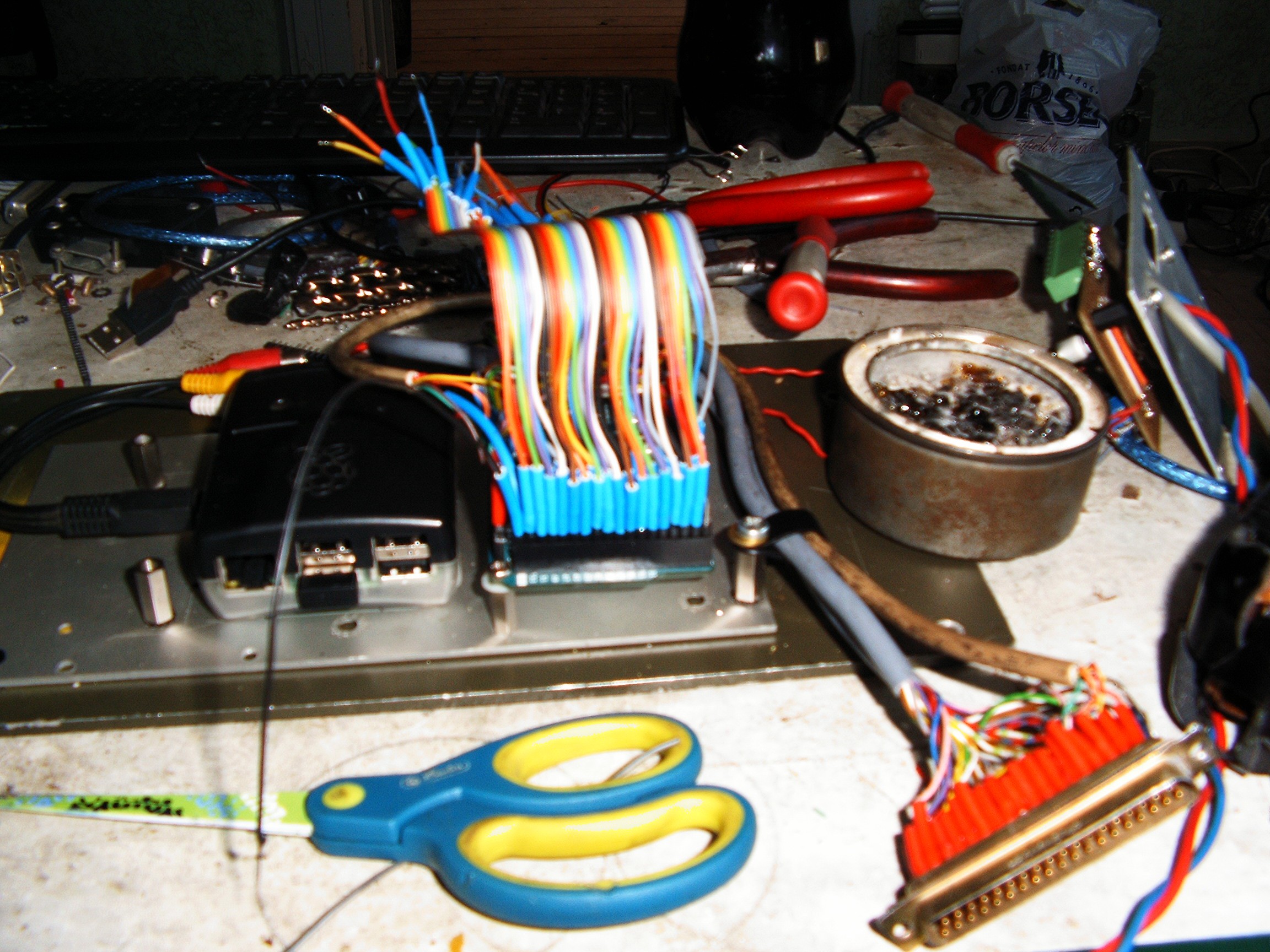
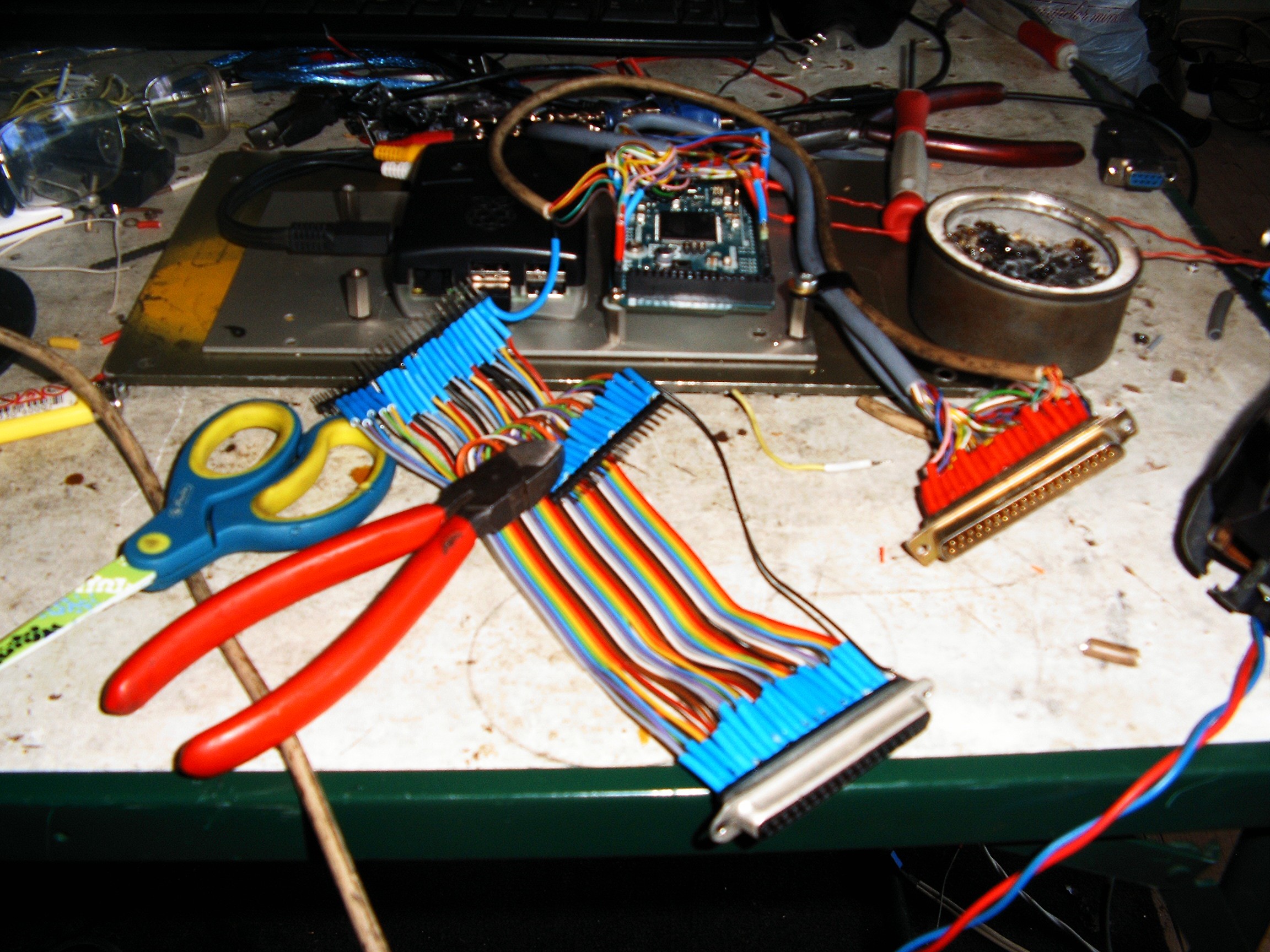
They say "they don't build them like they used to". Building retro equipment also needs special ingredients, such as old-school building style, old-school hacking and old-school optimism. Those DB37 connectors had special care for every single wire - soldering protection against vibrations and cable breaking with normal cable coating.
![]()
If you dismantle any old computing device from the 60s.....80s, you will find the same arrangements. Each connection is treated carefully. It takes a lot of time to finish but it lasts for many life times. That is why all those huge monsters costed millions of dollars. Half of that price was the high quality manufacturing. Show me a modern equipment today that follows those old rules - except army issued devices.
![]()
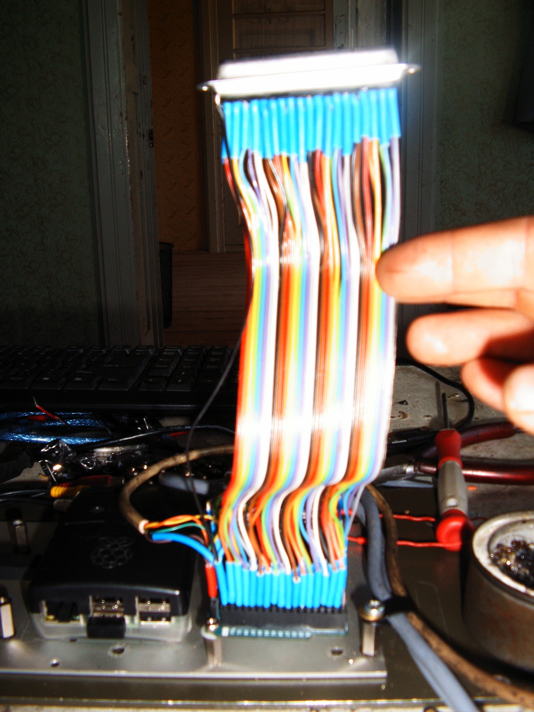
Every single wire has the protection inserted.
One hour later...
![]()
...Arduino ports 22....54 (sleepy, not remembering properly) are covered.
![]()
And this is the arduino to DB37F adapter.
![]()
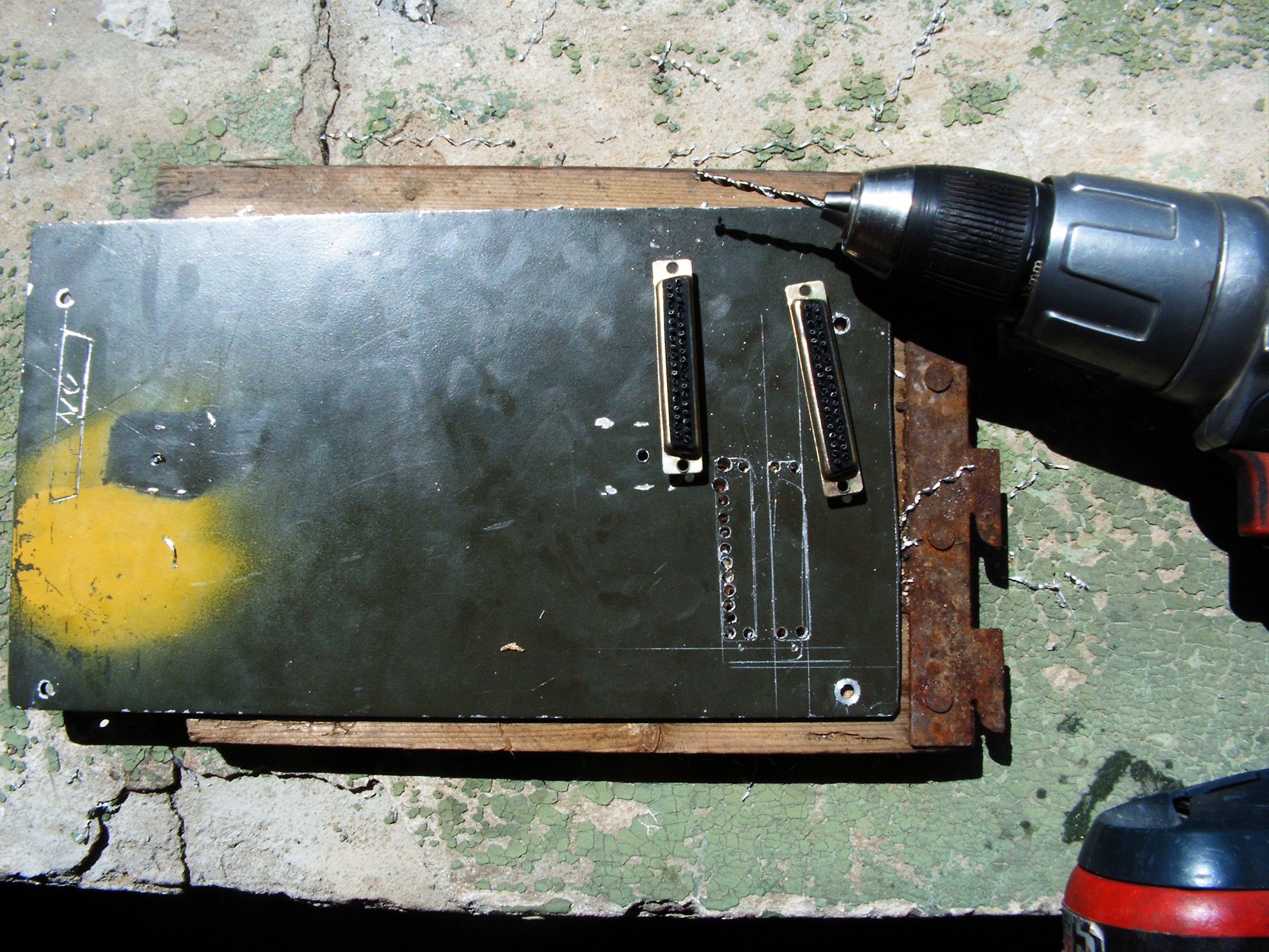
These two DB37 connectors are the Arduino's interface with the outside world. So let's drill some holes in the terminal casing.
![]()
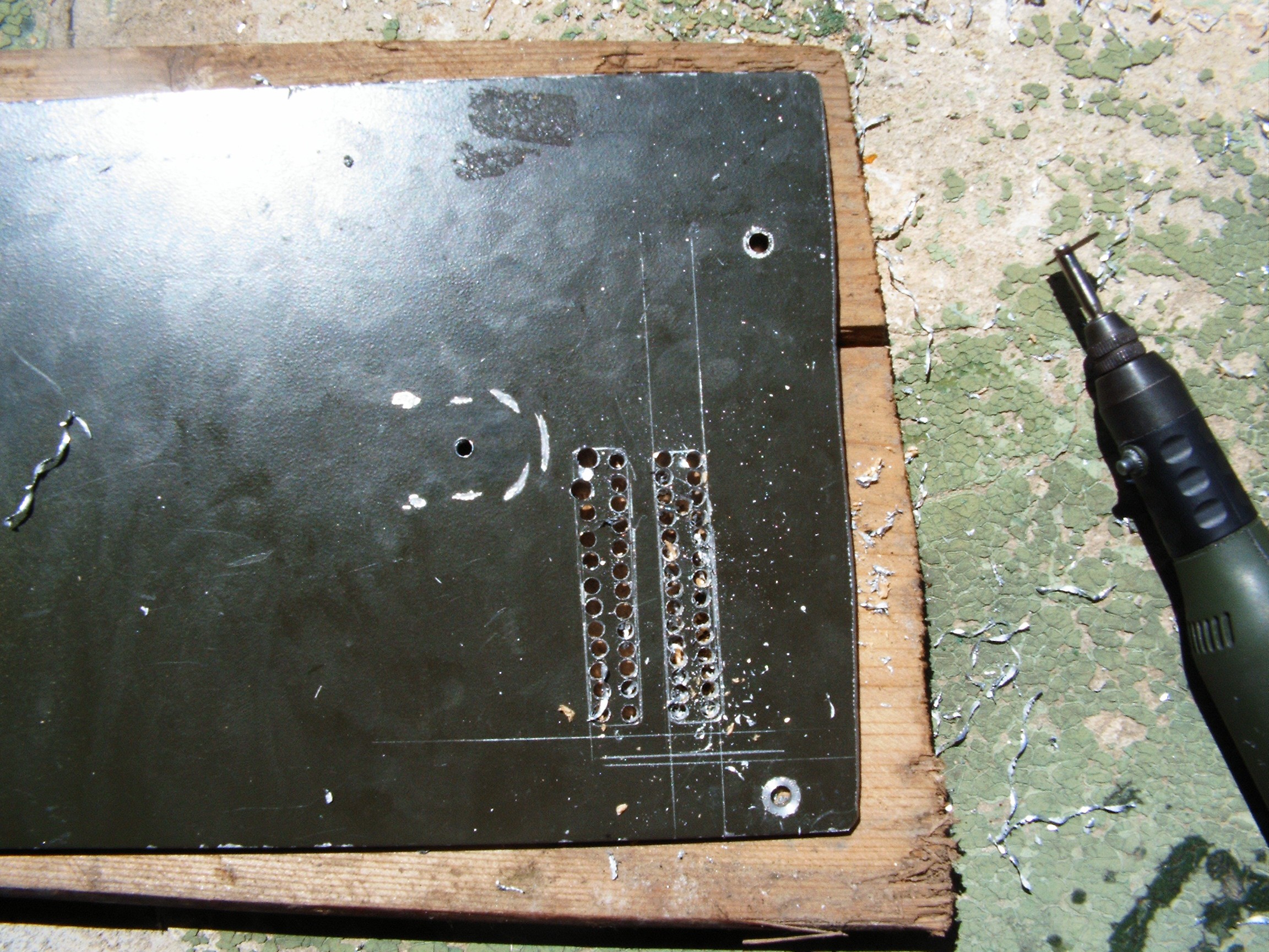
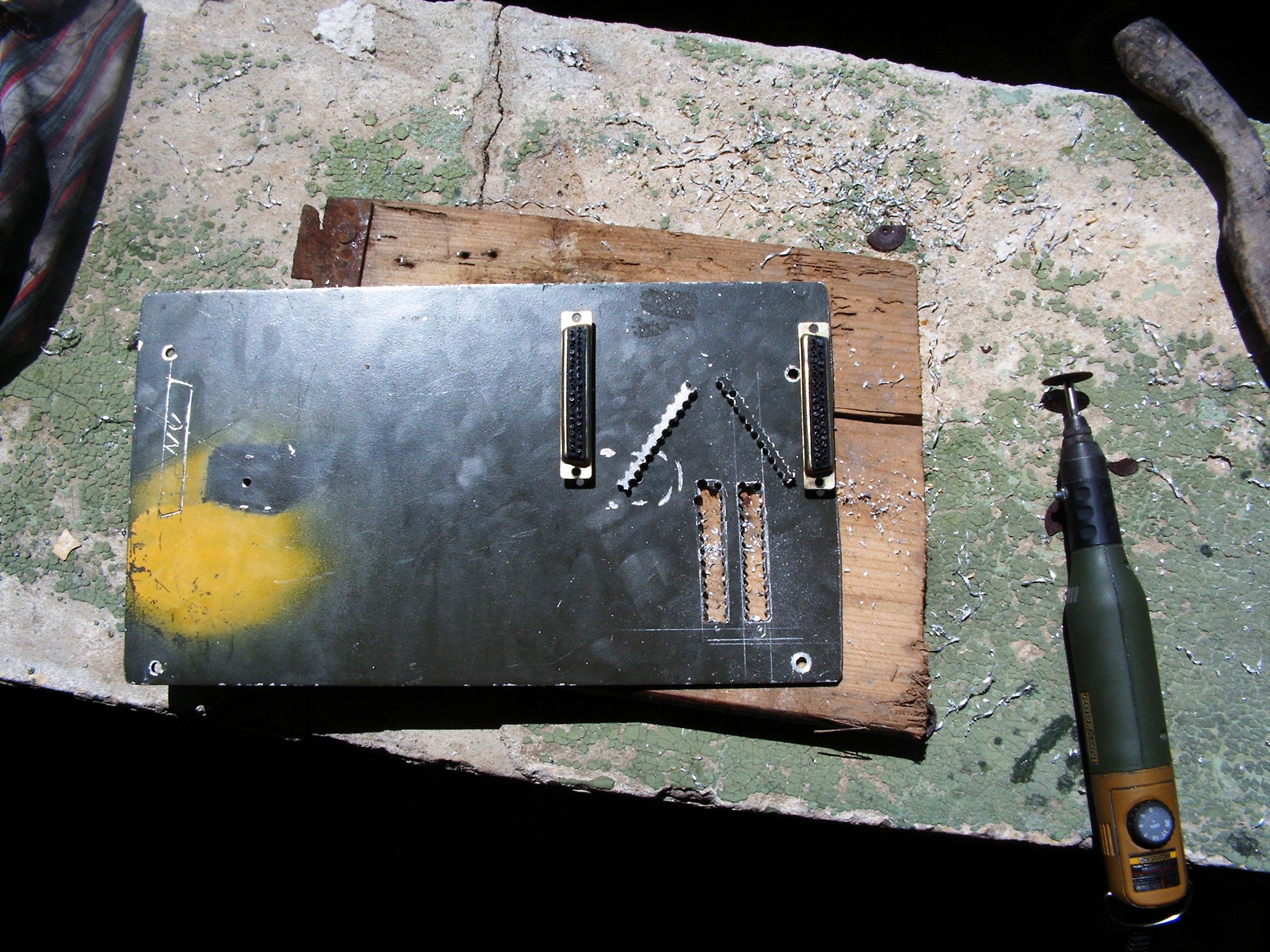
Connectors are in their place. System ready for assembly. Need to cut the DB37 holes, then everything will go straight inside the car.
![]()
this is 5 millimeter thick aluminum sheet. My magic potions do not work in this case, just the patience.
![]()
and many many ceramic disks.
![]()
![]()
![]()
Everything assembled while recharging the batteries for camera.
![]()
The thick white cable connects one of the DB37s from the terminal to the Junction Board on the console. For now there are two sensors connected: gasoline flow sensor and ambient light sensor. Everything else will be connected there through optocouplers or resistive dividers. Attention: arduino due accepts maximum 3.3V inputs.
For now the old gauges are connected. I still have to install all the warning lights.
Unfortunately I am unable to follow @Benchoff's suggestion - satellite navigation. NavIT should work but it does not compile under FreeBSD. And I am awayting for user name confirmation on their forum for almost a month - nobody bothered to answer.
Next log: rebuilding gauges and dials.
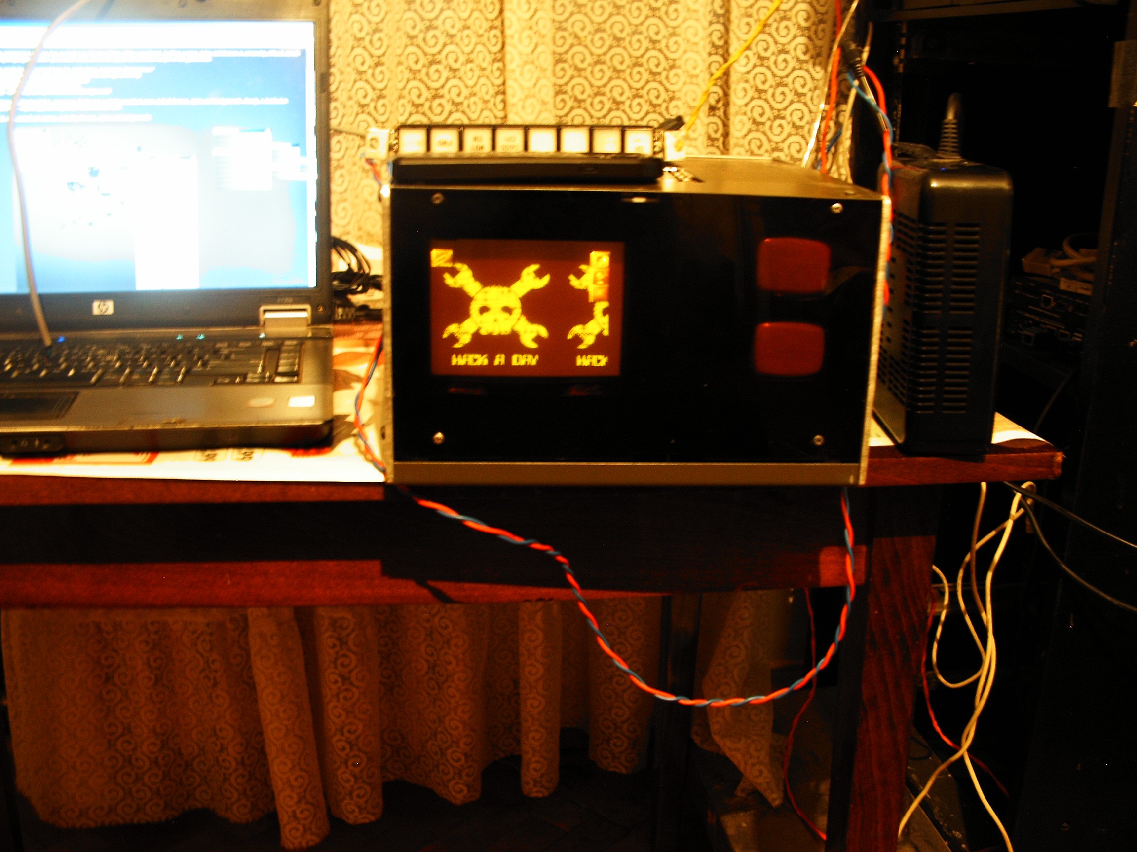
In the mean time, surprise!!!
![]()
WindowMaker with HaD logo as background picture. The only image viewer I could find faster.
Next time when I open the terminal cover, I wish to display the HaD logo also on those two tiny oscilloscope CRTs.
Software is now work in progress. I only have a diagnosis table showing all the monitored parameters. Automobile diagram is desired, but I am still limited by FreeBSD capabilities and I'm not good at Linux.
[END OF TRANSMISSION]
______________________________________
kernel panic: improbability coefficient below zero
-
Radiation Detection System
05/29/2016 at 23:31 • 0 commentsI planned to use one of my older projects, a PIC16F84-based radiation detector.
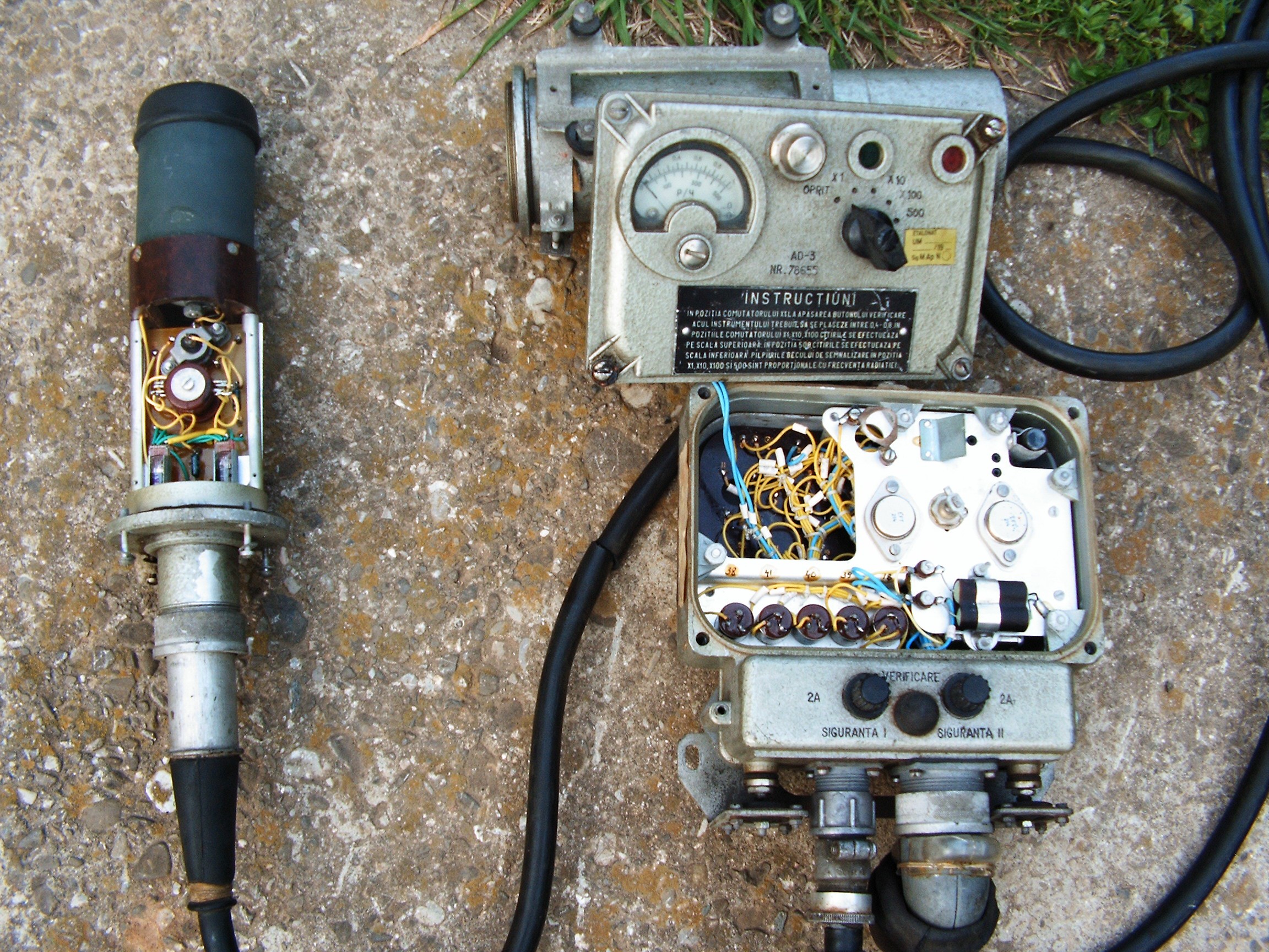
Until I found this army-issued monster:
![]()
Left side, top: green detection tube (unknown code) plus vacuum-tube-based amplifier.
Right-side (top) meter + dial, and some germanium-based transistors for high voltage connector.
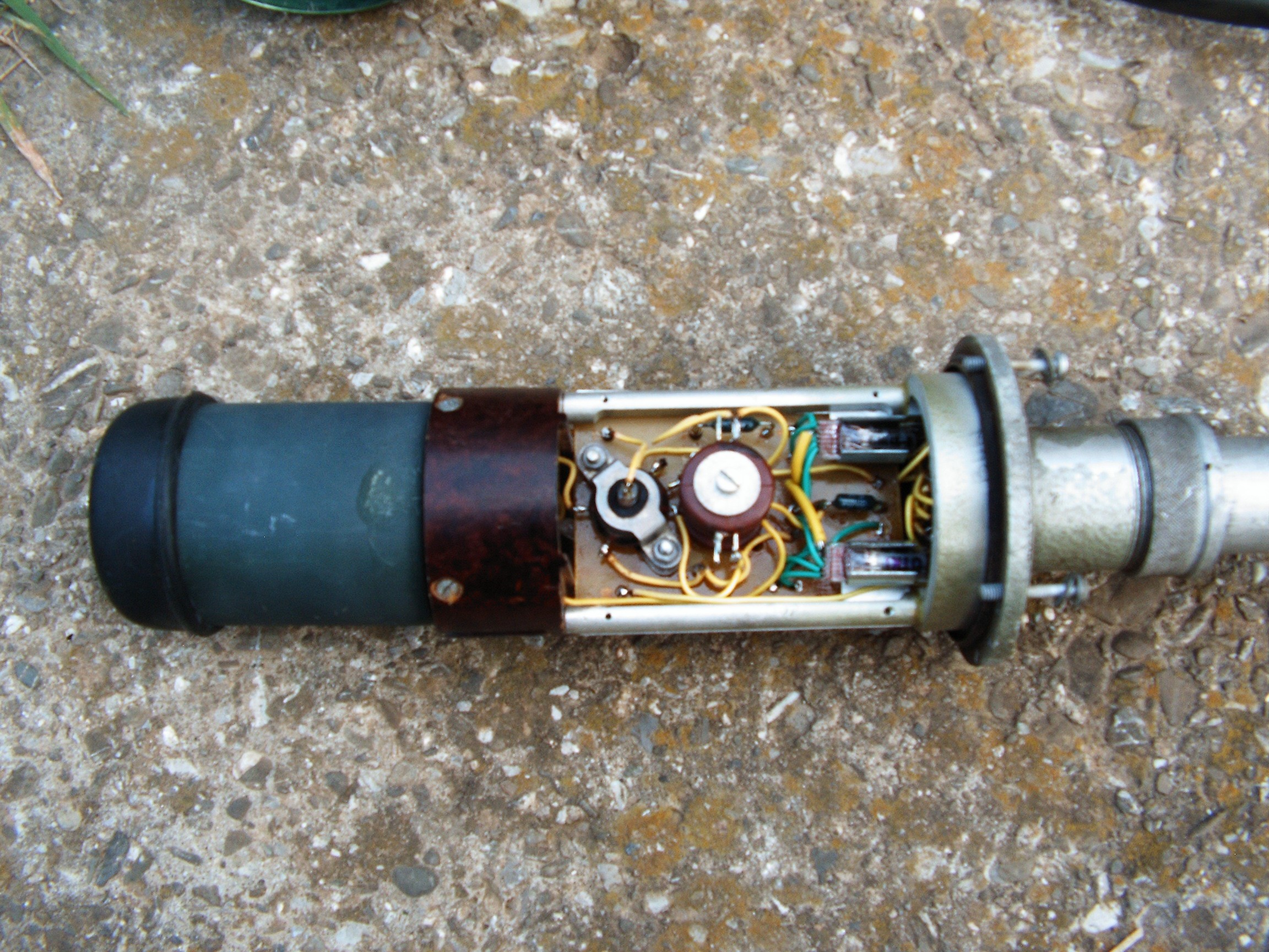
Detector:
![]() from left: detection tube, then a 6J1J lateral contacts, pass-through-hole pentode, and two 6J45B subminiature tubes. There is also a long long 4.6GigaOhms resistor, I will try to make a closer photo of that.
from left: detection tube, then a 6J1J lateral contacts, pass-through-hole pentode, and two 6J45B subminiature tubes. There is also a long long 4.6GigaOhms resistor, I will try to make a closer photo of that. Detector does not work with cover removed, it is too sensitive.
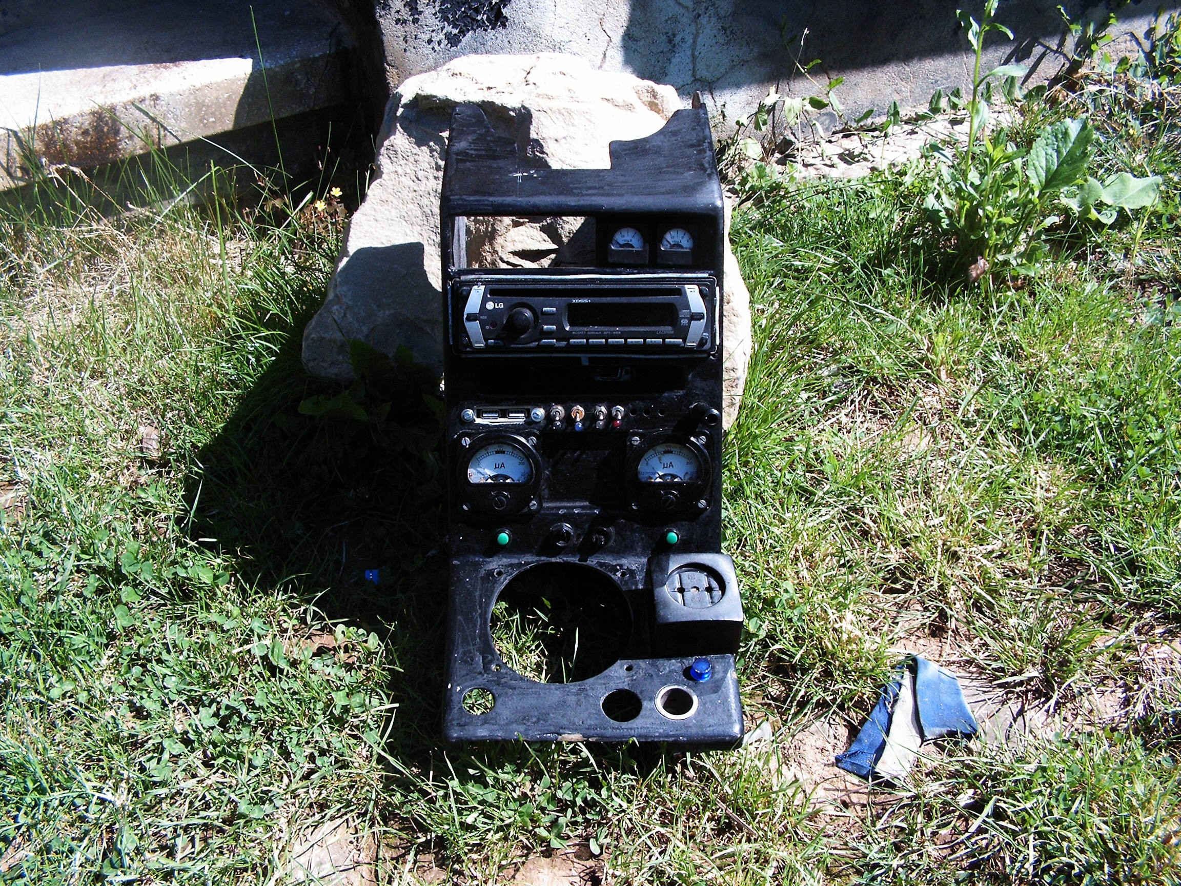
This detector will stay under the car to monitor the radiation while driving and log the data - only when needed. Display panel stays in the car - under the console for now:
![]()
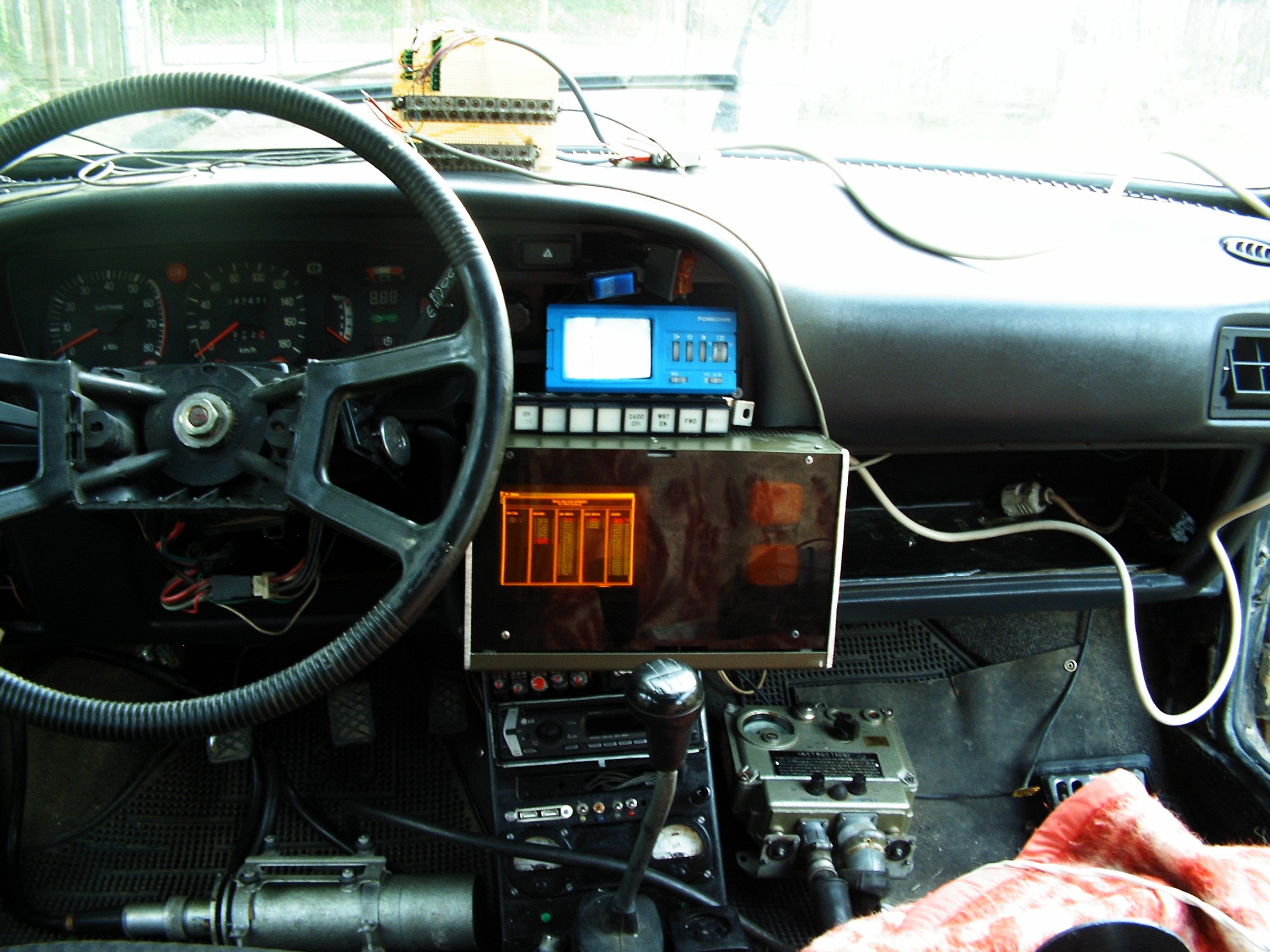
Radiation level is also displayed on the diagnosis screen - second column, third from bottom:
Next log will show the building process of the tiny terminal.![]()
[END OF TRANSMISSION]
______________________________________
kernel panic: improbability coefficient below zero
-
Vacuum Tube Sound System (II) - final stage
05/29/2016 at 23:12 • 0 commentsI had to modify the final stage. It takes too long to build the audio output transformers - since the first round reward took some time to arrive - so while surfing on the HackChat, one post of @Benchoff sparked me an idea...
- Input stage and equalizer stays the same;
- my vacuum-tube-modified sound card stays away for now;
- final stage rebuilt with some usual and some not-so-usual components.
Ingredients:
- 2 x Nokia classic chargers, transformer-based, 5Volts output;
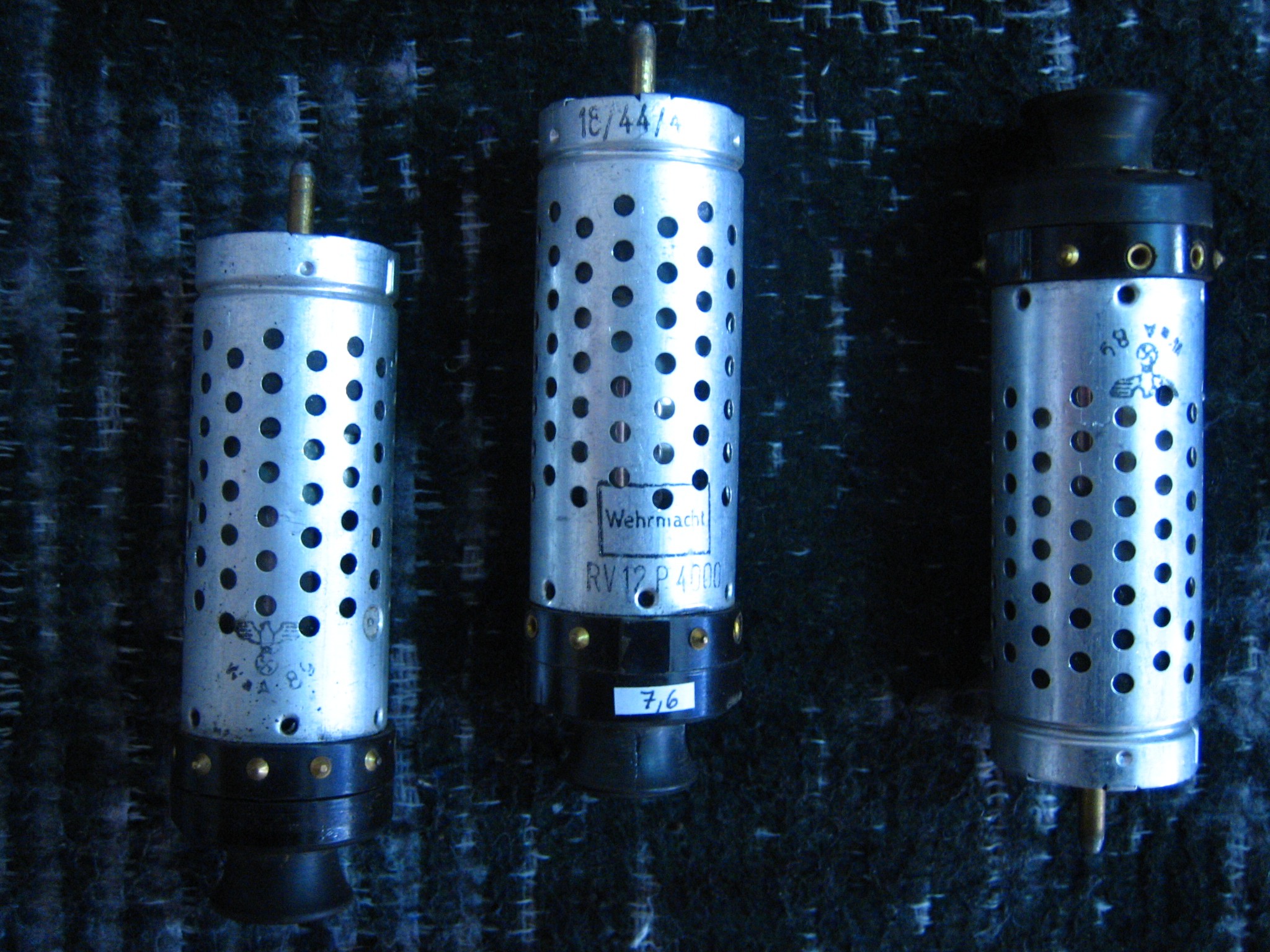
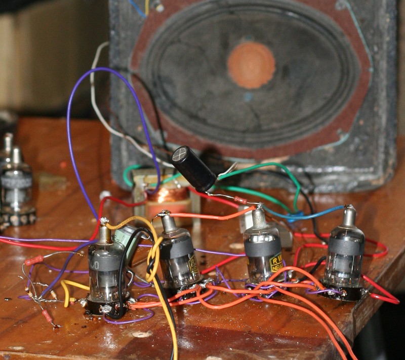
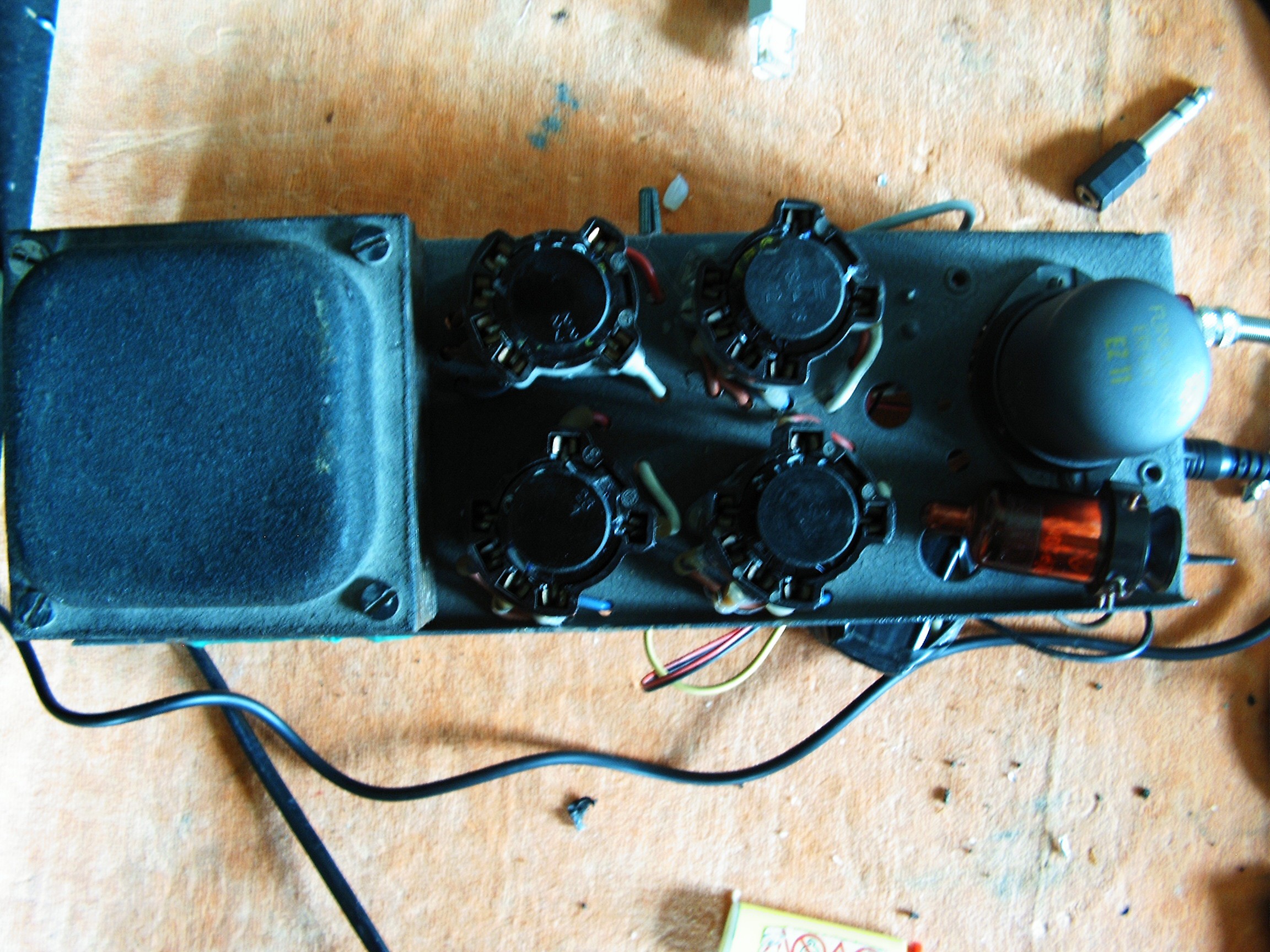
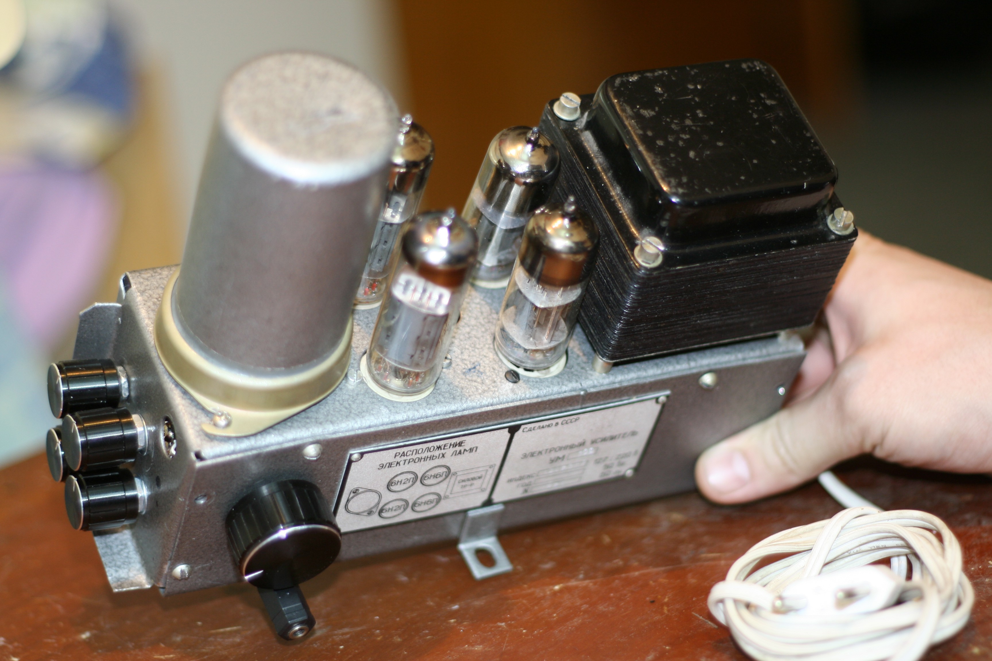
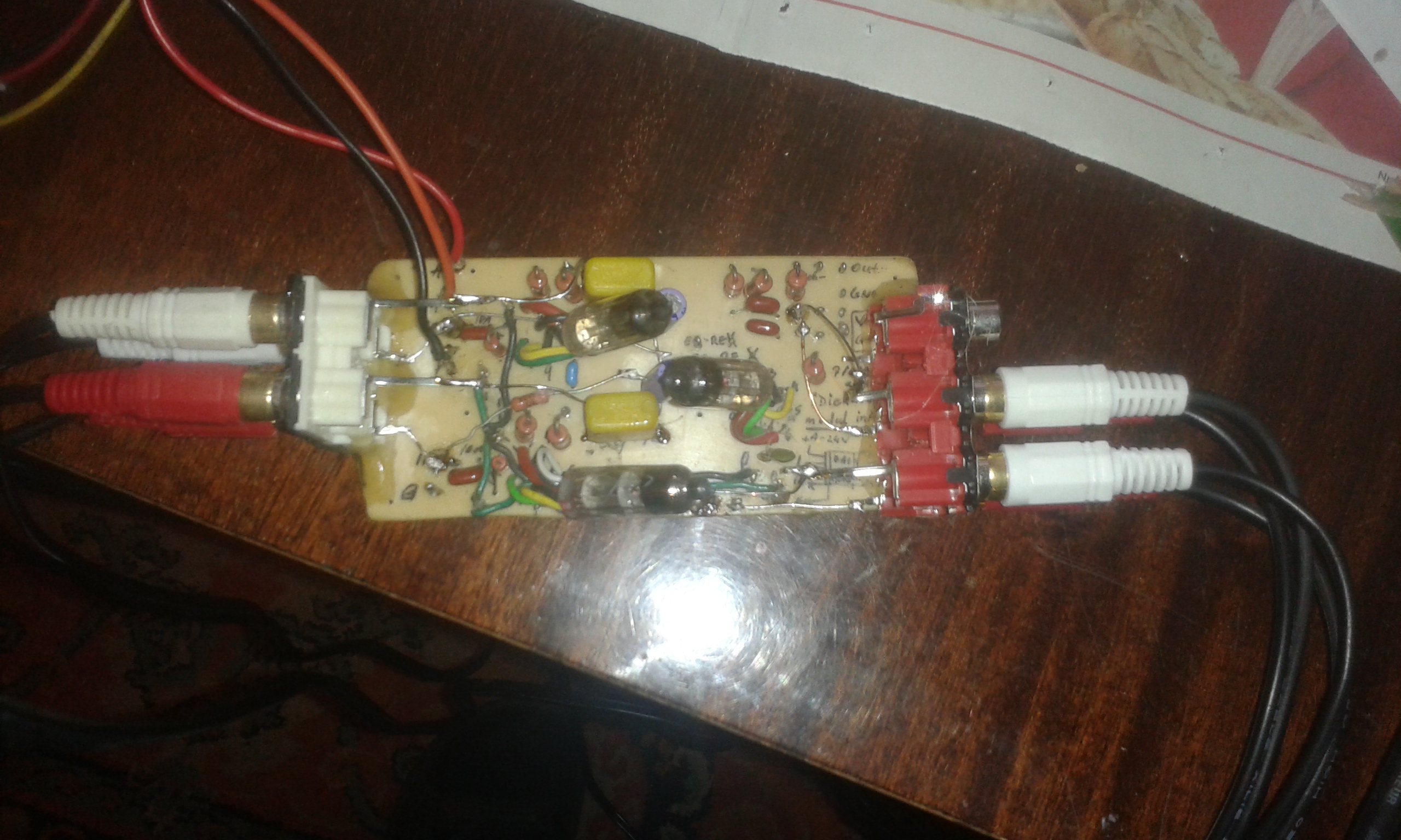
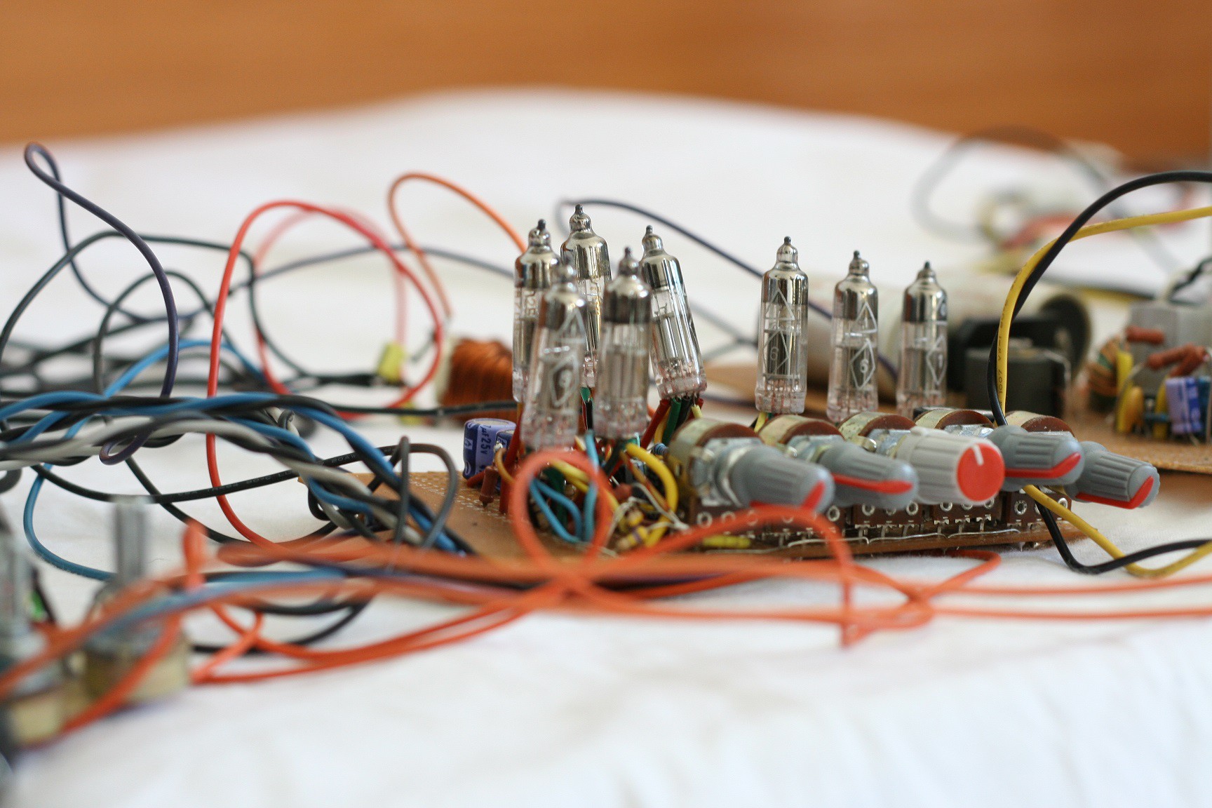
- 4 x RV12P2000 (or RV12P4000?) Wehrmacht-issued medium power pentode vacuum tubes, made in 1940s. Only 3 pieces RV12P4000 shown in the picture. On top of the middle tube it is written "18/44" - manufactured during week 18th of the year 1944. On bottom it says "Wehrmacht's property";
![]()
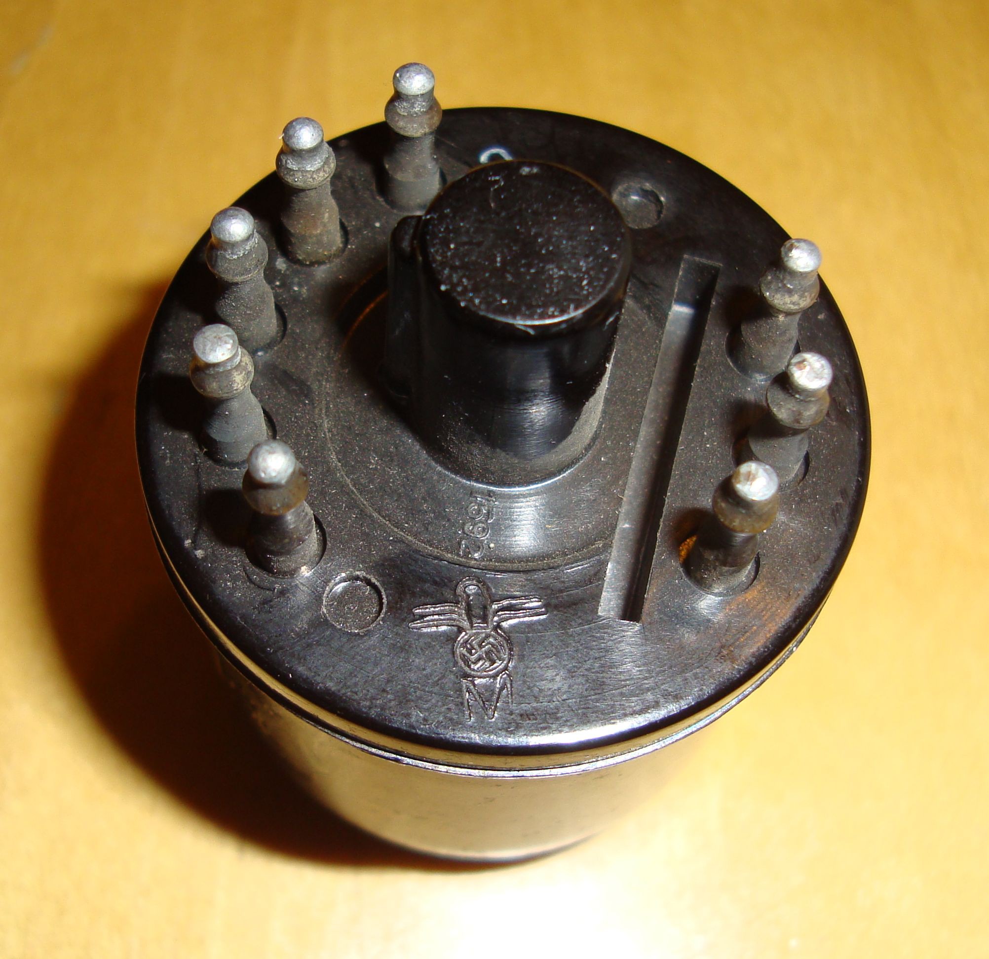
- 2x EZ11 Wehrmacht-issued rectifying double-diode, metallic enclosure, made also in the 40s;
- sockets for all the above mentioned vacuum tubes;![]()
- 2 x volume control multi-turn resistors;
- 2 x high voltage transformers;
- a bunch of resistors and capacitors;
- 2 x enclosures beautifully painted - recycled from trash dumpsters;
- 2 x enclosures from switching vibrators;
- my schematic.
First we prepare the audio output transformers. Those Nokia transformers will get their cores dismantled into the basic components: the "E" sheets and "I" sheets. These will be reinstalled separated, like this: first the "E"s, then a piece of paper 2mm thick and boiled in automobile engine lubricating oil, then the "I"s. We need to do that to keep the magnetic field opened in the core, or else we will lose power from the pentode stages and also wear the vacuum tubes in time.
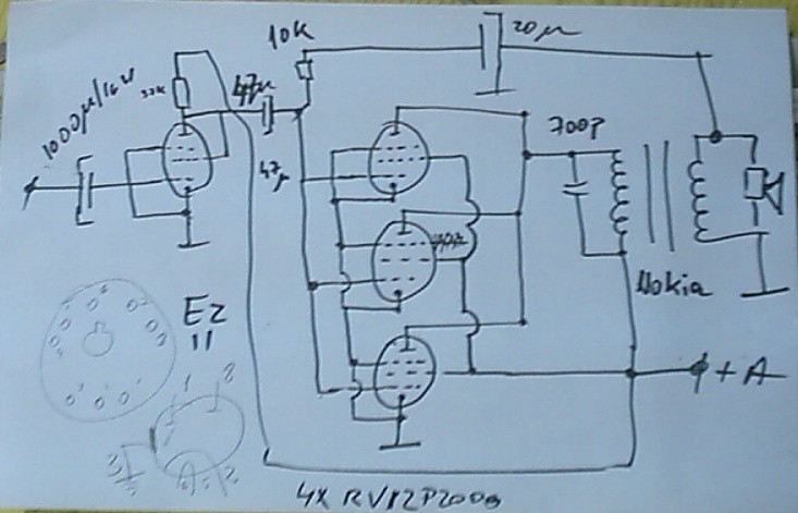
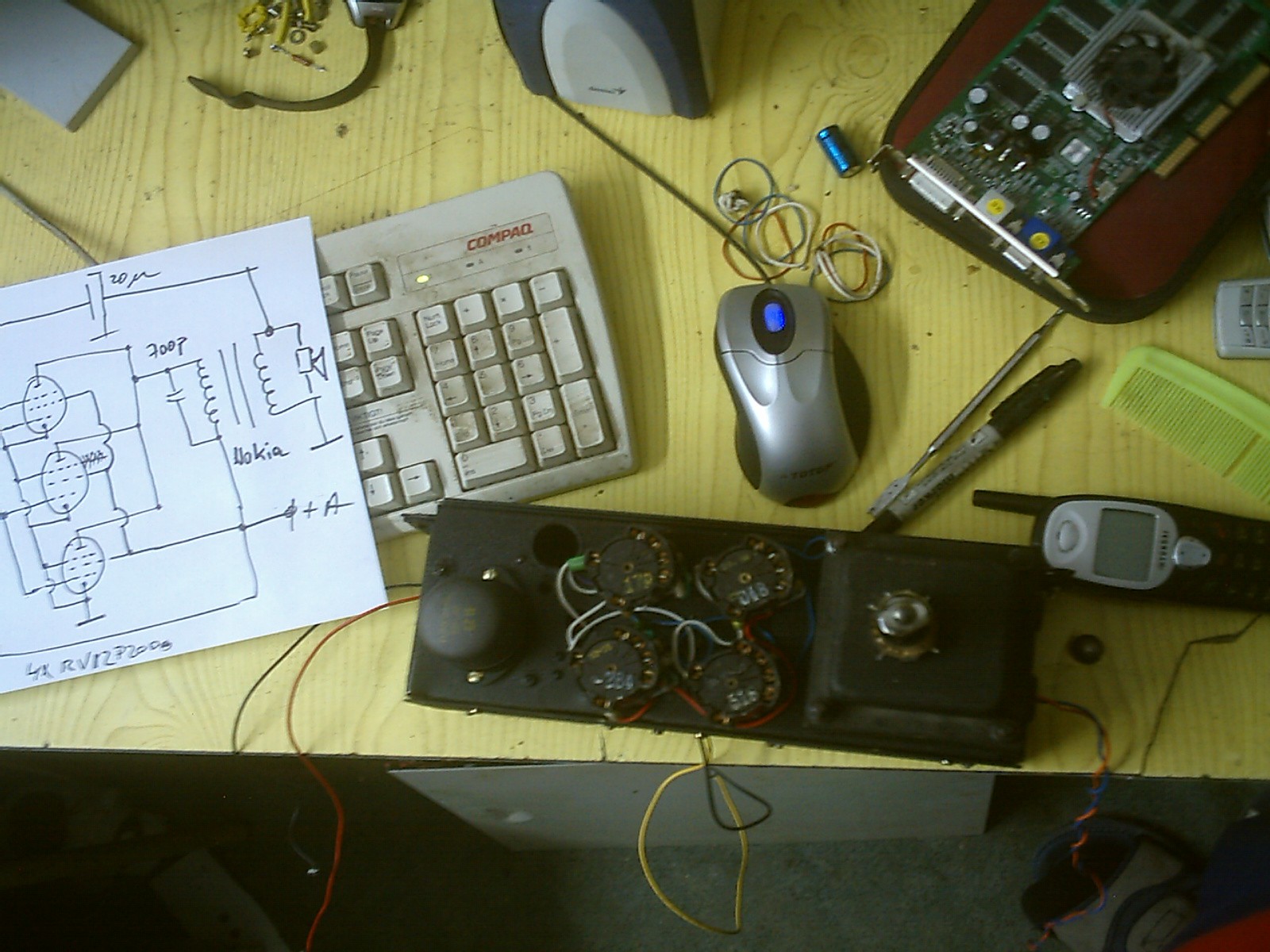
Schematic, hand-drawn as usual:
![]()
The audio signals input goes through a 1000uF/16V capacitors, then in the first grid of the first RV12P* tube - which in this case is configured as a triode (G2 connected to cathode). Signal separation from anode is made with a 47uF capacitor, and the feedback loop is done through 10k-20uF group. The other 3 tubes are connected in pentode configuration in parallel. 700pF capacitor needed to cut down in-tube electric discharges in case of high input level. Also smooths the sound. Nokia transformer is connected with 220V primary stage between anodes and +A (around +196V). Secondary wiring (5V) goes to speaker. Rectifier stage is the simplest half-wave rectifier- classic schematics are on the internet.
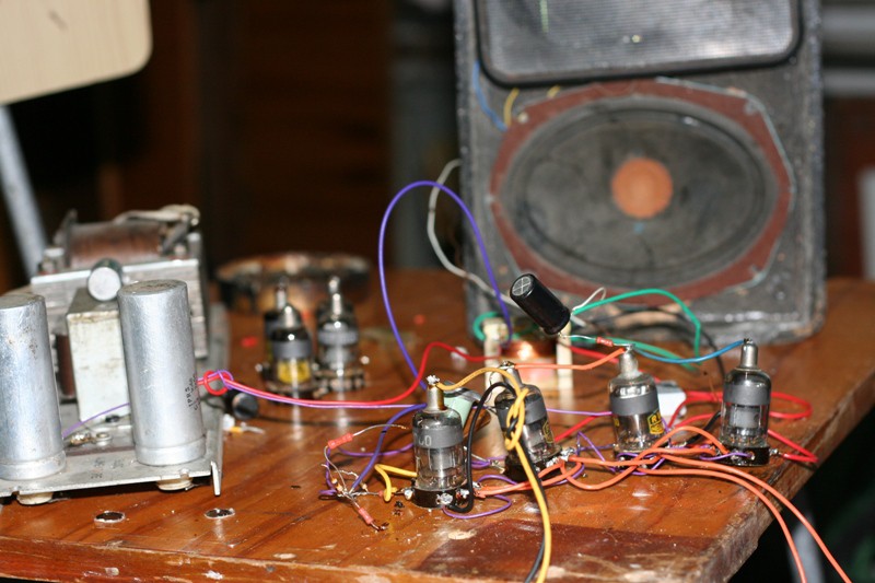
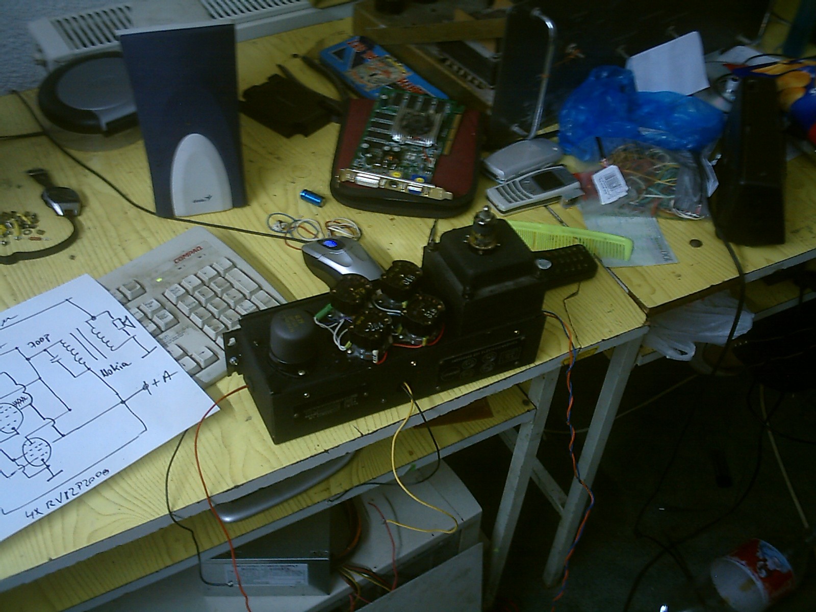
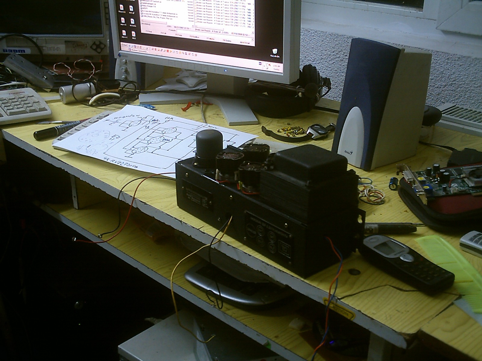
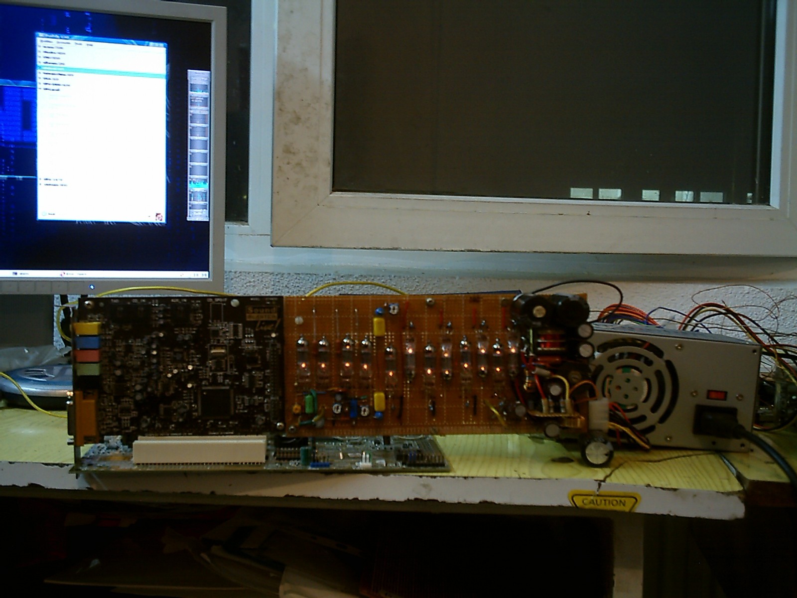
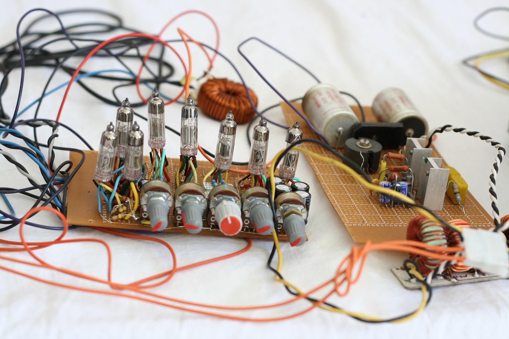
The built final stages look like this:
![]()
"Naked" vacuum tubes. Not connected inside sockets.
![]()
This, my dear friends, is Romanian Wooden Breadboard on Steroids, powered by +200 volts. This is serious stuff, if you start working at this level you will understand that five volts is for pussies. This is not a game, it is dangerous and requires a lot of attention. Not for people with heart problems. Five volts only - that's simple child play.
Nokia transformer in the background. The sound is GREAT, even if it comes from that trashed speaker. The sound coming from an old reel to reel tape player is like an erotic wet dream for the ears.
Unfortunately I could not find any RV12P4000 sockets, so I'm stuck with the smaller tubes.
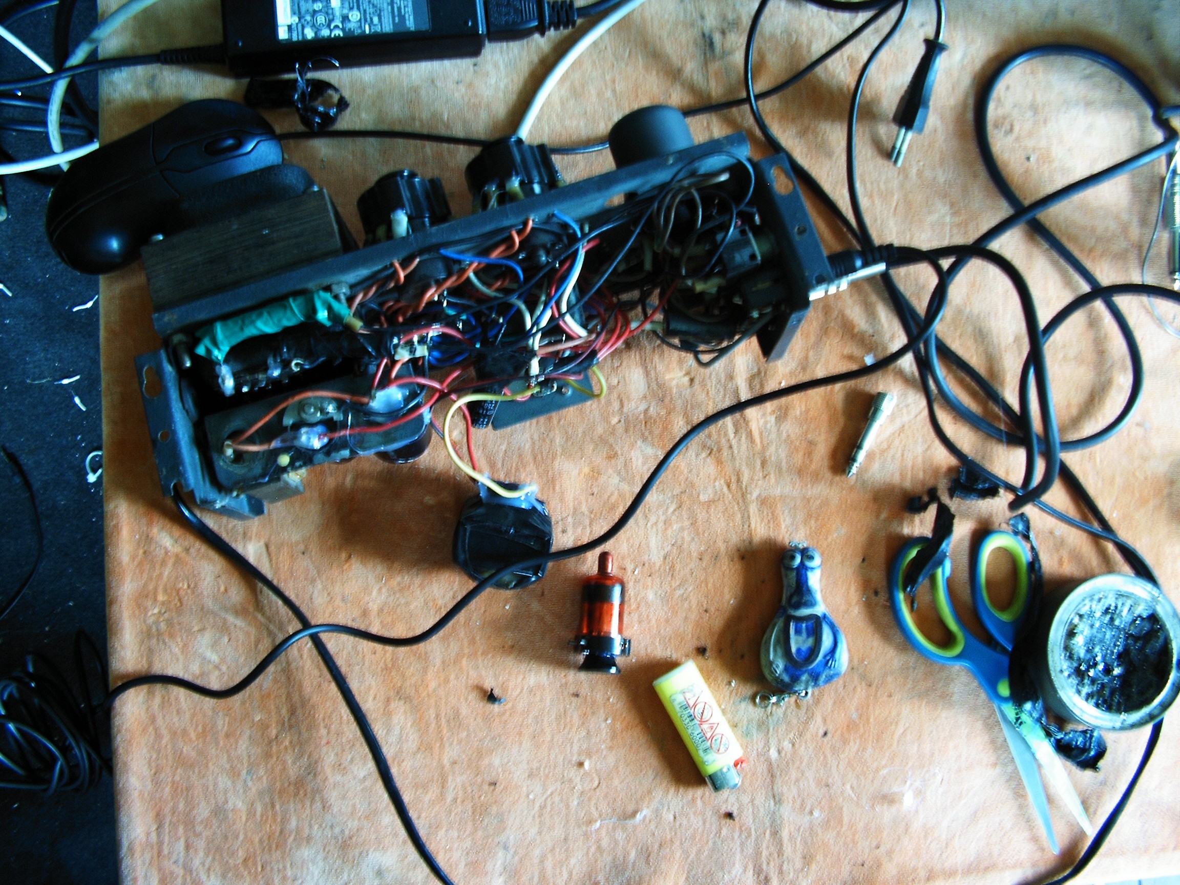
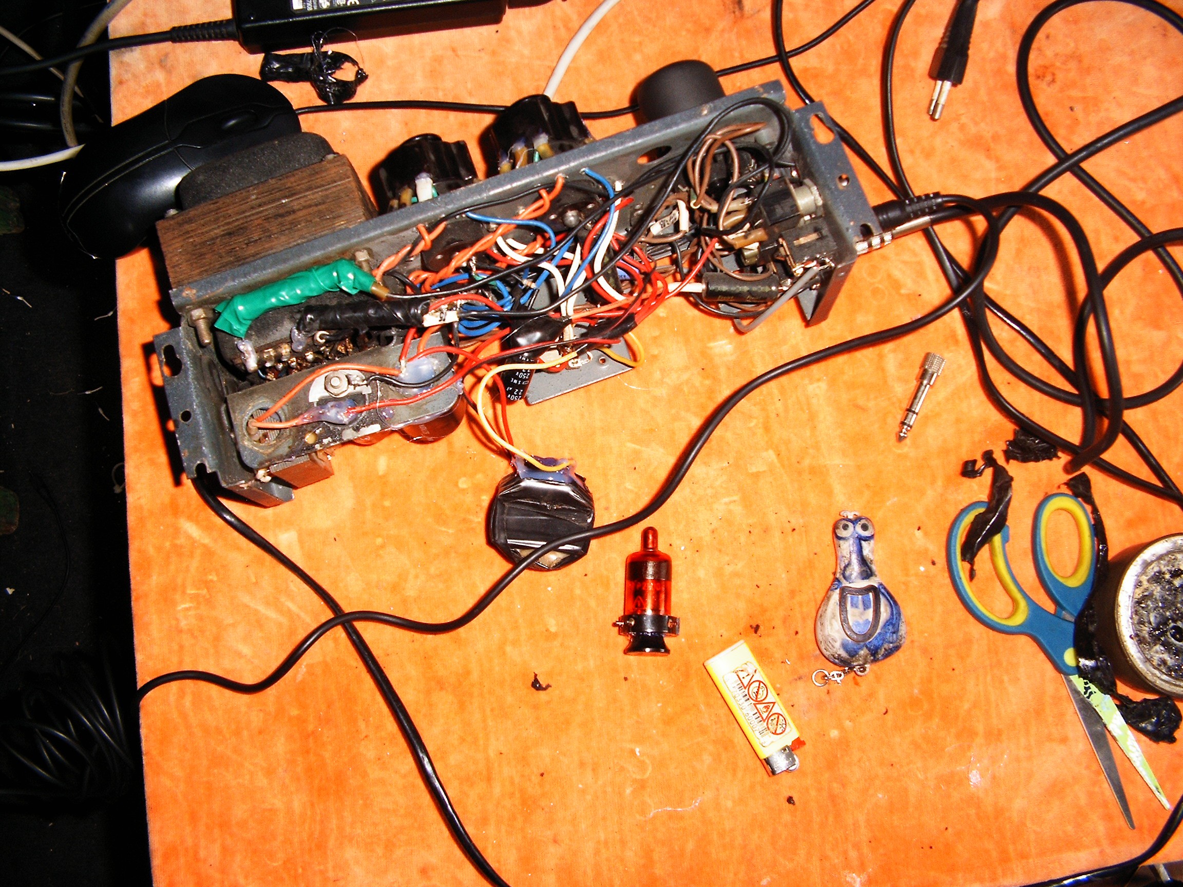
Amplifier rebuilt in some random case I found in the trash dump...
![]()
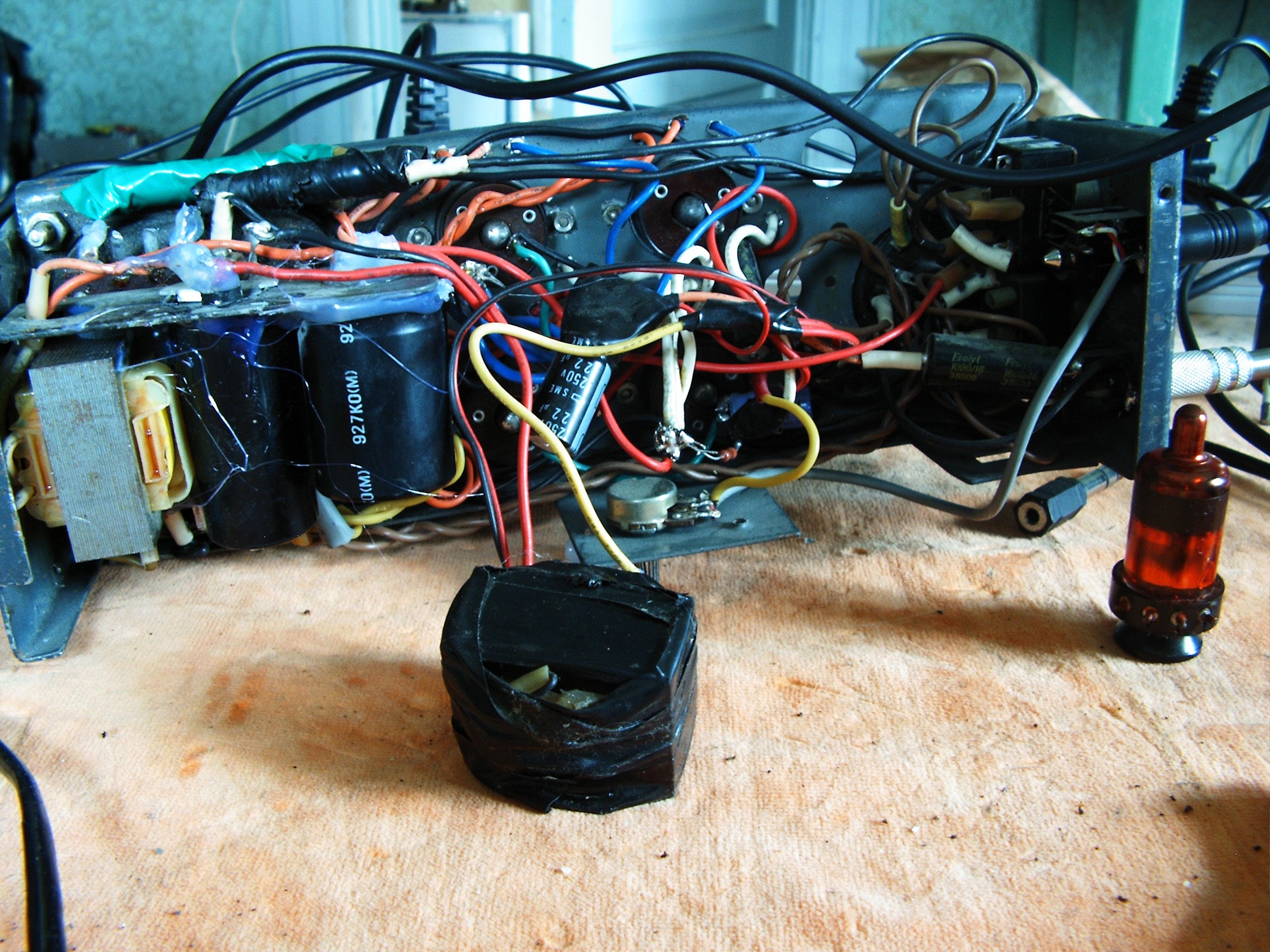
![]()
![]()
![]()
![]()
Inside sockets those tubes are connected upside down. There's a tube placed on the transformer as a reference.
![]()
This is the left channel.
![]()
Now the right channel:
![]()
![]()
Yes, the enclosures look the same. They are from some old automatic graphing devices which painted some lines using a pen and a mobile arm.
RV12P2000 was very very popular from the 30s until the 60th. Russians took it, changed the socket and glass enclosure and re-named it 12J1L. 12 means 12V filament, J means pentode, series 1, L means glass-aluminium enclosure. Then more variations were made: 2J27L, 6J6 (glass-steel enclosure), 6J1P (EL95), 6J1B (subminiature). And many many other "J" variations.
Instead they were unable to copy RV12P4000, which has a huge amplifying factor.
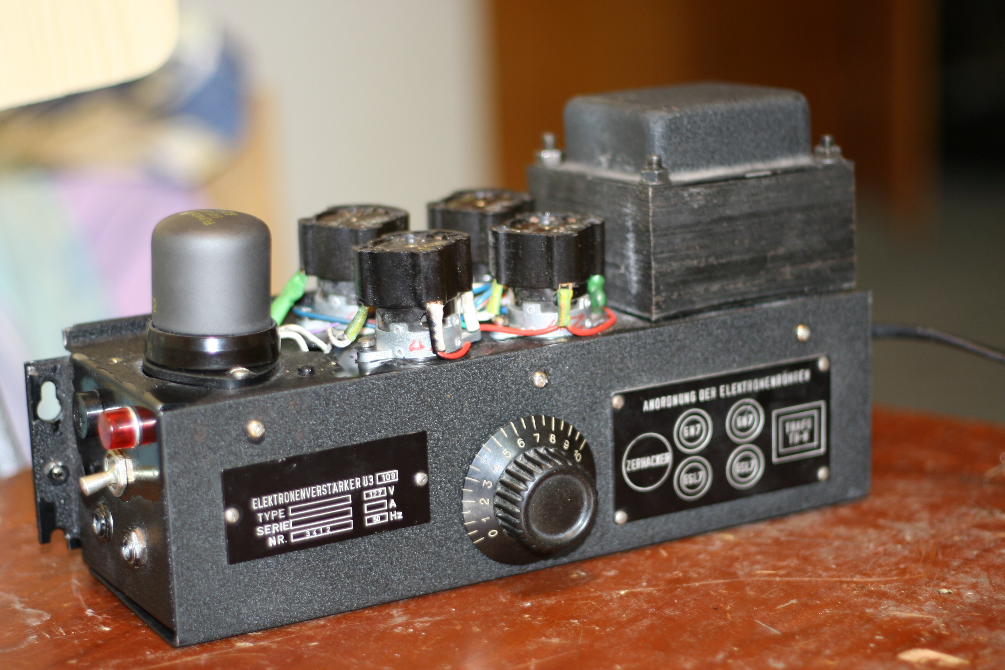
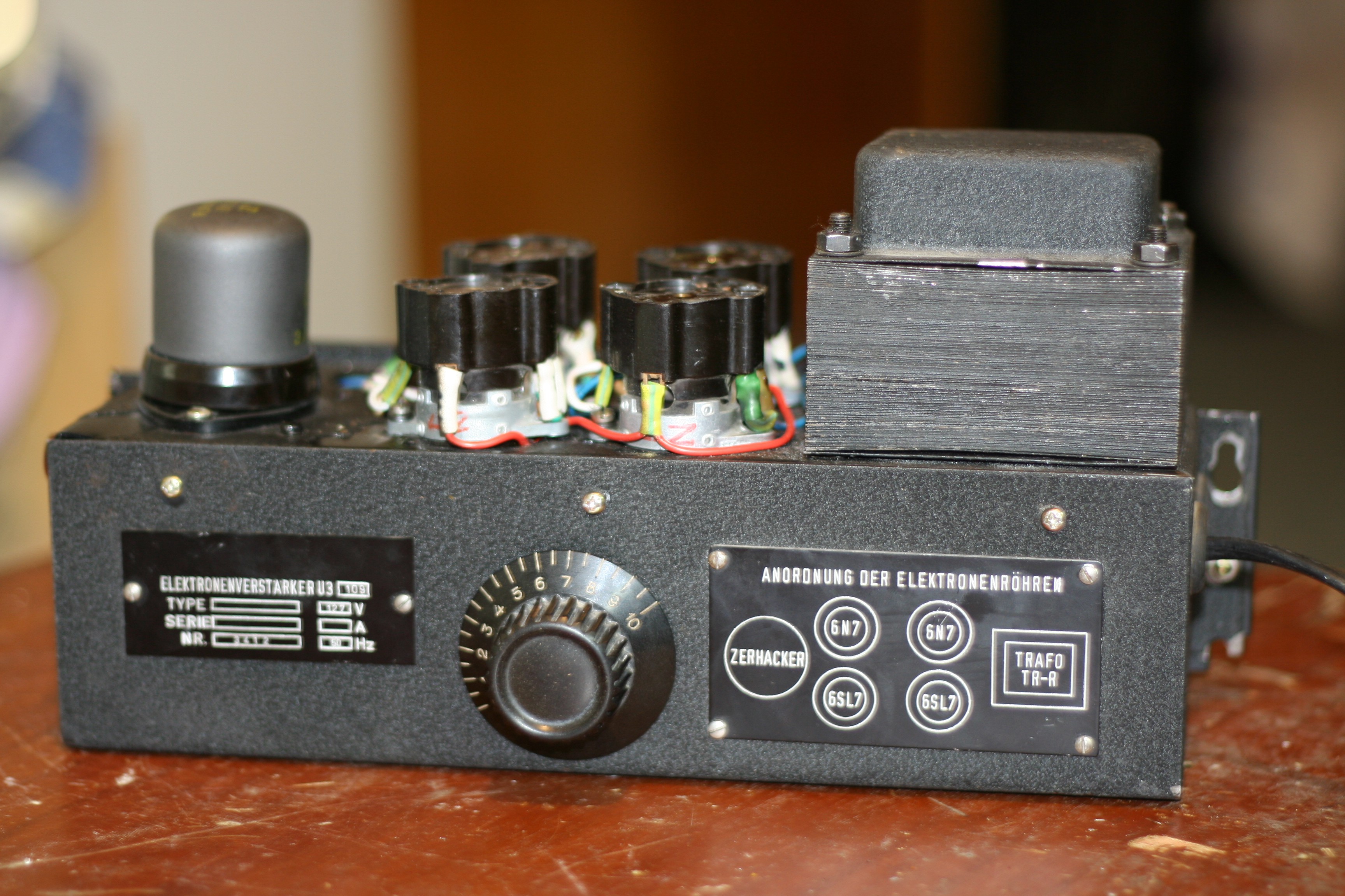
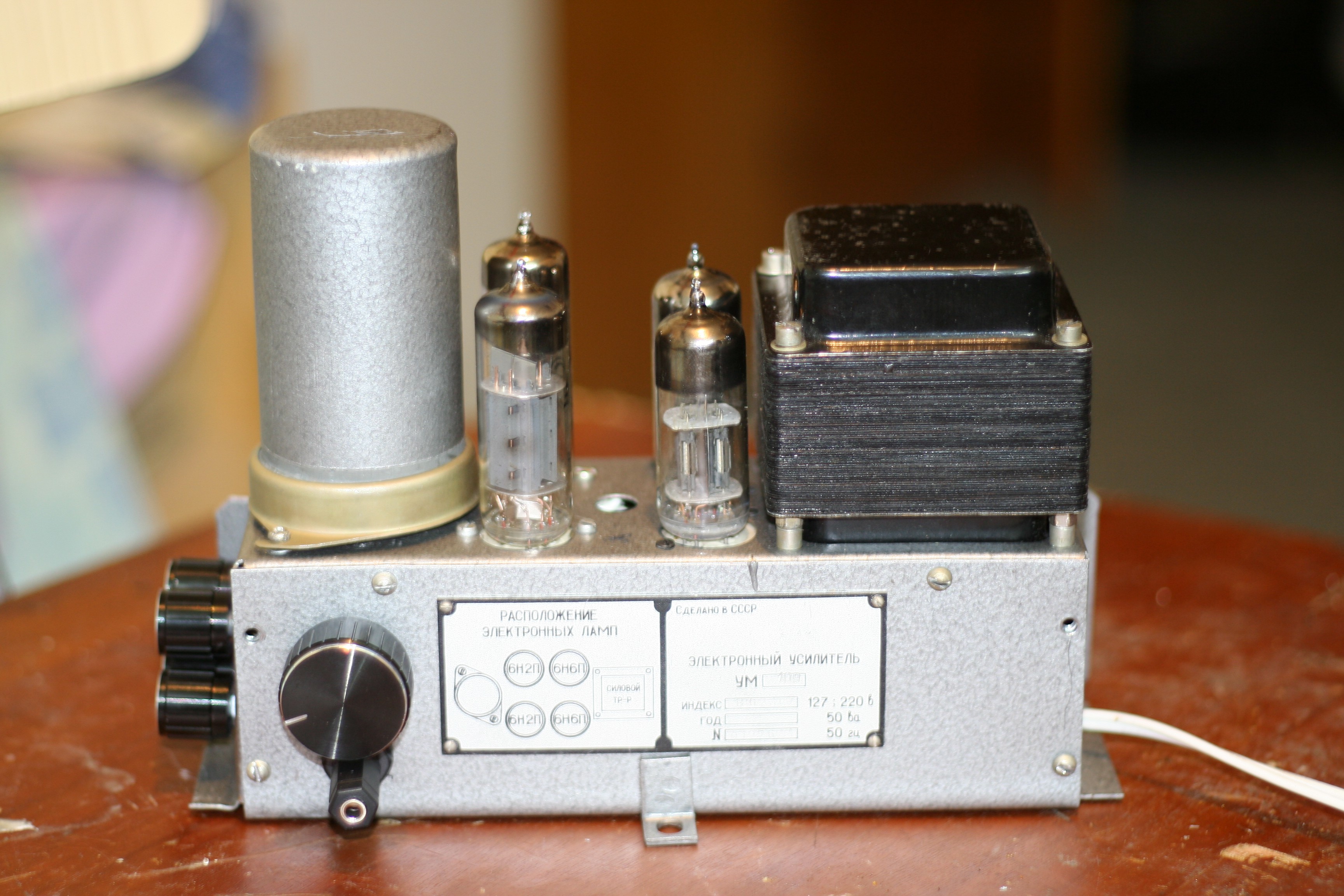
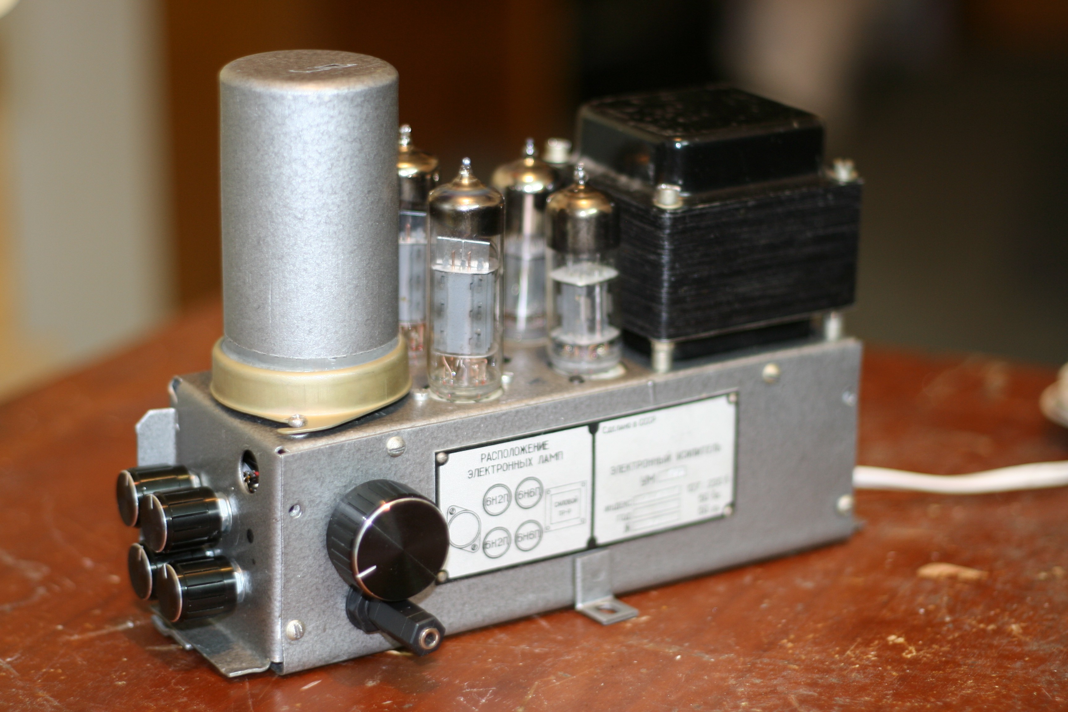
Now, the final stage re-built using Soviet Union tubes: 6H6P triodes (first valve in schematic) and 6F3P (ECL84) instead of the other three pentodes in parallel. This is a double-amp, meaning it is already stereo. Unfortunately the transformer is unable to handle it, it is too small. The enclosure is from the same type of graphing device - but Russian made. Also recovered from trash.
![]()
![]()
![]()
The gray big cylinder metallic enclosure (left side) covers the Nokia transformers.
Again - Soviet Russia vs. Germany but fighting in Audio War. Tests will determine which one is suitable: two German mono amps or one Russian stereo amp.
The winner should fit in the audio system enclosure and will be powered up by the UPS mentioned two logs before:
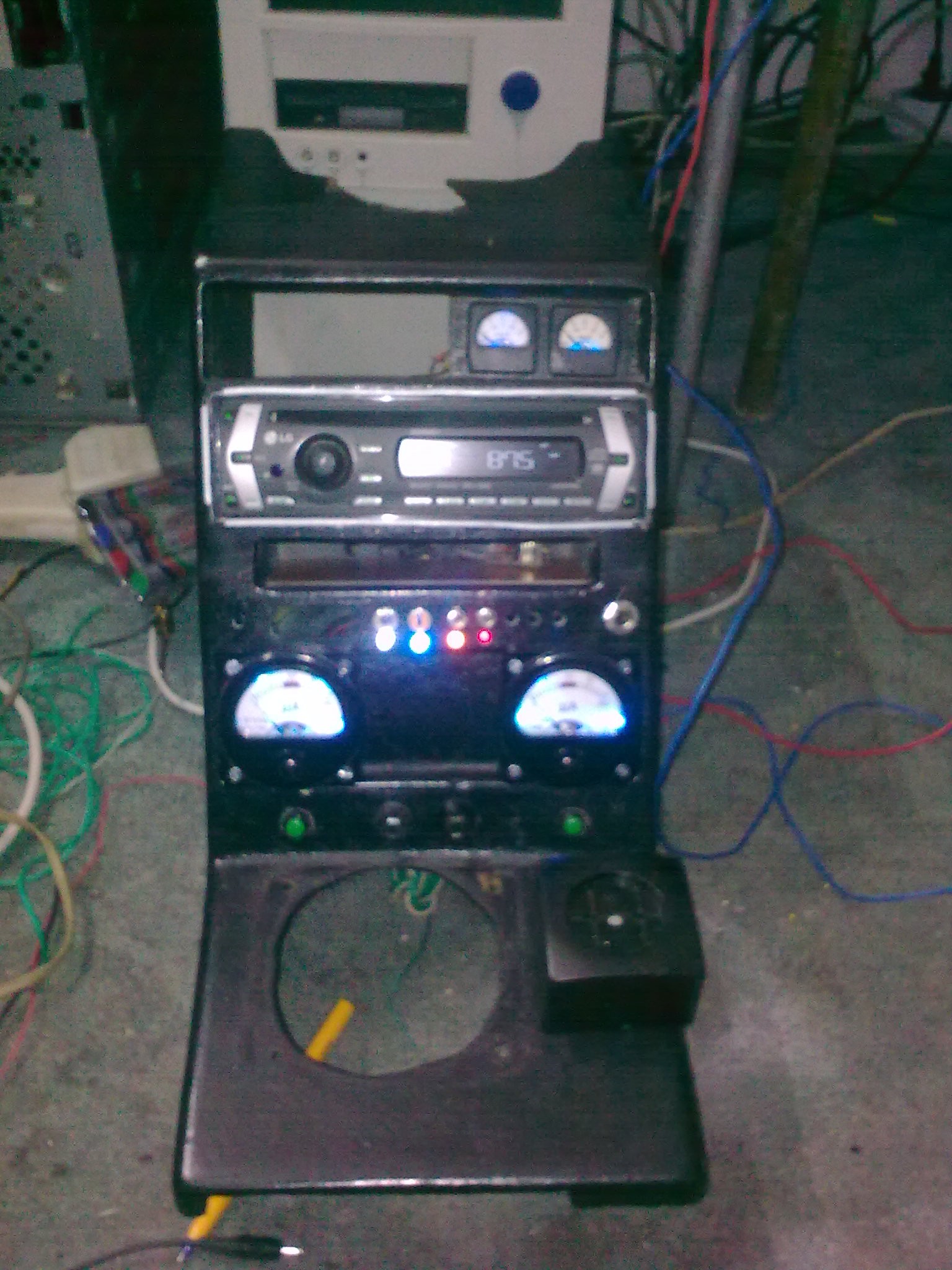
Three additional holes made in front: two cigarette lighter connectors (phone + portable refrigerator - right side) and one for the earphones+microphone connector which goes to my army CB radio transceiver. This one does not fit yet. Needs rework.![]()
![]()
Input stage, equalizer and 12V to +/-24V inverter installed. That DB37 connector is responsible with system power up and speaker outputs.
Installed in the enclosure, powered up and working. Left side of gear shifter, in the big hole - connector for CB transceiver.![]()
Some small CRT tube should fit nicely in the square between the two big meters. Audio graphic analyzer oscilloscope-type.
Next log - detecting radiations.
[END OF TRANSMISSION]
______________________________________
kernel panic: improbability coefficient below zero
-
Wireless solar-powered liquid level sensor - ESP8266-based
05/29/2016 at 21:29 • 0 commentsIf I see any wires today, I will go insane for good. No more wires for this update log. Today - wireless approach.
They say the French started to dig some archaeologic hole and they found wires after 6 feet (2 meters) depth. They concluded they had communication network since 1700s. The British went mad after this discovery and they dug around 9 feet (3.5m) until they also found wires. In conclusion, the Brits were ahead of the French with another 100 years. The Romanians dug some 100 feet (50 meters) pit and found nothing. In conclusion - 2000 years ago we already had wireless telecommunication networks.
Good. I want to see how much gasoline I have in my tank. And if anyone asks me to remove the dash console one more time to find the gasoline level wire, then someone should call the emergency number and ask for neuropsychiatry hospital.
Because everyone on Hackaday is talking about the ESP8266 and its amazing properties, let's get one and torture it.
Also we need an ultrasonic fluid level sensor, just like this one - JSN-SR04T (google).
Also my old love - Arduino Due, a solar panel shield, some lithium accumulators and a custom-made shield for Wifi and level sensor.
The master side will be the RasPI powered by FreeBSD Unix 11.0-CURRENT.
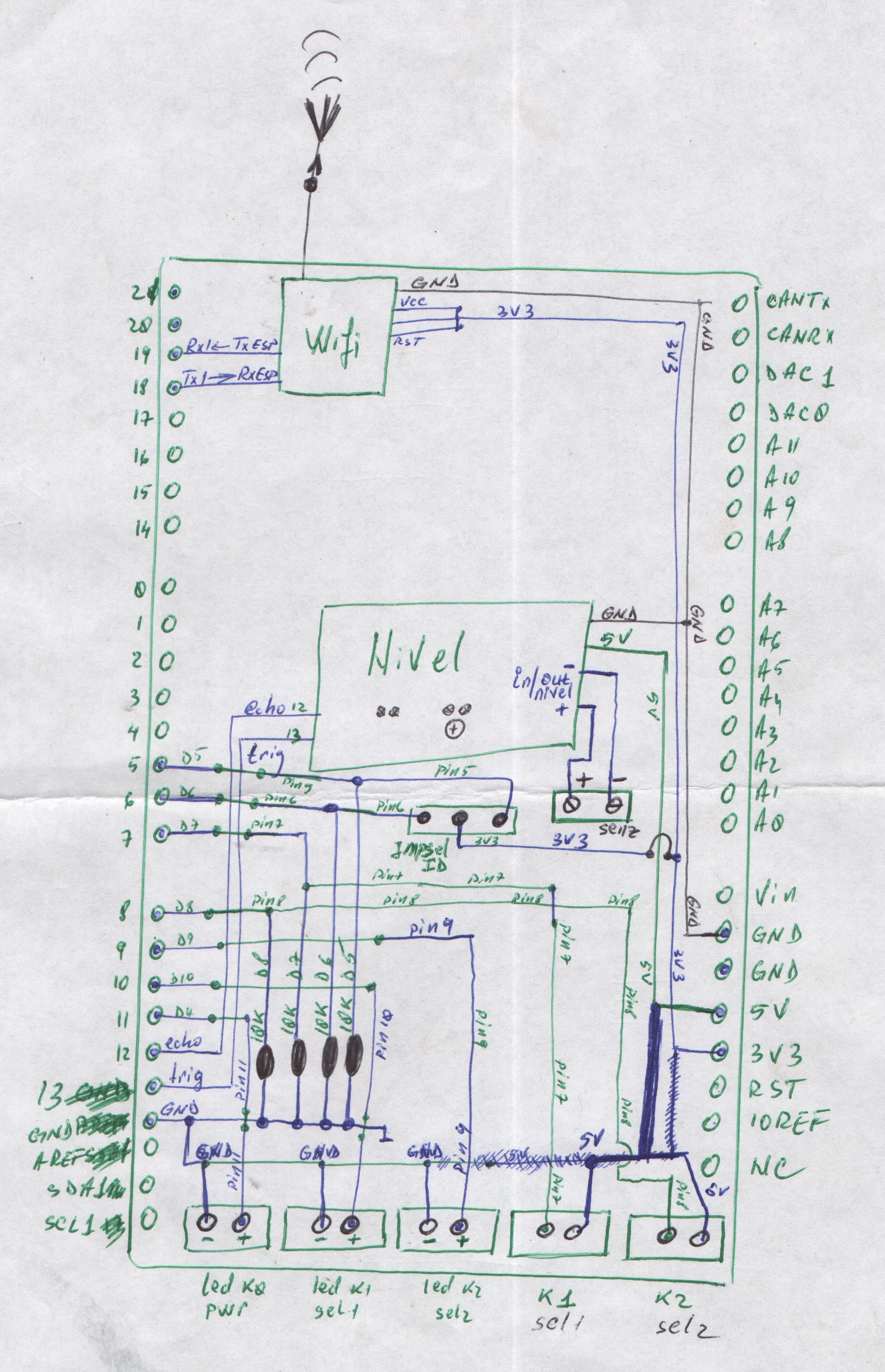
First, the schematic - drawn by hand as usual:
![]() "Nivel" means "level".
"Nivel" means "level".There's also a jumper called "ID". So If I need more sensors, they must identify themselves so the server knows which one is transmiting. Maxmum 4 sensors for now: both pins unselected, both pins selected and only one pin selected. Pins D5 and D6.
The pinouts for ESP and level sensors are as following:
![]()
The client and server side software are placed in the Files section.
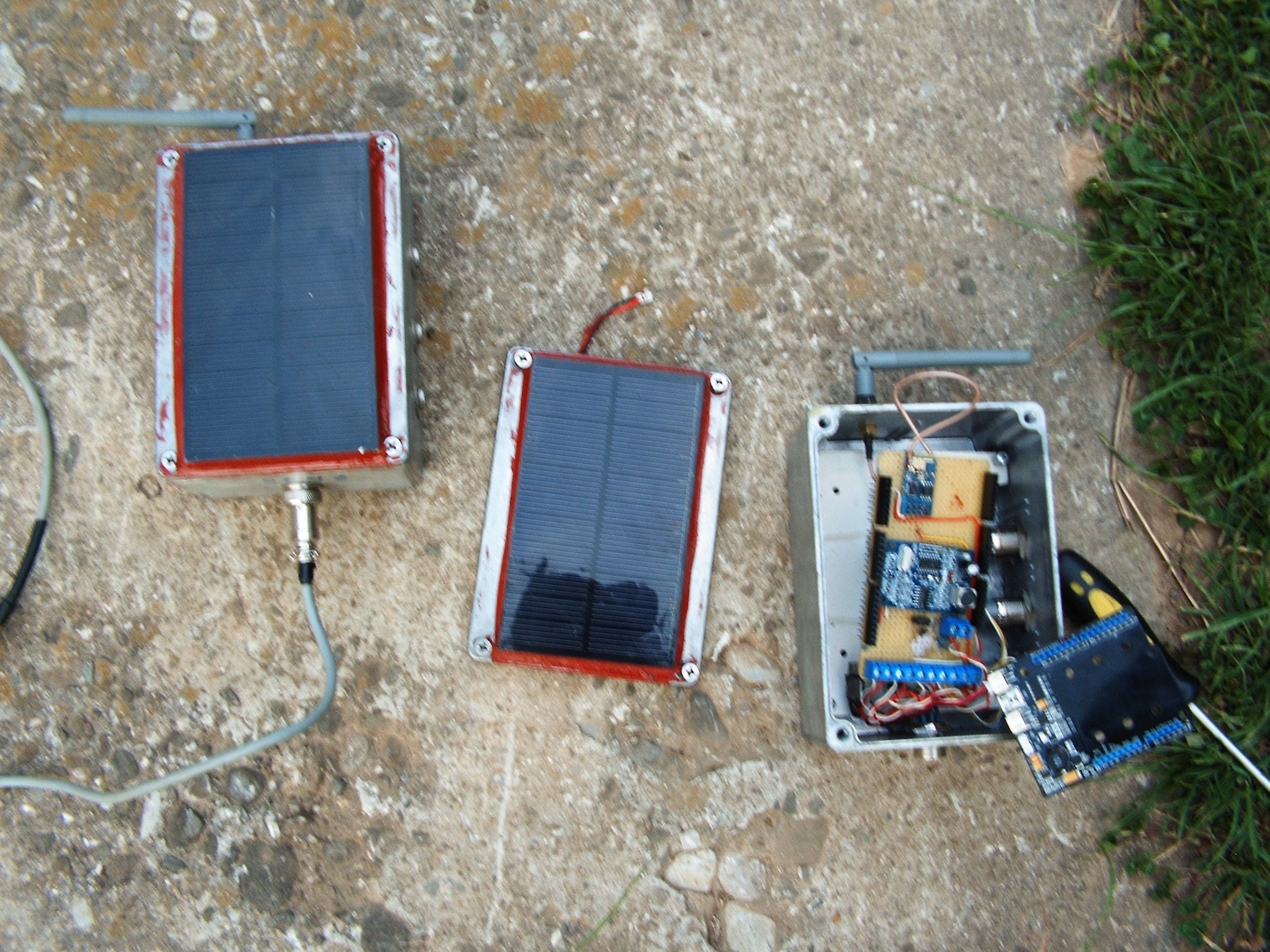
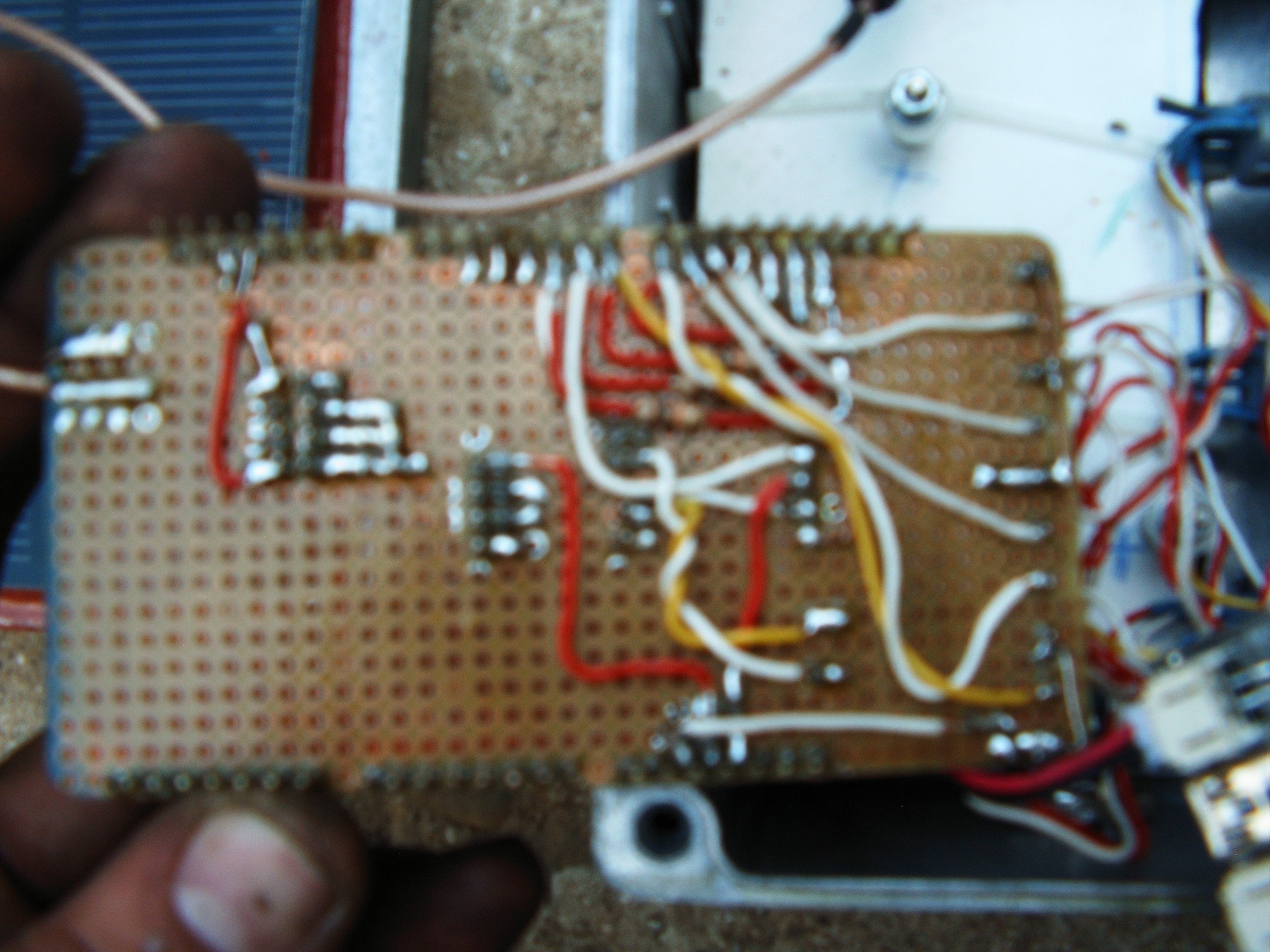
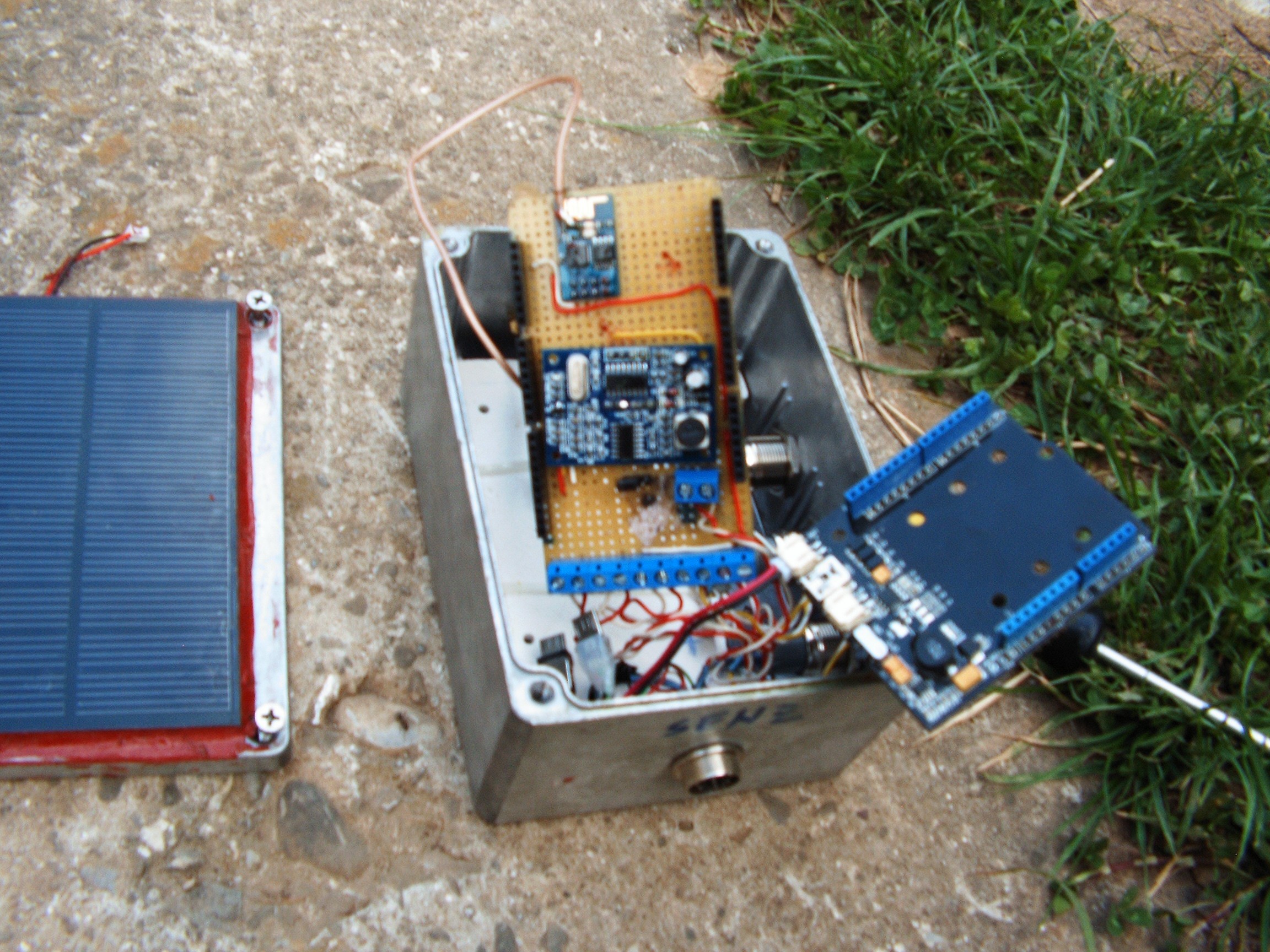
These are my two sensors. Again, trouble with camera focus.
![]()
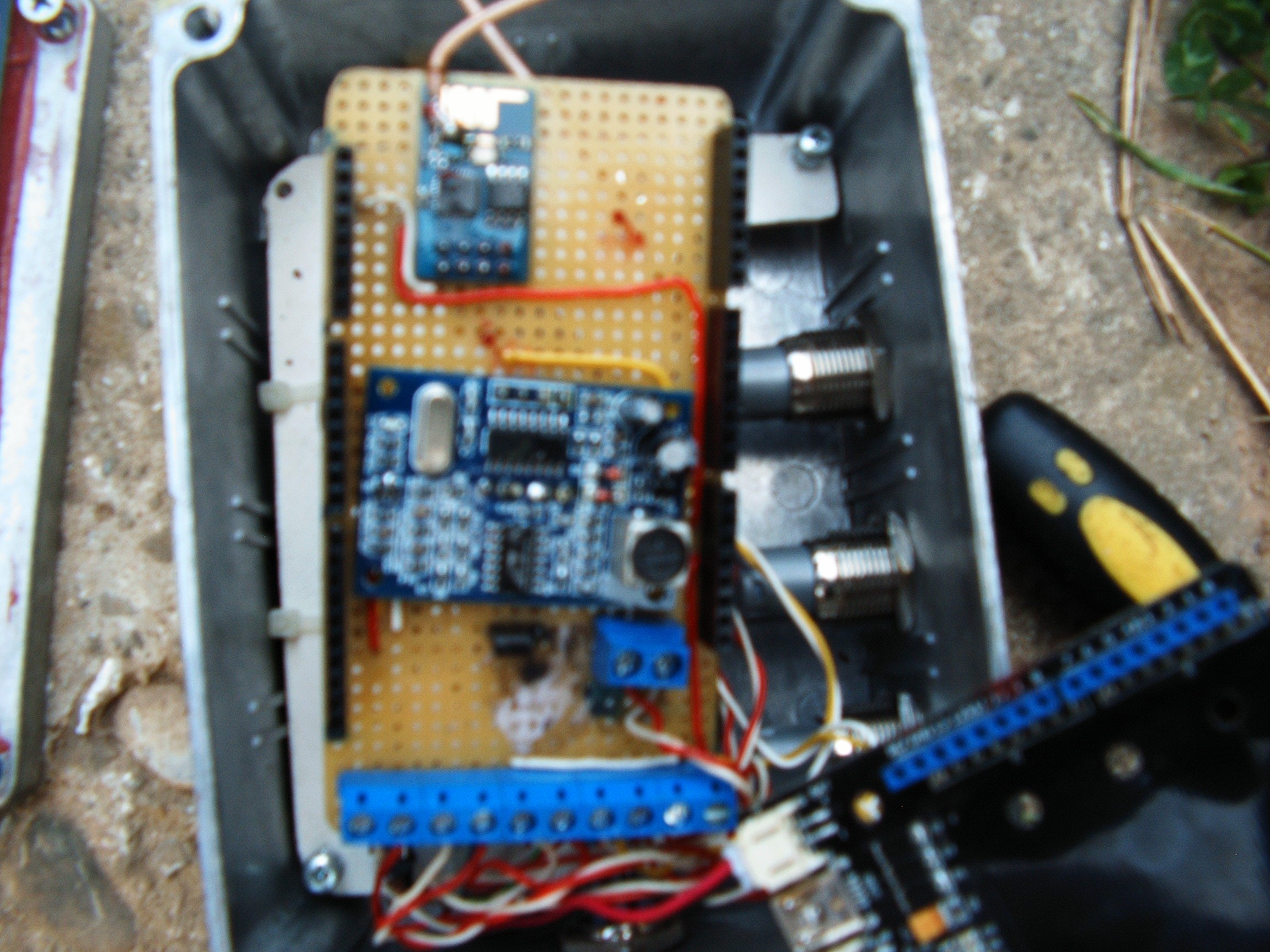
Right side - solar panel shield. The other shield has the schematic listed in the first picture.
![]()
Yes, my hand is burned due to high voltage. Details in the Audio Sound System (II) log.![]()
![]()
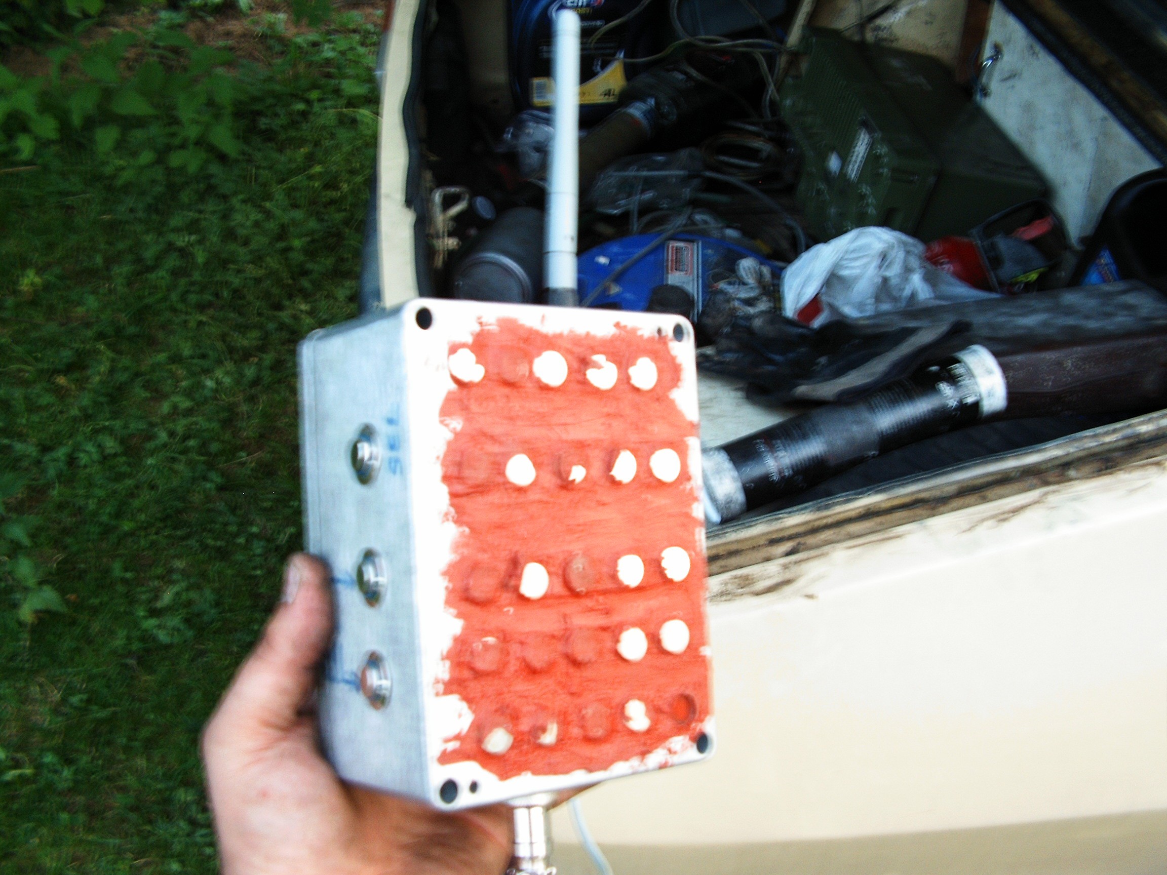
On the back side I placed some magnets in a silicone layer...
![]()
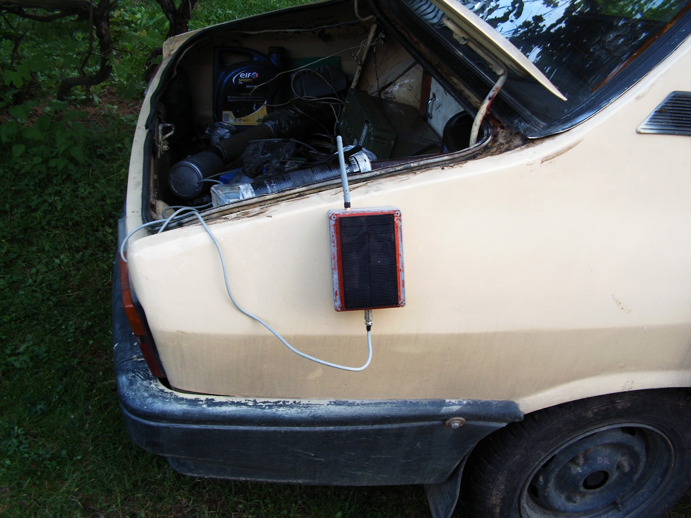
so the sensor can be placed on any vertical metallic surface close to the monitored tank.
![]()
Software:
Sensor side:
Arduino Due. No offense. It has huge processing power and it can do everything that the older arduinos do. And faster.
Server side: Gnu C, FreeBSD Unix. Needs an open access point to work. Mobile phone in AP mode or whatever router. Just don't enable any encryption if you have any older ESPs, the firmware has some undocumented bugs - or I am too lazy to search on the internet.
How it works:
The sensor searches for the server IP and connects. It sends the measured level in centimeters.
The server listens for connections. If any connection fails, the server can fork() another instance of itself when the sensor reconnects, and the OS handles the killing of the inactive instances left. The number is dumped in /usr/local/www/data/index.html which has some 1 second autorefresh() when accessed from a browser.
Work in progress: integrate this with the CANBUS/WITS system, so it can receive the data as a WITS-style string.
Software is uploaded in the Files section.
______________________________________
kernel panic: improbability coefficient below zero
-
Madhouse Reloaded
05/29/2016 at 20:22 • 0 commentsAllright, so we've got a nice terminal, a Raspberry PI running FreeBSD, some CAN-BUS replacement protocol. Let's acquire some data by interfacing with the automobile.
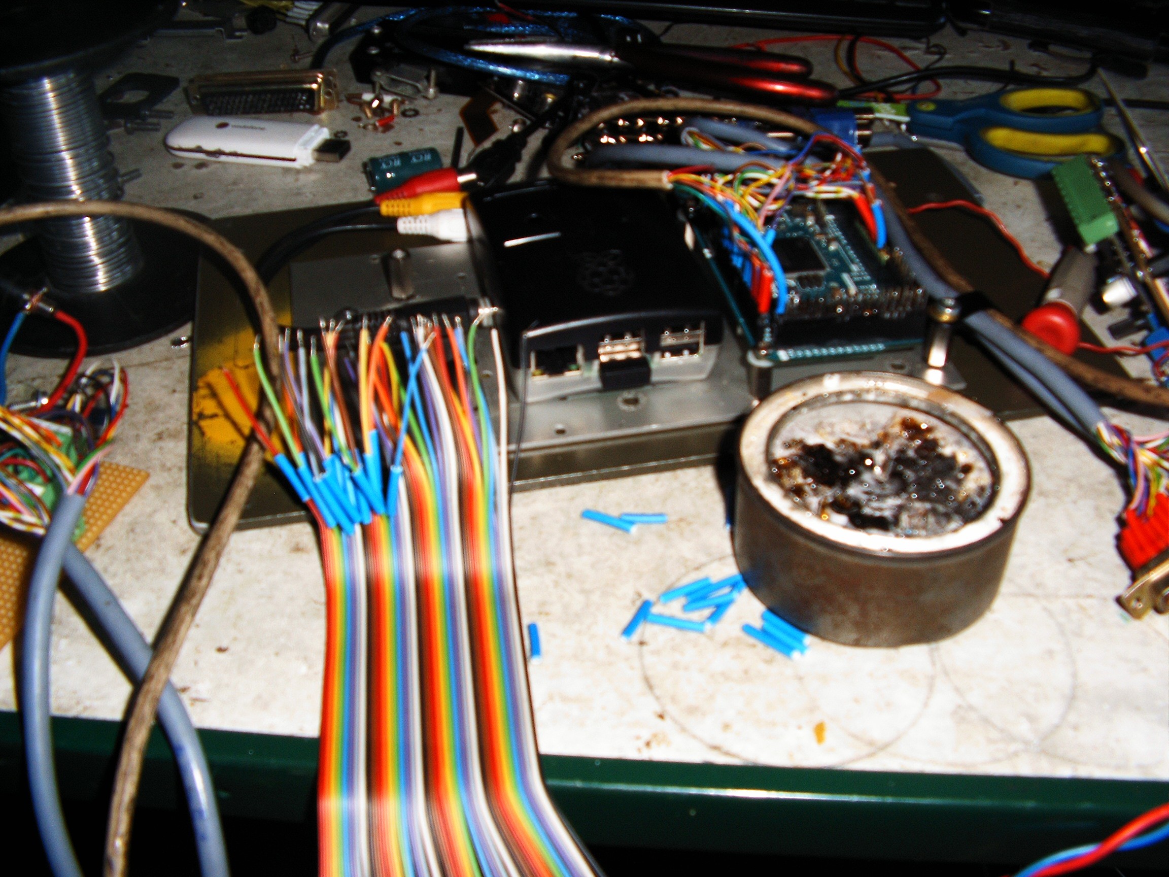
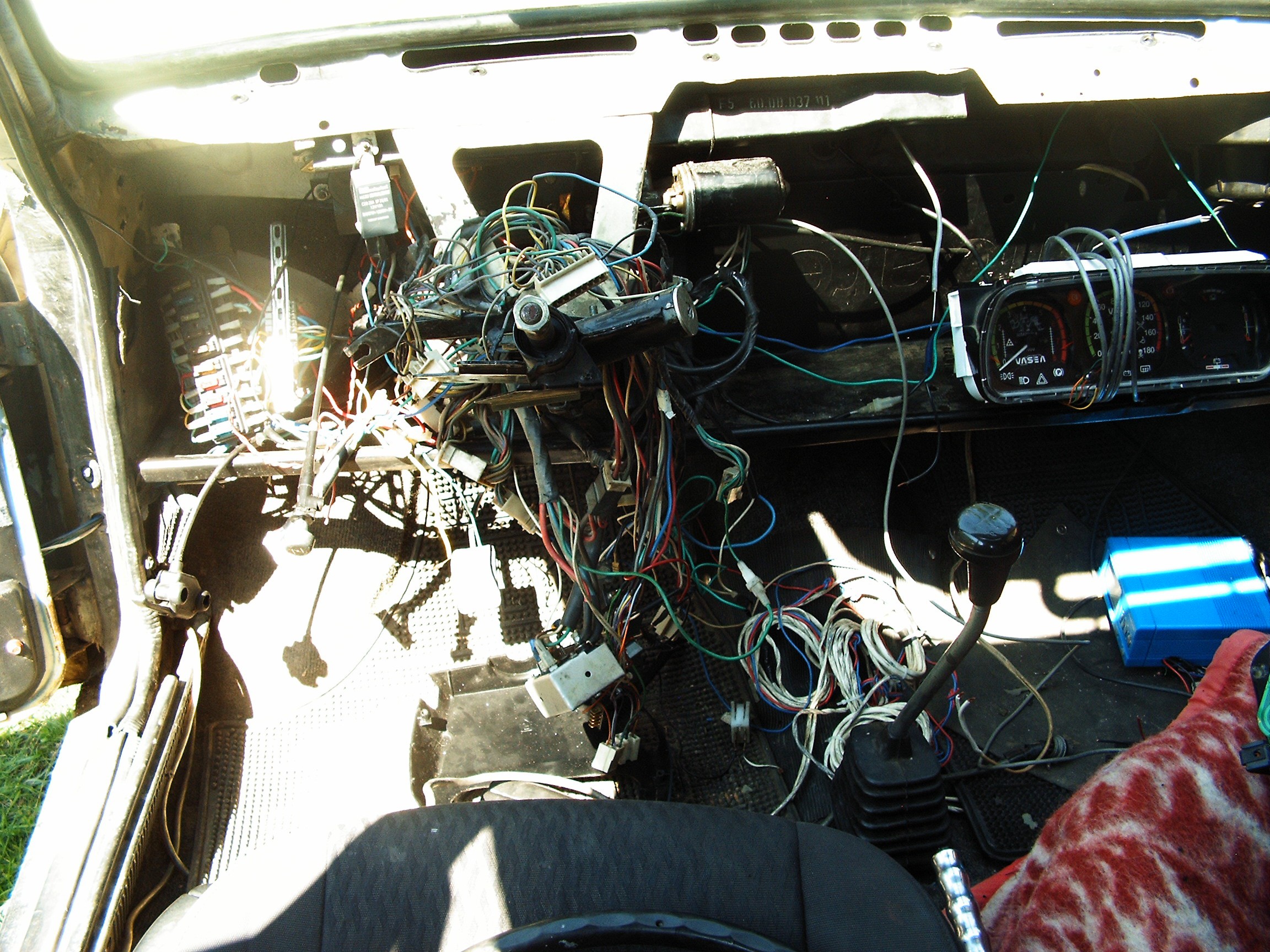
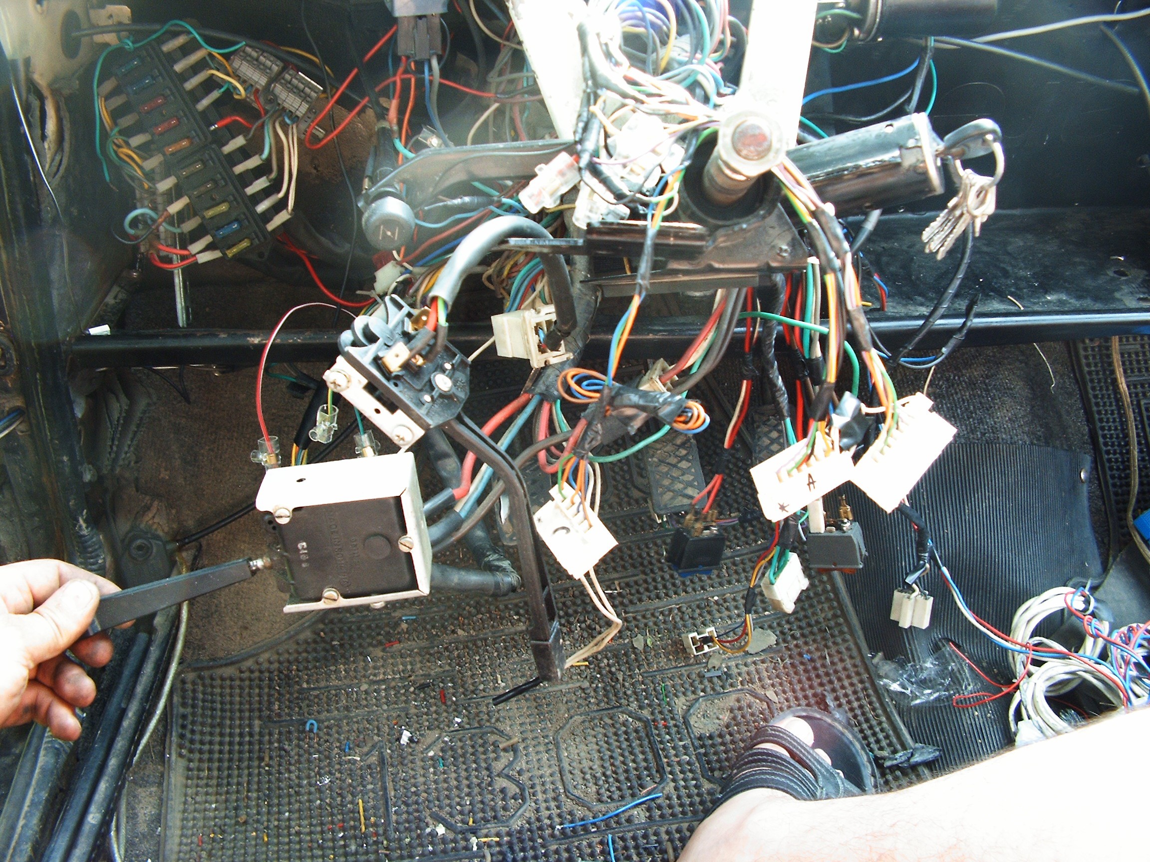
Console down again, this time wire diving into.....
![]()
...the most sadomasochistic wiring I have ever had to solve.
Welcome to the Madhouse. It's so hot outside that my usual IQ booster (my favorite beer) would send me straight to beauty sleep.
Nothing written, nothing documented, schematics on the internet have nothing to do with this mess. Classic communist piggery. I need to MacGyver this insanity with nothing but my old analog meter and a knife. And of course soldering everything plus ducktape to keep sparks away.
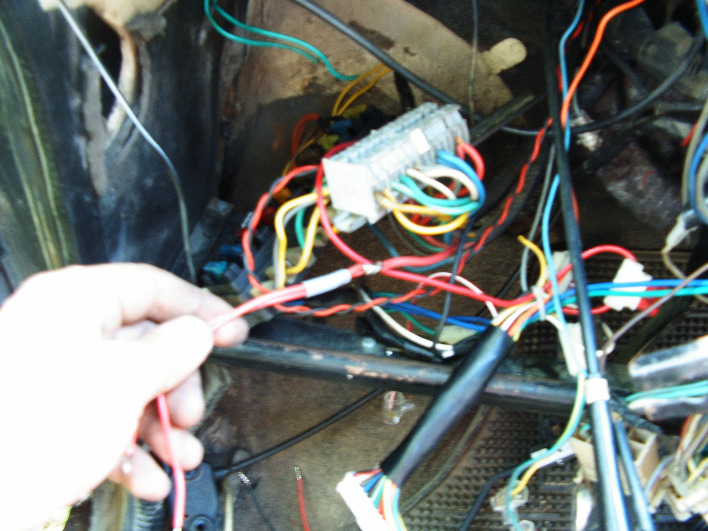
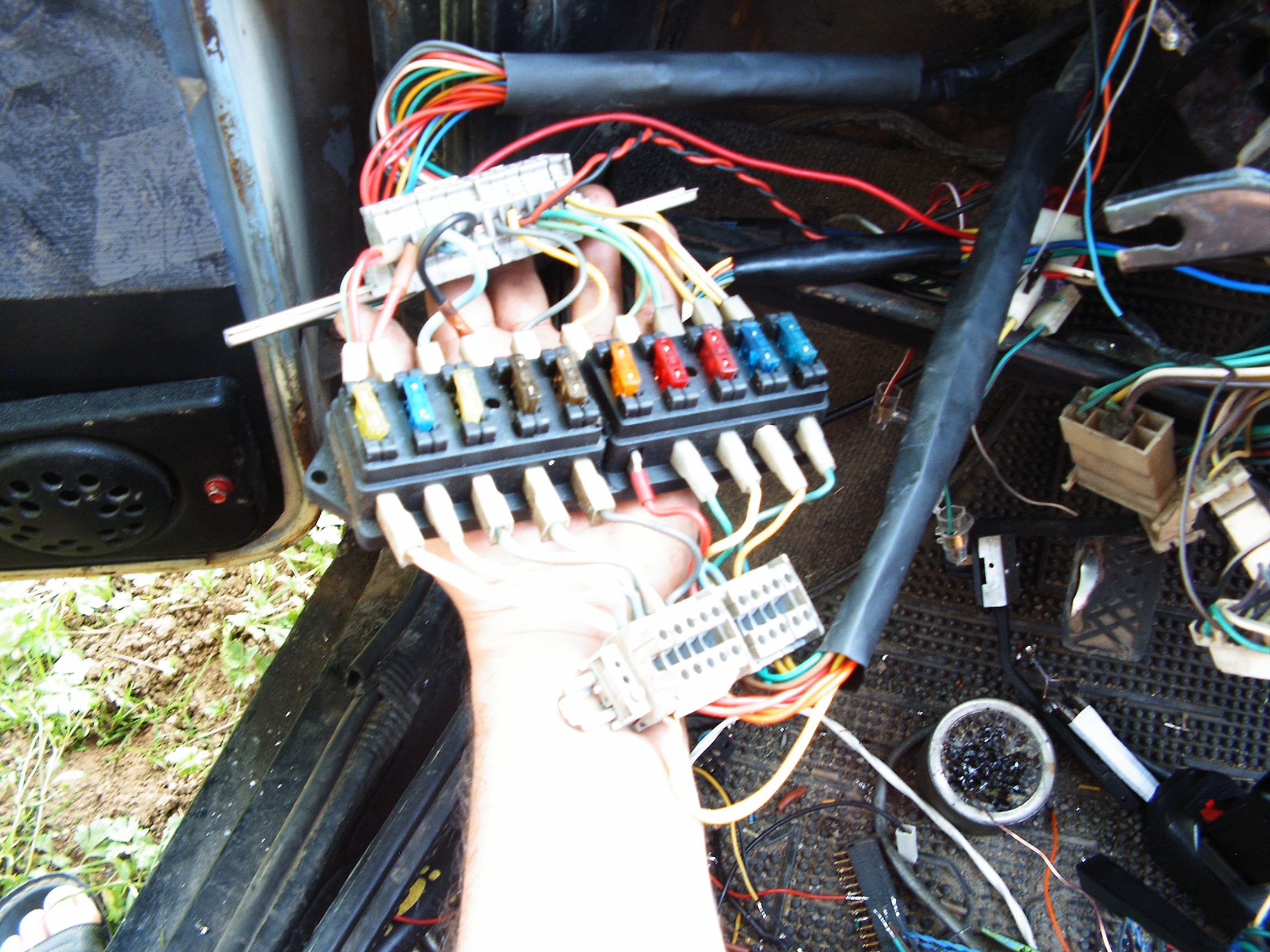
4 hours later I identified all the wires that should go through a fuse panel.
There's a problem with my camera, it does not always focus.
![]()
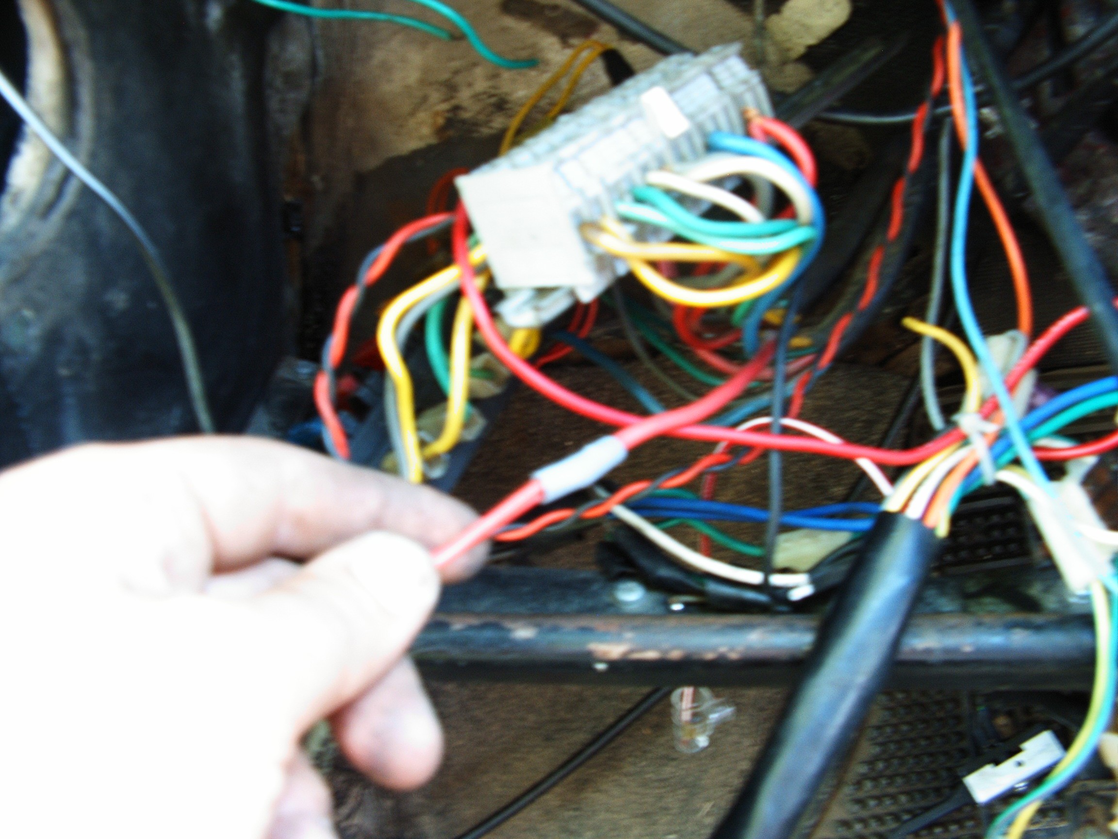
They say they no longer build things like they used to. This is true. Commercial products are now a priority. A few things are built to last forever. To keep things old-school, the work must also be done old-school. So the red wire is the short lights line. Soldered.
![]() Then, a cable plastic coating applied on top of the soldering. While driving, the wires vibrate and move. The soldered area is hard, the rest of the cable is soft. After years of repeated process, the area at the start of soldering... will begin to break and the cable will become interrupted. So this little hack keeps the vibrations away from the problematic area.
Then, a cable plastic coating applied on top of the soldering. While driving, the wires vibrate and move. The soldered area is hard, the rest of the cable is soft. After years of repeated process, the area at the start of soldering... will begin to break and the cable will become interrupted. So this little hack keeps the vibrations away from the problematic area.
Finally, isolation tape to prevent the extra-coating from slipping.![]()
And in that mess there are A LOT of interrupted cables, contacts isolated in a hurry, a lot of "work" done in the most offensive unprofessional way. It is amazing why no short-circuits happened all this time.
Finally - the fuse panel is ready:
![]()
Bottom right: that's my solder gun. It's 40 years old, I use that even on tiny boards. And in the places I work, any professional precision soldering equipment will become recycling material, it will not resist. I can do precision operations with this old monster under microscope by manually keeping the temperature under control (button play). But for now - just old thick cables.
![]()
Finally all the madness starts to make sense. And surprise - the car is able to start in this horrible state. Even without steering wheel attached. Try to do this with a modern vehicle. Oldies but goldies.
Top-left: fuse panel kept in place with a spare wire;
bottom: driving lights control and direction signaling controls.
The rectangular connectors go to the gauges, there are two buttons and another connector for windshield wipers.
And I removed A LOT of cables which just sat there, no functions at all, they were just starting from a place (no connector) and going to other places and of course no connectors.
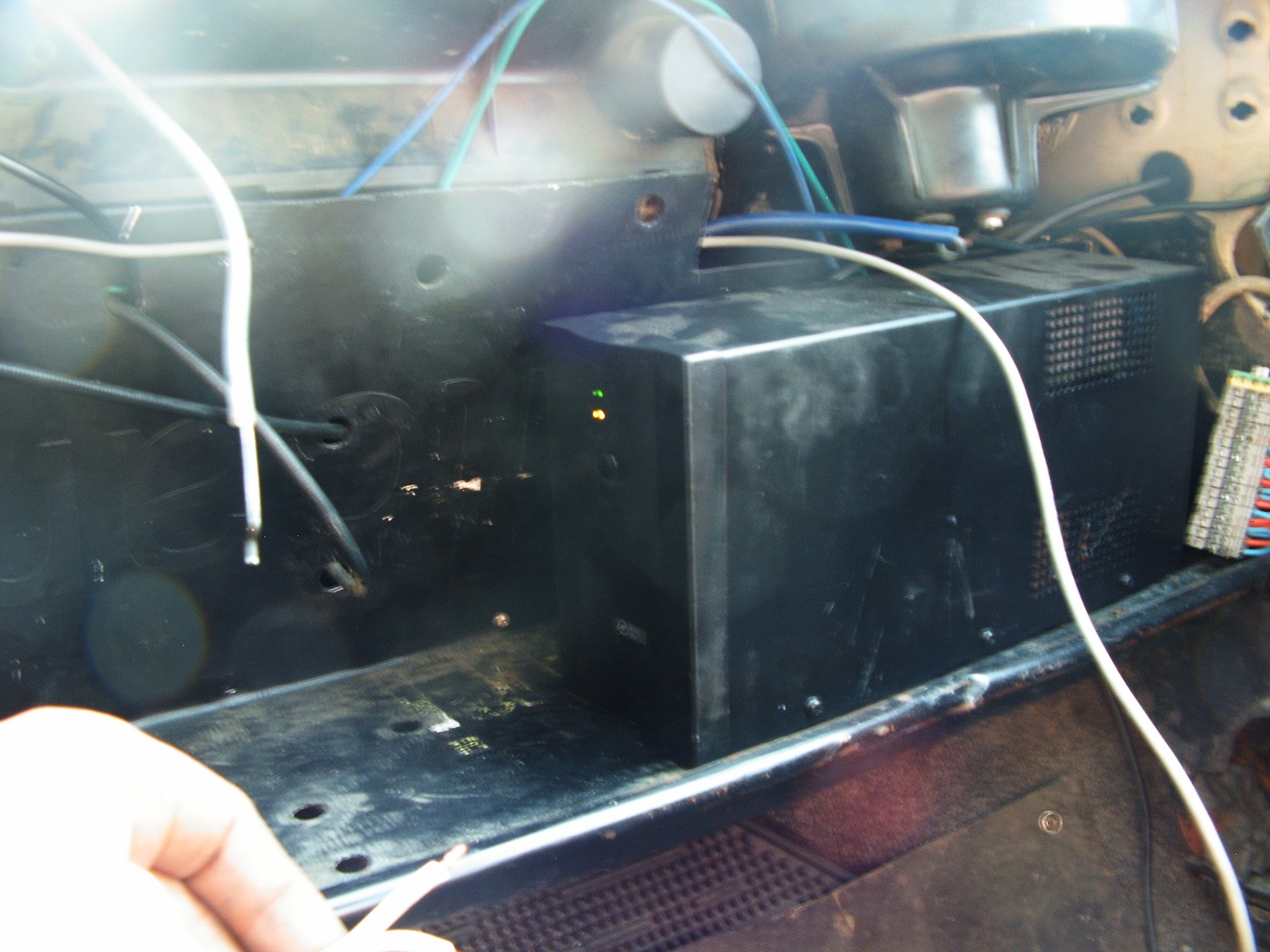
This UPS will be perfect. Powered from the car battery.![]()
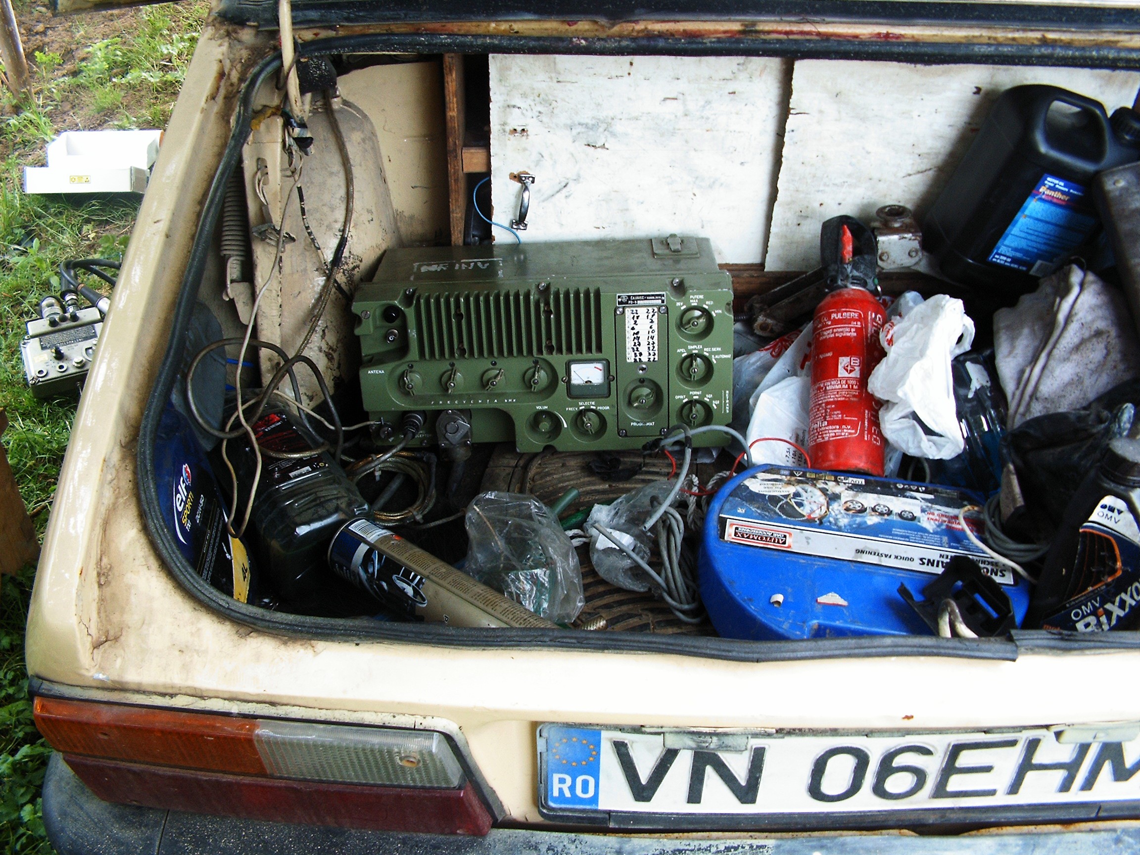
I need a 220 Volts power supply for the audio system...
...and for my CB radio transceiver. Army issued, code name UGAR and it is documented here.![]()
Unfortunately I can not use the other radio station (R123M, soviet army issued) because on transmission mode it sucks so much power that it kills the engine.
The hardest part of this operation is to install the console back in its place. And of course the camera ate the batteries while taking the picture... no pic with this operation unfortunately.
Next log - wireless wizardry.
[END OF TRANSMISSION]
______________________________________
kernel panic: improbability coefficient below zero
-
CAN-BUS REDUX (1) - Slave side
05/04/2016 at 12:06 • 0 commentsSlave-side software is almost done, so it's time to make it public.
No GitHub account, nothing. Just copy-paste this into an arduino Sketch, go get the parts, find the missing libraries and it will work.
Some terms are in Romanian but as a "comment" the English translations are also provided.
Hardware ingredients:
- 2 x automotive gauges (stepper motors) with three connectors: +V, +SIG and GND. +V goes to +12V; +SIG goes to ULN-2003 outputs, GND goes to minus.
- 1 x ULN2003: outputs go to stepper motors (gauges), inputs come from an Adafruit 16-Channel 12-bit PWM/Servo Driver - I2C interface (PCA9685). This one is required to protect the PCA9685 - because it works with max. 6V and the automobile gauges require at least 12V.
- 1 x PCA9685 Adafruit 16-Channel 12-bit PWM/Servo Driver - I2C interface;
- 1 x Arduino Due;- 1 x Liquid Flow sensor Olimex SNS-FLOW401 - with the same functionality as Olimex SNS-FLOW201 (but more sensitive) and GitHub Water Flow Gauge Software;
- 1 x Light Intensity Sensor ( whatever light brick sensor ) capable of analog output proportional with ambient light intensity;
- 1 x TLC5947 Adafruit 24-Channel 12-bit PWM LED Driver - SPI Interface to control the back lights and pointer lights for the gauges;
- a ton of patience.
Software ingredients - pieces of software.
For making everything possible, all Credits and Respect will go as following:
- Arduino Task Scheduler Library Copyright (c) 2015 Anatoli Arkhipenko;
- Adafruit PWM LED driver library.
Analog/Digital connections will be performed according to the defined pins in the code.
The data is outputted via Serial.print() to the serial programming port. No SerialUSB streams are currently detected by FreeBSD 11.0-CURRENT-RPI2 due to some imprefect usb-modem drivers.
This is slave-side software. Master-side software will come soon.
"Code Snippet" displays the software in some bad way. Copy-paste it into an Arduino Sketch and it will appear normal. Also, it seems the Code Snippet somehow removes all the #include libraries. Syntax highlighting causes problems - it does not allow me to upload the log unless the "no syntax" is chosen.
How does it work?
- Every 5 seconds the task scheduler execute the wits() function, which sends out all "hotdogs" through the serial line. There are no visible delays, meaning the process is not "visible" paused;
- Ambient light is measured and gauges back light + pointer light intensities are modified according to the environment;
- All this big amount of data is defined as a structure so everything can later be pushed to some "black box recorder" for later inspections with little effort;
- One of the gauges outputs the light intensity, the other outputs the fluid flow while blowing through the flow sensor.
#include <TaskScheduler.h> /* DEFINES: GAUGES */ #include <Wire.h> #include <Adafruit_PWMServoDriver.h> /* DEFINES: dials lights */ #include "Adafruit_TLC5947.h" #define NUM_TLC5974 1 #define data 4 #define clock 5 #define latch 6 #define oe_lights -1 // set to -1 to not use the enable pin (its optional) Adafruit_TLC5947 tlc = Adafruit_TLC5947(NUM_TLC5974, clock, data, latch); /* PWM CHANNELS THESE ARE NOT ARDUINO DIGITAL CHANNELS!!! */ const byte canal_limba_gaz = 0x00; // "canal" = "channel"; "limba" = "tongue"/"pointer needle" const byte canal_cadran_gaz = 1; // "cadran = "dial"; "gaz" = gas; const byte canal_limba_apa = 2; // "apa" = "water"/"coolant liquid" const byte canal_cadran_apa = 3; const byte canal_limba_bat = 4; // "bat" = battery const byte canal_cadran_bat = 5; const byte canal_limba_ulei = 6; // " ulei " = "oil" const byte canal_cadran_ulei = 7; const byte canal_limba_kmh = 8; const byte canal_limba_rpm = 9; const byte canal_limba_rad = 10; const byte canal_limba_electro = 11; const byte canal_cadran_kmh_5 = 23; const byte canal_cadran_kmh_4 = 22; const byte canal_cadran_kmh_3 = 21; const byte canal_cadran_kmh_2 = 20; const byte canal_cadran_kmh_1 = 19; const byte canal_cadran_rpm_5 = 18; const byte canal_cadran_rpm_4 = 17; const byte canal_cadran_rpm_3 = 16; const byte canal_cadran_rpm_2 = 15; const byte canal_cadran_rpm_1 = 14; const byte canal_iluminare_superioara = 13; // "channel for upper dash lights /* end DEFINES: lights */ //######################################################################################### /* DEFINES: GAUGES */ Adafruit_PWMServoDriver pwm = Adafruit_PWMServoDriver(0x40); int oe_gauges = -1; /* end DEFINES: GAUGES */ //######################################################################################### /* DEFNIES: CANBUS WITS STYLE */ struct WITS_CONFIG { /* index / categories */ const int8_t num_cats = 0x05; const int8_t cat_pwr_ctrl = 0x00; // index0 - computer power controls const int8_t cat_measurements = 0x01; // index1 - measurements const int8_t cat_manual_input_state = 0x02; // index2 - manual input states const int8_t cat_autowarning = 0x03; // index3 -- automatic input states const int8_t cat_ambient_params = 0x04; // index4 - ambient parameters const int8_t cat_TBD = 0x05; // index5 - to be determined /* pos */ /* index 0 computer power controls */ const int8_t num_idx0 = 0x02; const int8_t pwr_relay0 = 0x00; const int8_t pwr_relay1 = 0x01; int index0[2]; bool index0_modif[2] = { false, false }; /* index 1 measurements*/ const int num_idx1 = 0x0A; const int8_t gas_level = 0x00; const int8_t core_temp = 0x01; const int8_t bat_voltage = 0x02; const int8_t engine_core_press = 0x03; const int8_t speed_kmh = 0x04; const int8_t rpm = 0x05; const int8_t rads = 0x06; const int8_t battchg = 0x07; const int8_t gas_lpm = 0x08; const int8_t gas_inst = 0x09; int index1[0x0A]; bool index1_modif[0x0A] = {false, false, false, false, false, false, false, false, false, false }; // index modif - is any of these parameters under manual calibration? /* index 2 manual input states / user input states / user interaction states */ const int num_idx2 = 0x17; const int8_t poz_lights = 0x00; const int8_t short_lights = 0x01; const int8_t long_lights = 0x02; const int8_t rear_fog_lights = 0x03; const int8_t front_fog_lights = 0x04; // projectors const int8_t dir_signal_left = 0x05; const int8_t dir_signal_right = 0x05; const int8_t foot_brake = 0x06; const int8_t manual_brake = 0x07; const int8_t belt_driver = 0x08; const int8_t seat_driver = 0x09; const int8_t belt_left = 0x0A; const int8_t seat_left = 0x0B; const int8_t belt_3 = 0x0C; const int8_t seat_3 = 0x0D; const int8_t belt_4 = 0x0E; const int8_t seat_4 = 0x0F; const int belt_5 = 0x10; const int seat_5 = 0x11; const int front_left_door = 0x12; const int front_right_door = 0x13; const int rear_left_door = 0x14; const int rear_right_door = 0x15; const int trunk = 0x16; const int marche_a_rierre = 0x17; bool index2[0x17]; bool index2_modif[0x17] = { false, false, false, false, false, false, false, false, false, false, false, false, false, false, false, false, false, false, false, false, false, false }; /* index 3 automatic input states */ const int num_idx3 = 0x04; const int8_t low_fuel_alarm = 0x00; const int8_t overheat_alarm = 0x01; const int8_t low_press_alarm = 0x02; const int8_t vent_engine_alarm = 0x03; const int8_t neural_net_alarm = 0x04; bool index3[0x04]; byte index3_modif[5] = { false, false, false, false }; /* index 4 ambient parameters */ const int num_idx4 = 0x17; const int8_t ambient_light = 0x00; const int8_t power_state = 0x01; const int8_t bk_gas_gauge = 0x02; const int8_t pointer_gas_gauge = 0x03; const int8_t bk_press_gauge = 0x04; const int8_t pointer_press_gauge = 0x05; const int8_t bk_batt_gauge = 0x06; const int8_t pointer_batt_gauge = 0x07; const int8_t bk_coretemp = 0x08; const int8_t pointer_coretemp = 0x09; const int8_t bk_speed_0 = 0x0A; const int8_t bk_speed_1 = 0x0B; const int8_t bk_speed_2 = 0x0C; const int8_t bk_speed_3 = 0x0D; const int8_t bk_speed_4 = 0x0E; const int8_t pointer_speed_gauge = 0x0F; const int bk_rpm_0 = 0x10; const int bk_rpm_1 = 0x11; const int bk_rpm_2 = 0x12; const int bk_rpm_3 = 0x13; const int bk_rpm_4 = 0x14; const int pointer_rpm_gauge = 0x15; const int pointer_rad_gauge = 0x16; const int pointer_chg_gauge = 0x17; int index4[0x17]; byte index4_modif[0x17] = { false, false, false, false, false, false, false, false, false, false, false, false, false, false, false, false, false, false, false, false, false, false }; } sysctl; // END DEFINES: CANBUS //######################################################################################### /* DEFINES: DIGITAL OUTPUT CHANNELS WITS CAT 0 */ #define pin_relay0 0 #define pin_relay1 0 //######################################################################################### /* DEFINES: ANALOG INPUT CHANNELS WITS CAT 1 analog inputs? LAN-AD16? USB-AD12? */ #define pin_gas_sensor A0 //######################################################################################### /* DEFINES: DIGITAL INPUT CHANNELS WARNING: OPTOCOUPLERS!!! */ // WITS CAT 2 #define pin_poz_lights 22 #define pin_short_lights 23 #define pin_long_lights 24 #define pin_rear_fog_lights 25 #define pin_front_fog_lights 26 #define pin_dir_signal_left 27 #define pin_dir_signal_right 28 #define pin_foot_brake 29 #define pin_manual_brake 30 #define pin_belt_driver 31 #define pin_seat_driver 32 #define pin_belt_left 33 #define pin_seat_left 34 #define pin_belt_3 35 #define pin_seat_3 36 #define pin_belt_4 37 #define pin_seat_4 38 #define pin_belt_5 39 #define pin_seat_5 40 #define pin_front_left_door 41 #define pin_front_right_door 42 #define pin_rear_left_door 43 #define pin_rear_right_door 44 #define pin_trunk 45 #define pin_marche_a_rierre 46 //######################################################################################### // WITS CAT 3 #define pin_low_fuel_alarm 47 #define pin_coreoverheat_alarm 48 #define pin_low_corepress_alarm 49 #define pin_vent_engine_alarm 50 #define pin_neural_net_alarm 51 // END DEFINES: DIGITAL INPUT CHANNELS //######################################################################################### // smooth() const int NumReadings = 4096; int idx = 0; int lightreadings[NumReadings]; long int lighttotal = 0; int lightavg = 0; int light = 0; int light_prev = 0; // prototipe for wits function void wits(); // define wits task to run forever at 5 seconds interval Task t1(5000, TASK_FOREVER, &wits); // task scheduler Scheduler runner; void setup() { Serial.begin(115200); //analogReadResolution(12); gauges_setup(); Wire.begin(); pwm.begin(); pwm.setPWMFreq(150); yield(); setup_gas(); setup_bklights(); setup_input_pins(); setup_output_pins(); poweron(); runner.init(); runner.addTask(t1); t1.enable(); } void loop() { read_gas(true); light_prev = sysctl.index4[sysctl.ambient_light]; read_light_sensor(); if (sysctl.index4[sysctl.ambient_light] != light_prev) bklights(); process_cat2(); process_cat3(); setgauge(1, sysctl.index1[sysctl.gas_inst]); //setgauge(0, sysctl.index4[sysctl.ambient_light]); setgauge(0, light); // finaly send everything to serial line runner.execute(); } //######################################################################################### //WITS CAT/IDX 0 powerstates void setup_output_pins() { pinMode(pin_relay0, OUTPUT); pinMode(pin_relay1, OUTPUT); } //######################################################################################### void poweron() { digitalWrite(pin_relay0, HIGH); digitalWrite(pin_relay1, HIGH); } //######################################################################################### /* WITS CAT/IDX1 GAS SENSOR WITS CAT/IDX 0001 POS: 0000 - level 0008 - litri/min 0009 - instant consum ml/s */ byte GasSensorPin = 2; float calibrationFactor = 4.5; volatile byte pulseCount; float flowRate; unsigned int flowMilliLitres; unsigned long totalMilliLitresA; unsigned long totalMilliLitresB; unsigned long oldTime; void setup_gas() { pinMode(GasSensorPin, INPUT); digitalWrite(GasSensorPin, HIGH); pulseCount = 0; flowRate = 0.0; flowMilliLitres = 0; totalMilliLitresA = 0; totalMilliLitresB = 0; oldTime = 0; attachInterrupt(digitalPinToInterrupt(GasSensorPin), GasPulseCounter, FALLING); } void GasPulseCounter() { pulseCount++; } void read_gas(bool modif) { if ((millis() - oldTime) > 1000) { // Only process counters once per second detachInterrupt(digitalPinToInterrupt(GasSensorPin)); flowRate = ((1000.0 / (millis() - oldTime)) * pulseCount) / calibrationFactor; oldTime = millis(); flowMilliLitres = (flowRate / 60) * 1000; totalMilliLitresA += flowMilliLitres; totalMilliLitresB += flowMilliLitres; unsigned int frac; /*Serial.print(int(flowRate)); // Print the integer part of the variable Serial.print("."); // Print the decimal point */ frac = (flowRate - int(flowRate)) * 10; sysctl.index1[sysctl.gas_lpm] = (int)(flowRate * 10); sysctl.index1_modif[sysctl.gas_lpm] = modif; sysctl.index1[sysctl.gas_inst] = flowMilliLitres; sysctl.index1_modif[sysctl.gas_inst] = modif; /*Serial.print(frac, DEC) ; // Print the fractional part of the variable Serial.print("L/min "); Serial.print(" "); // Output separator Serial.print(flowMilliLitres); Serial.print("mL/s"); Serial.print(" Total Counter A: "); Serial.print(totalMilliLitresA); Serial.print("mL "); // Output separator Serial.print(" Total Counter B: "); Serial.print(totalMilliLitresB); Serial.println(" mL.\n"); if (modif == true) Serial.print("0>"); else Serial.print("1>"); Serial.print("0001>"); Serial.print("0009>"); if ((flowMilliLitres>= 0x00) && (flowMilliLitres <= 0x0F)) Serial.print("000"); if ((flowMilliLitres > 0x0F) && (flowMilliLitres <= 0xFF)) Serial.print("00"); if (flowMilliLitres > 0xFF) Serial.print("0"); Serial.print(flowMilliLitres, HEX); Serial.println("!!"); */ // Reset the pulse counter so we can start incrementing again pulseCount = 0; // Enable the interrupt again now that we've finished sending output attachInterrupt(digitalPinToInterrupt(GasSensorPin), GasPulseCounter, FALLING); } } /* END WITS CAT1 gaz */ //################################################################################# // WITS CAT/idx 0002 void process_cat2() { sysctl.index2[sysctl.poz_lights] = digitalRead(pin_poz_lights); sysctl.index2[sysctl.short_lights] = digitalRead(pin_short_lights); sysctl.index2[sysctl.long_lights] = digitalRead(pin_long_lights); sysctl.index2[sysctl.rear_fog_lights] = digitalRead(pin_rear_fog_lights); sysctl.index2[sysctl.front_fog_lights] = digitalRead(pin_front_fog_lights); sysctl.index2[sysctl.dir_signal_left] = digitalRead(pin_dir_signal_left); sysctl.index2[sysctl.dir_signal_right] = digitalRead(pin_dir_signal_right); sysctl.index2[sysctl.foot_brake] = digitalRead(pin_foot_brake); sysctl.index2[sysctl.manual_brake] = digitalRead(pin_manual_brake); sysctl.index2[sysctl.belt_driver] = digitalRead(pin_belt_driver); sysctl.index2[sysctl.seat_driver] = digitalRead(pin_seat_driver); sysctl.index2[sysctl.belt_left] = digitalRead(pin_belt_left); sysctl.index2[sysctl.seat_left] = digitalRead(pin_seat_left); sysctl.index2[sysctl.belt_3] = digitalRead(pin_belt_3); sysctl.index2[sysctl.seat_3] = digitalRead(pin_seat_3); sysctl.index2[sysctl.belt_4] = digitalRead(pin_belt_4); sysctl.index2[sysctl.seat_4] = digitalRead(pin_seat_4); sysctl.index2[sysctl.belt_5] = digitalRead(pin_belt_5); sysctl.index2[sysctl.seat_5] = digitalRead(pin_seat_5); sysctl.index2[sysctl.front_left_door] = digitalRead(pin_front_left_door); sysctl.index2[sysctl.front_right_door] = digitalRead(pin_front_right_door); sysctl.index2[sysctl.rear_left_door] = digitalRead(pin_rear_left_door); sysctl.index2[sysctl.rear_right_door] = digitalRead(pin_rear_right_door); sysctl.index2[sysctl.trunk] = digitalRead(pin_trunk); sysctl.index2[sysctl.marche_a_rierre] = digitalRead(pin_marche_a_rierre); } // WITS CAT/IDX 0003 void process_cat3() { sysctl.index3[sysctl.low_fuel_alarm] = digitalRead(pin_low_fuel_alarm); sysctl.index3[sysctl.overheat_alarm] = digitalRead(pin_coreoverheat_alarm); sysctl.index3[sysctl.low_press_alarm] = digitalRead(pin_low_corepress_alarm); sysctl.index3[sysctl.vent_engine_alarm] = digitalRead(pin_vent_engine_alarm); sysctl.index3[sysctl.neural_net_alarm] = digitalRead(pin_neural_net_alarm); } /* backlights / ambient lights WITS CAT/IDX 0004 ambient light WITS CAT/INDEX 0004 POS 0000 - ambient light sensor */ void read_light_sensor() { lighttotal = lighttotal - lightreadings[idx]; light = analogRead(0); lightreadings[idx] = light; lighttotal = lighttotal + lightreadings[idx]; idx = idx + 1; if (idx >= NumReadings) idx = 0; lightavg = lighttotal / NumReadings; //sysctl.index4[sysctl.ambient_light] = (uint16_t) lightavg; //sysctl.index4[sysctl.ambient_light] = analogRead(0); sysctl.index4[sysctl.ambient_light] = lightavg; } void read_light() { //sysctl.index4[sysctl.ambient_light] = analogRead(0); } // dial lights (backlight + "tongue"/"needle" light void setup_bklights() { tlc.begin(); if (oe_lights >= 0) { pinMode(oe_lights, OUTPUT); digitalWrite(oe_lights, LOW); } } // WITS CAT/IDX 0003 void process_cat3() { sysctl.index3[sysctl.low_fuel_alarm] = digitalRead(pin_low_fuel_alarm); sysctl.index3[sysctl.overheat_alarm] = digitalRead(pin_coreoverheat_alarm); sysctl.index3[sysctl.low_press_alarm] = digitalRead(pin_low_corepress_alarm); sysctl.index3[sysctl.vent_engine_alarm] = digitalRead(pin_vent_engine_alarm); sysctl.index3[sysctl.neural_net_alarm] = digitalRead(pin_neural_net_alarm); } void bklights() { uint16_t pwm = 100+sysctl.index4[sysctl.ambient_light] * 10; sysctl.index4[sysctl.bk_gas_gauge] = pwm; sysctl.index4[sysctl.pointer_gas_gauge] = pwm; sysctl.index4[sysctl.bk_press_gauge] = pwm; sysctl.index4[sysctl.pointer_press_gauge] = pwm; sysctl.index4[sysctl.bk_batt_gauge] = pwm; sysctl.index4[sysctl.pointer_batt_gauge] = pwm; sysctl.index4[sysctl.bk_coretemp] = pwm; sysctl.index4[sysctl.pointer_coretemp] = pwm; sysctl.index4[sysctl.bk_speed_0] = pwm; sysctl.index4[sysctl.bk_speed_1] = pwm; sysctl.index4[sysctl.bk_speed_2] = pwm; sysctl.index4[sysctl.bk_speed_3] = pwm; sysctl.index4[sysctl.bk_speed_4] = pwm; sysctl.index4[sysctl.pointer_speed_gauge] = pwm; sysctl.index4[sysctl.bk_rpm_0] = pwm; sysctl.index4[sysctl.bk_rpm_1] = pwm; sysctl.index4[sysctl.bk_rpm_2] = pwm; sysctl.index4[sysctl.bk_rpm_3] = pwm; sysctl.index4[sysctl.bk_rpm_4] = pwm; sysctl.index4[sysctl.pointer_rpm_gauge] = pwm; sysctl.index4[sysctl.pointer_rad_gauge] = pwm; sysctl.index4[sysctl.pointer_chg_gauge] = pwm; tlc.setPWM(canal_limba_gaz, sysctl.index4[sysctl.pointer_gas_gauge]); tlc.write(); tlc.setPWM(canal_cadran_gaz, sysctl.index4[sysctl.bk_gas_gauge]); tlc.write(); tlc.setPWM(canal_limba_apa, sysctl.index4[sysctl.pointer_coretemp]); tlc.write(); tlc.setPWM(canal_cadran_apa, sysctl.index4[sysctl.bk_coretemp]); tlc.write(); tlc.setPWM(canal_limba_bat, sysctl.index4[sysctl.pointer_batt_gauge]); tlc.write(); tlc.setPWM(canal_cadran_bat, sysctl.index4[sysctl.bk_batt_gauge]); tlc.write(); tlc.setPWM(canal_limba_ulei, sysctl.index4[sysctl.pointer_press_gauge]); tlc.write(); tlc.setPWM(canal_cadran_ulei, sysctl.index4[sysctl.bk_press_gauge]); tlc.write(); tlc.setPWM(canal_limba_kmh, sysctl.index4[sysctl.pointer_speed_gauge]); tlc.write(); tlc.setPWM(canal_limba_rpm, sysctl.index4[sysctl.pointer_rpm_gauge]); tlc.write(); tlc.setPWM(canal_limba_rad, sysctl.index4[sysctl.pointer_rad_gauge]); tlc.write(); tlc.setPWM(canal_limba_electro, sysctl.index4[sysctl.pointer_chg_gauge]); tlc.write(); tlc.setPWM(canal_cadran_kmh_5, sysctl.index4[sysctl.bk_speed_4]); tlc.write(); tlc.setPWM(canal_cadran_kmh_4, sysctl.index4[sysctl.bk_speed_3]); tlc.write(); tlc.setPWM(canal_cadran_kmh_3, sysctl.index4[sysctl.bk_speed_2]); tlc.write(); tlc.setPWM(canal_cadran_kmh_2, sysctl.index4[sysctl.bk_speed_1]); tlc.write(); tlc.setPWM(canal_cadran_kmh_1, sysctl.index4[sysctl.bk_speed_0]); tlc.write(); tlc.setPWM(canal_cadran_rpm_5, sysctl.index4[sysctl.bk_rpm_4]); tlc.write(); tlc.setPWM(canal_cadran_rpm_4, sysctl.index4[sysctl.bk_rpm_3]); tlc.write(); tlc.setPWM(canal_cadran_rpm_3, sysctl.index4[sysctl.bk_rpm_2]); tlc.write(); tlc.setPWM(canal_cadran_rpm_2, sysctl.index4[sysctl.bk_rpm_1]); tlc.write(); tlc.setPWM(canal_cadran_rpm_1, sysctl.index4[sysctl.bk_rpm_0]); /* for (i=0; i<24; i++) { tlc.setPWM(i,pwm*10); tlc.write(); } */ } /* end - ambient lights */ //################################################################################################### /* setup input pins */ void setup_input_pins() { // all these are inputs // WITS CAT3 AUTOMATIC INPUT STATES pinMode (pin_low_fuel_alarm, INPUT); pinMode (pin_coreoverheat_alarm, INPUT); pinMode (pin_low_corepress_alarm, INPUT); pinMode (pin_vent_engine_alarm, INPUT); pinMode (pin_neural_net_alarm, INPUT); // internal pull-ups enabled digitalWrite (pin_low_fuel_alarm, HIGH); digitalWrite (pin_coreoverheat_alarm, HIGH); digitalWrite (pin_low_corepress_alarm, HIGH); digitalWrite (pin_vent_engine_alarm, HIGH); digitalWrite (pin_neural_net_alarm, HIGH); // WITS CAT4 ambient parameters pinMode (pin_poz_lights, INPUT); pinMode (pin_short_lights, INPUT); pinMode (pin_long_lights, INPUT); pinMode (pin_rear_fog_lights, INPUT); pinMode (pin_front_fog_lights, INPUT); pinMode (pin_dir_signal_left, INPUT); pinMode (pin_dir_signal_right, INPUT); pinMode (pin_foot_brake, INPUT); pinMode (pin_manual_brake, INPUT); pinMode (pin_belt_driver, INPUT); pinMode (pin_seat_driver, INPUT); pinMode (pin_belt_left, INPUT); pinMode (pin_seat_left, INPUT); pinMode (pin_belt_3, INPUT); pinMode (pin_seat_3, INPUT); pinMode (pin_belt_4, INPUT); pinMode (pin_seat_4, INPUT); pinMode (pin_belt_5, INPUT); pinMode (pin_seat_5, INPUT); pinMode (pin_front_left_door, INPUT); pinMode (pin_front_right_door, INPUT); pinMode (pin_rear_left_door, INPUT); pinMode (pin_rear_right_door, INPUT); pinMode (pin_trunk, INPUT); pinMode (pin_marche_a_rierre, INPUT); // with internal pull-up resistors enabled digitalWrite (pin_poz_lights, HIGH); digitalWrite (pin_short_lights, HIGH); digitalWrite (pin_long_lights, HIGH); digitalWrite (pin_rear_fog_lights, HIGH); digitalWrite (pin_front_fog_lights, HIGH); digitalWrite (pin_dir_signal_left, HIGH); digitalWrite (pin_dir_signal_right, HIGH); digitalWrite (pin_foot_brake, HIGH); digitalWrite (pin_manual_brake, HIGH); digitalWrite (pin_belt_driver, HIGH); digitalWrite (pin_seat_driver, HIGH); digitalWrite (pin_belt_left, HIGH); digitalWrite (pin_seat_left, HIGH); digitalWrite (pin_belt_3, HIGH); digitalWrite (pin_seat_3, HIGH); digitalWrite (pin_belt_4, HIGH); digitalWrite (pin_seat_4, HIGH); digitalWrite (pin_belt_5, HIGH); digitalWrite (pin_seat_5, HIGH); digitalWrite (pin_front_left_door, HIGH); digitalWrite (pin_front_right_door, HIGH); digitalWrite (pin_rear_left_door, HIGH); digitalWrite (pin_rear_right_door, HIGH); digitalWrite (pin_trunk, HIGH); digitalWrite (pin_marche_a_rierre, HIGH); } //################################################################################################### // gauges // scale an array to another array // useful to convert a 0....4096 measurement into an analog gauge dial split into 0...100% float scalare(float max_dial, float min_dial, float max_measured, float min_measured, float instant_measured) { float percentage = 0.0; percentage = ((max_dial - min_dial) / (max_measured - min_measured)) * (instant_measured - min_measured) + min_dial; return percentage; } void gauges_setup() { if (oe_gauges >= 0) { pinMode(oe_gauges, OUTPUT); digitalWrite(oe_gauges, LOW); } #ifdef TWBR // save I2C bitrate uint8_t twbrbackup = TWBR; // must be changed after calling Wire.begin() (inside pwm.begin()) TWBR = 12; // upgrade to 400KHz! #endif } void setgauge(uint8_t gauge, uint16_t param) { float scala = scalare(3600, 100, 850, 0, param); pwm.setPWM(gauge, 0, (int) scala); } //################################################################################################### void wits() { byte cats = 0x00; byte idx = 0x00; int i = 0; Serial.println("&&"); Serial.println("WITS"); for (cats = 0; cats < sysctl.num_cats; cats++) { // TxD idx0 if (cats == 0) for (idx = 0; idx < sysctl.num_idx0; idx++) { // transmisie: index0_modif[] > cats > idx > valoare Serial.print(sysctl.index0_modif[idx], HEX); Serial.print(">"); if (( cats >= 0x00) && (cats <= 0x0F)) Serial.print("000"); if ((cats > 0x0F) && (cats <= 0xFF)) Serial.print("00"); if (cats > 0xFF) Serial.print("0"); Serial.print(cats, HEX); Serial.print(">"); if (( idx >= 0x00) && (idx <= 0x0F)) Serial.print("000"); if ((idx > 0x0F) && (idx <= 0xFF)) Serial.print("00"); if (idx > 0xFF) Serial.print("0"); Serial.print(idx, HEX); Serial.print(">"); if (( sysctl.index0[idx] >= 0x00) && (sysctl.index0[idx] <= 0x0F)) Serial.print("000"); if ((sysctl.index0[idx] > 0x0F) && (sysctl.index0[idx] <= 0xFF)) Serial.print("00"); if (sysctl.index0[idx] > 0xFF) Serial.print("0"); Serial.print(sysctl.index0[idx], HEX); Serial.println("!!"); } // TxD idx0 if (cats == 1) for (idx = 0; idx < sysctl.num_idx1; idx++) { // transmisie: index1_modif[] > cats > idx > valoare Serial.print(sysctl.index1_modif[idx], HEX); Serial.print(">"); if (( cats >= 0x00) && (cats <= 0x0F)) Serial.print("000"); if ((cats > 0x0F) && (cats <= 0xFF)) Serial.print("00"); if (cats > 0xFF) Serial.print("0"); Serial.print(cats, HEX); Serial.print(">"); if (( idx >= 0x00) && (idx <= 0x0F)) Serial.print("000"); if ((idx > 0x0F) && (idx <= 0xFF)) Serial.print("00"); if (idx > 0xFF) Serial.print("0"); Serial.print(idx, HEX); Serial.print(">"); if (( sysctl.index1[idx] >= 0x00) && (sysctl.index1[idx] <= 0x0F)) Serial.print("000"); if ((sysctl.index1[idx] > 0x0F) && (sysctl.index1[idx] <= 0xFF)) Serial.print("00"); if (sysctl.index1[idx] > 0xFF) Serial.print("0"); Serial.print(sysctl.index1[idx], HEX); Serial.println("!!"); } // TxD idx1 if (cats == 2) for (idx = 0; idx < sysctl.num_idx2; idx++) { // transmisie: index2_modif[] > cats > idx > valoare Serial.print(sysctl.index2_modif[idx], HEX); Serial.print(">"); if (( cats >= 0x00) && (cats <= 0x0F)) Serial.print("000"); if ((cats > 0x0F) && (cats <= 0xFF)) Serial.print("00"); if (cats > 0xFF) Serial.print("0"); Serial.print(cats, HEX); Serial.print(">"); if (( idx >= 0x00) && (idx <= 0x0F)) Serial.print("000"); if ((idx > 0x0F) && (idx <= 0xFF)) Serial.print("00"); if (idx > 0xFF) Serial.print("0"); Serial.print(idx, HEX); Serial.print(">"); if (( sysctl.index2[idx] >= 0x00) && (sysctl.index2[idx] <= 0x0F)) Serial.print("000"); if ((sysctl.index2[idx] > 0x0F) && (sysctl.index2[idx] <= 0xFF)) Serial.print("00"); if (sysctl.index2[idx] > 0xFF) Serial.print("0"); Serial.print(sysctl.index2[idx], HEX); Serial.println("!!"); } // TxD idx2 if (cats == 3) for (idx = 0; idx < sysctl.num_idx3; idx++) { // transmisie: index3_modif[] > cats > idx > valoare Serial.print(sysctl.index3_modif[idx], HEX); Serial.print(">"); if (( cats >= 0x00) && (cats <= 0x0F)) Serial.print("000"); if ((cats > 0x0F) && (cats <= 0xFF)) Serial.print("00"); if (cats > 0xFF) Serial.print("0"); Serial.print(cats, HEX); Serial.print(">"); if (( idx >= 0x00) && (idx <= 0x0F)) Serial.print("000"); if ((idx > 0x0F) && (idx <= 0xFF)) Serial.print("00"); if (idx > 0xFF) Serial.print("0"); Serial.print(idx, HEX); Serial.print(">"); if (( sysctl.index3[idx] >= 0x00) && (sysctl.index3[idx] <= 0x0F)) Serial.print("000"); if ((sysctl.index3[idx] > 0x0F) && (sysctl.index3[idx] <= 0xFF)) Serial.print("00"); if (sysctl.index3[idx] > 0xFF) Serial.print("0"); Serial.print(sysctl.index3[idx], HEX); Serial.println("!!"); } // TxD idx3 if (cats == 4) for (idx = 0; idx < sysctl.num_idx4; idx++) { // transmisie: index4_modif[] > cats > idx > valoare Serial.print(!(!(sysctl.index4_modif[idx]))); // double NOT because the fucker transmits shit instead of bool Serial.print(">"); if (( cats >= 0x00) && (cats <= 0x0F)) Serial.print("000"); if ((cats > 0x0F) && (cats <= 0xFF)) Serial.print("00"); if (cats > 0xFF) Serial.print("0"); Serial.print(cats, HEX); Serial.print(">"); if (( idx >= 0x00) && (idx <= 0x0F)) Serial.print("000"); if ((idx > 0x0F) && (idx <= 0xFF)) Serial.print("00"); if (idx > 0xFF) Serial.print("0"); Serial.print(idx, HEX); Serial.print(">"); if (( sysctl.index4[idx] >= 0x00) && (sysctl.index4[idx] <= 0x0F)) Serial.print("000"); if ((sysctl.index4[idx] > 0x0F) && (sysctl.index4[idx] <= 0xFF)) Serial.print("00"); if (sysctl.index4[idx] > 0xFF) Serial.print("0"); Serial.print(sysctl.index4[idx], HEX); Serial.println("!!"); } // TxD idx4 } // cats Serial.println("!!"); Serial.println("!!"); Serial.println(" "); //for (i=0; i<100; i++) delayMicroseconds(16383); } //######################################################################################### //EOF______________________________________
kernel panic: improbability coefficient below zero
-
From China, with love...
04/23/2016 at 14:31 • 0 commentsGreetings, dear Chinese hardware buyers,
This update log can go straight to hackaday's chapter of biggest fails of the month.
Two days ago I changed all the rear axle bearings because they made a horrible noise and they have not been replaced since around 20 years ago.
Today I took the car to test ride on the highway.
After a few kilometers I almost saw all my life in a time interval of one...two seconds.
One of the two (brand new, Chinese made) bearings in the rear-right wheel mechanism blocked itself, melted on the axle shaft and blocked the wheel. My speed was around 80 km/h (around 50 miles/h) and I could handle the car so I could stop safely without any accident.
All the project work is postponed until I manage to fix this. Pictures will come soon, I must go out and get this done before dark.
My "WWK"(*) funds are now back to zero because this will cost me a lot. I must replace the entire rear axle for both rear wheels.
_________________
(*) W W K funds = Funds of Romanian Hackers which are taken from their own salary/business and kept hidden "[W]ithout [W]ife's [K]nowledge". Their main usage is to buy hardware, tools, beer, various fuels (beer for the car), make various repairs or get beautiful presents for his woman partner. If the wife/girlfriend/mistress discovers the receipts, she becomes extremely angry and demands all the funds to be brought out in the light. Her light.
_________________
So today it was a beautiful sunny day after so many rainy weeks. I managed to take pictures and I also did some amazing problem-solving hacks which I am sure you will all love to know.
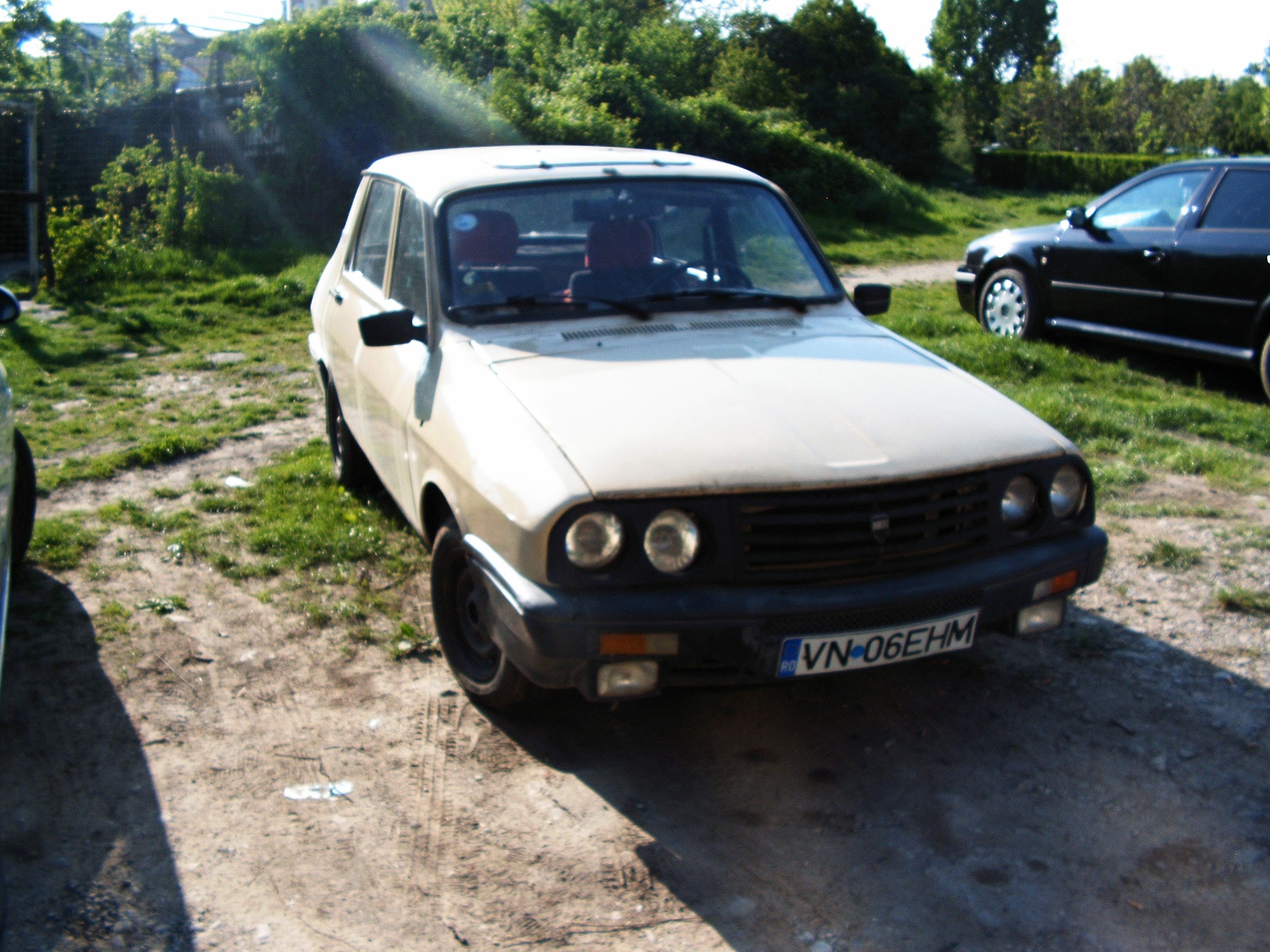
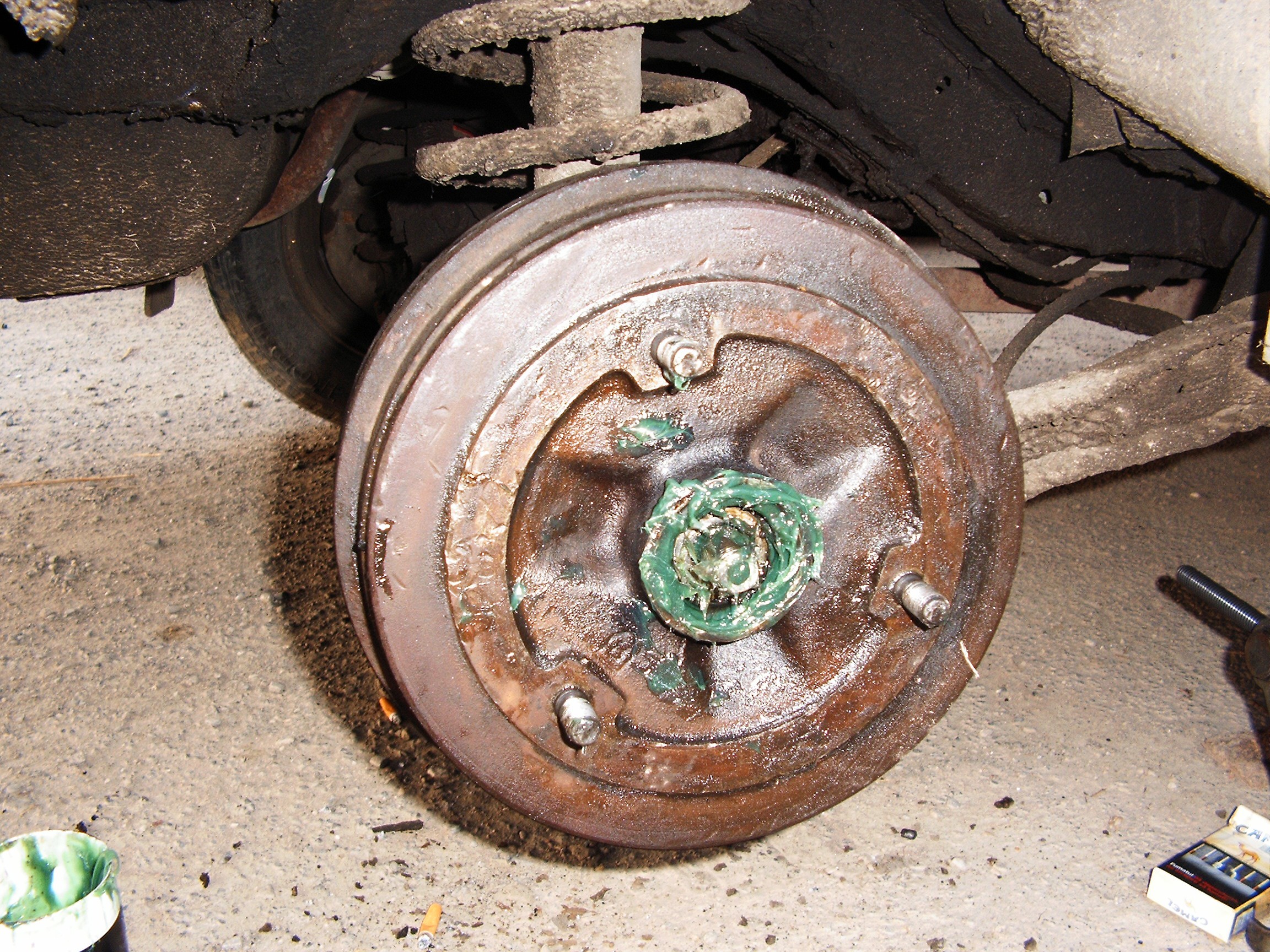
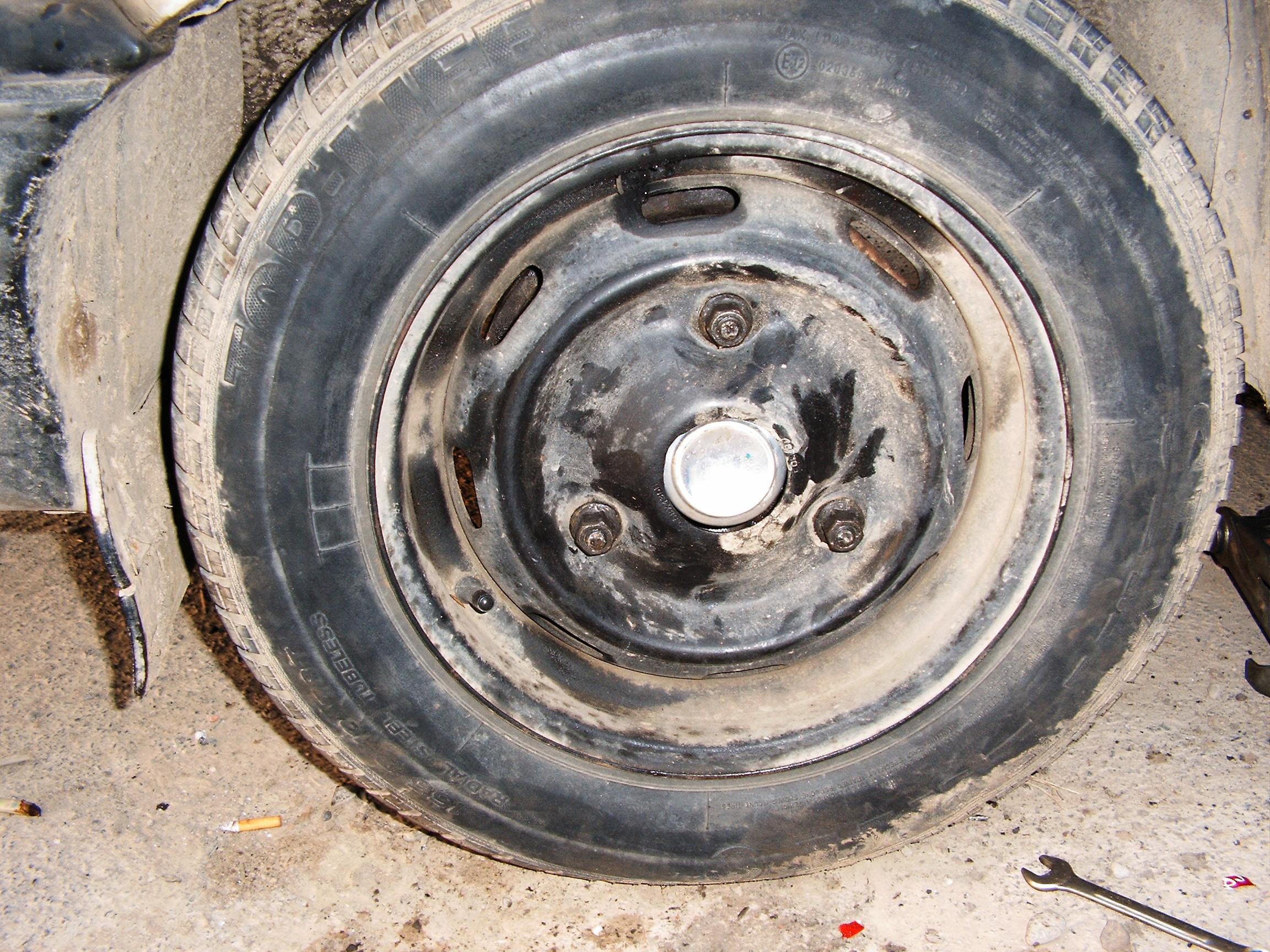
![]()
Look at it, it's so beautiful. And dirty above the lights due to vaseline. That's the first place where every Dacia 13x0/Renault 12 catches rust. And around the wind shield.
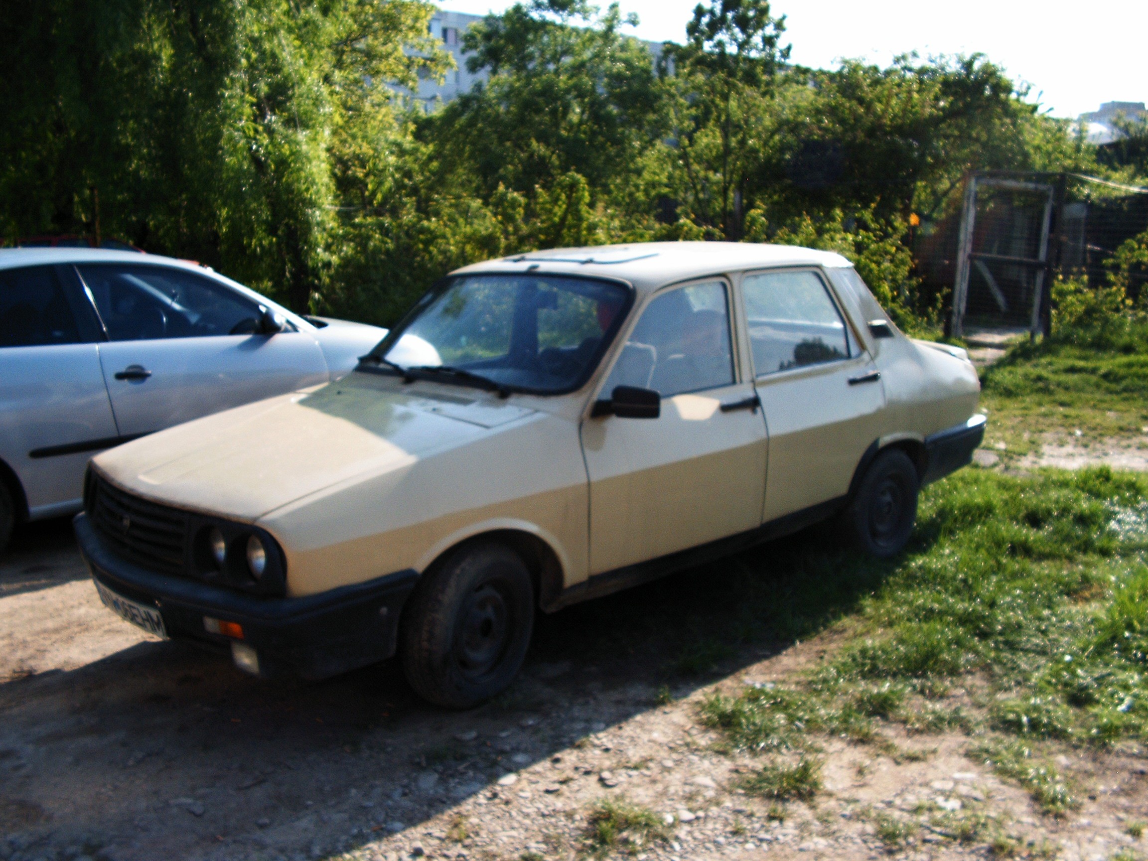
![]()
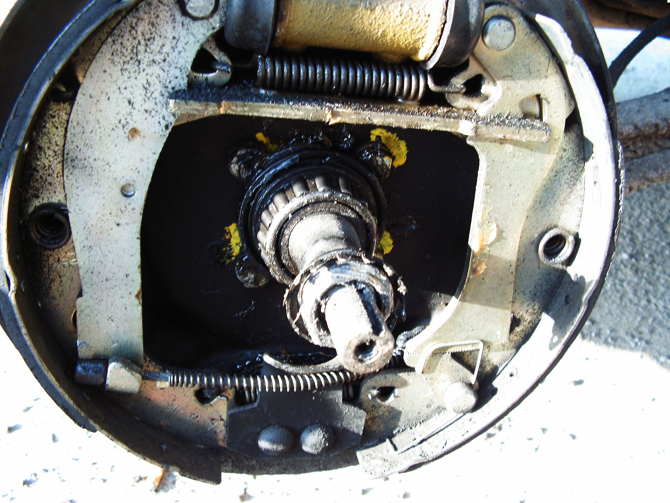
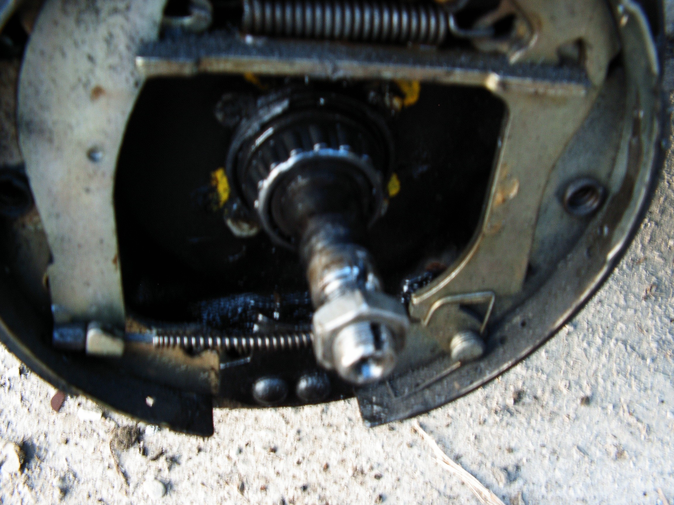
But unfortunately it is... sick. Limp wheel due to melt bearing. Let's see what happened.
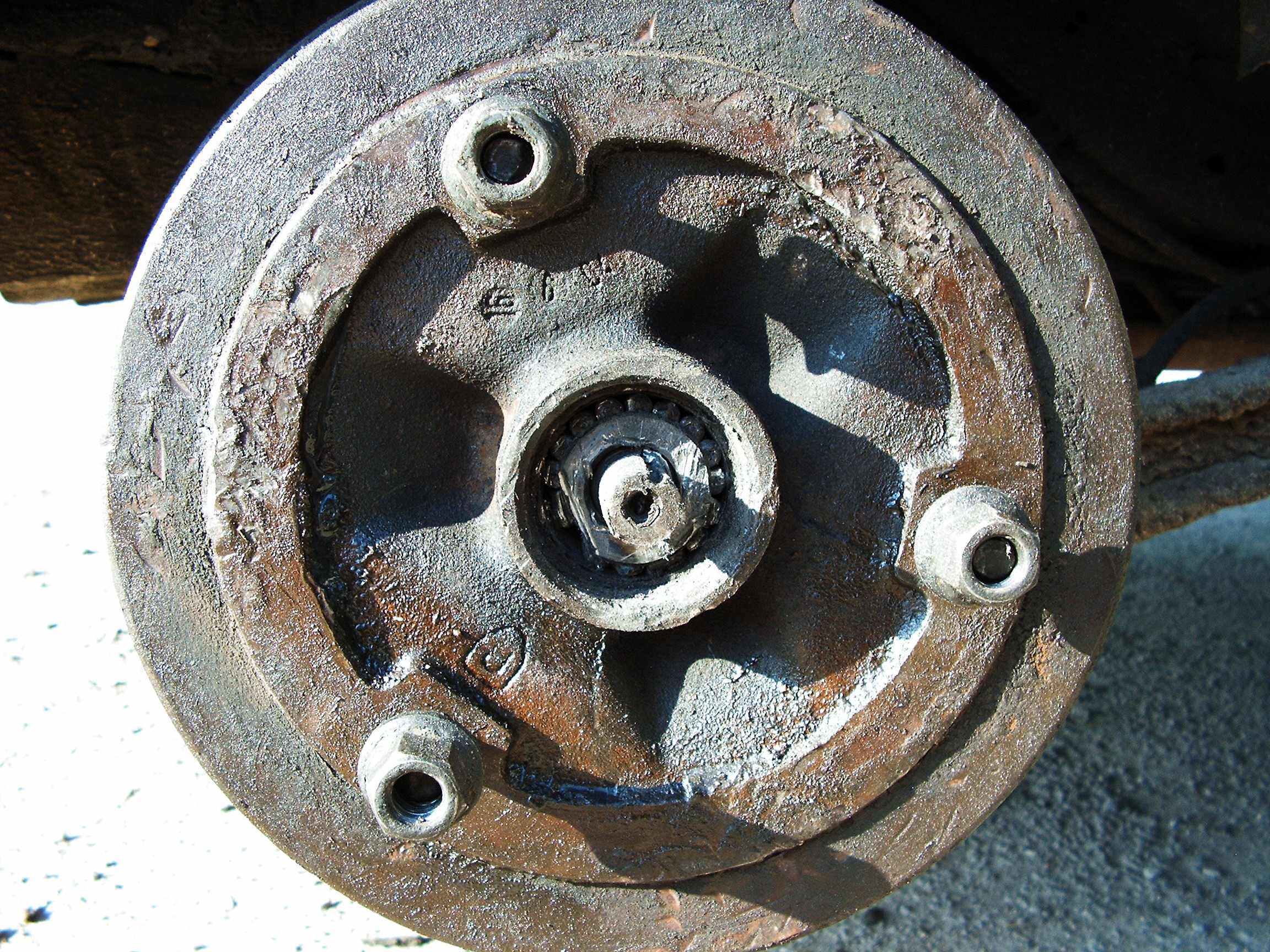
![]()
This bearing does not have round spheres, it has cylinders and it is pressed on a cone-shaped shaft. In the left side I tried to cut it using a huge hammer and a small tool I do not know how to name - after I payed a pot of money to some guy with a platform to carry me back home.
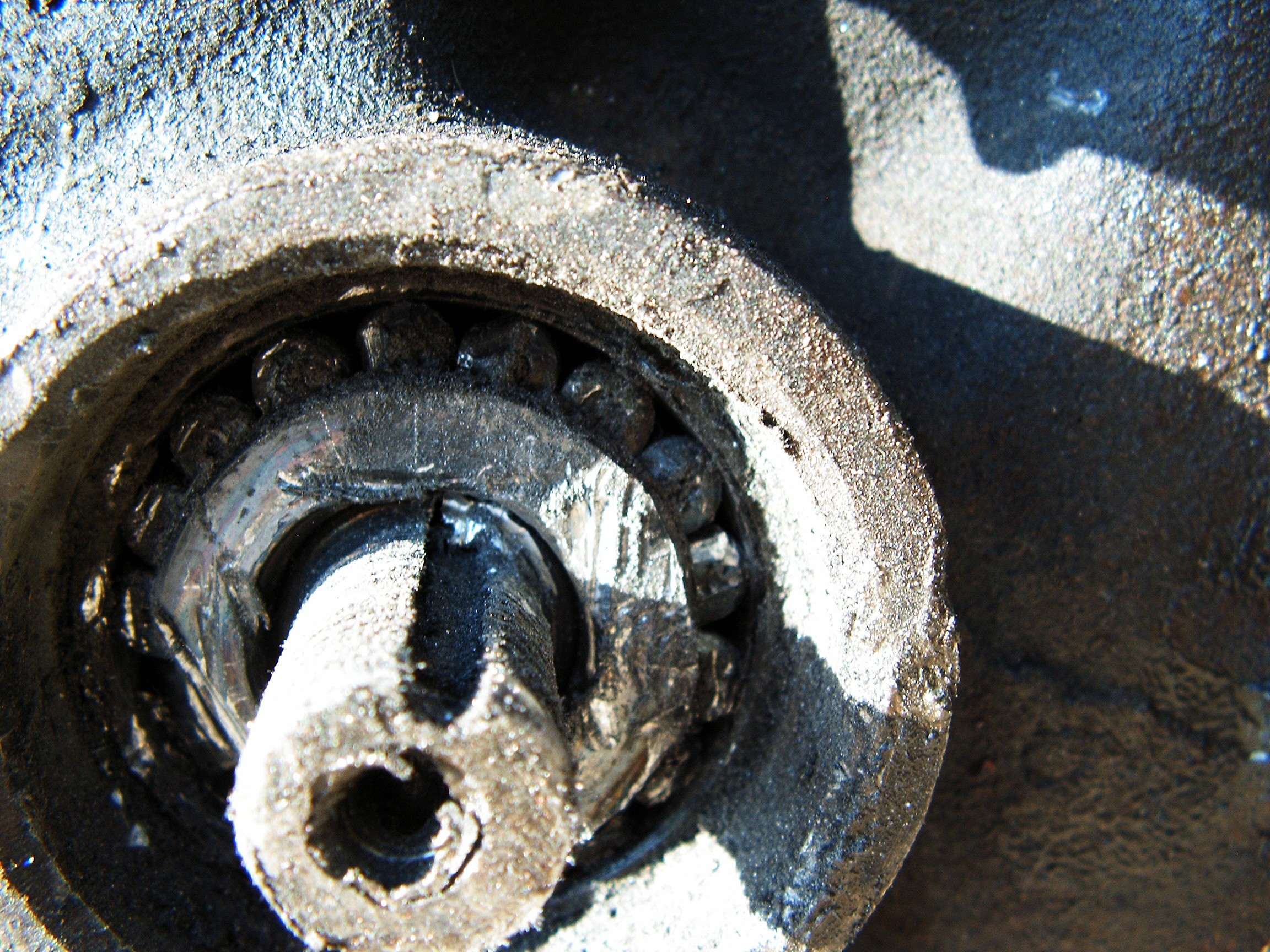
![]()
A repair on the road was not possible because I did not have the 220V converter installed. Also I could not prevent that due to the lack of training data for my Hardware Neural Network. Now tell me, mr. "mcnugget", is it really a good advice to ditch that neural network "crap"? I lost a lot of cash today for the platform. An early warning about suspicious vibrations can really save the day.
______________
The first hack I am going to present here is the Romanian Hacker's Chair. This subject was discussed sometime at the beginning of the Hacker's Channel.
![]() It is made from any automobile wheel....
It is made from any automobile wheel....![]() ...and the seat of a sidecar motorcycle. As oldest as possible. 1940s preferred, with their bad habit of marking their own territory with engine oil.
...and the seat of a sidecar motorcycle. As oldest as possible. 1940s preferred, with their bad habit of marking their own territory with engine oil.Extremely easy to build and very useful when solving bad situations to save funds.
The ingredients of the next hack are:![]()
- A small powered cheap dremel tool - German made;
- a ceramic disk;
- at least one beer;
- various dremel bits I am unable to name in English (no beer left after finishing the repairs);
- two cigarettes;
- a lighter;
- some WD-40 anti-rust spray, replace with hand cream or any cream that women use for the skin (lower results);
The goal is to cut the bearing base so the small cylinders can be taken out, the metal wheel removed and the bearing lower shaft to be also cut.
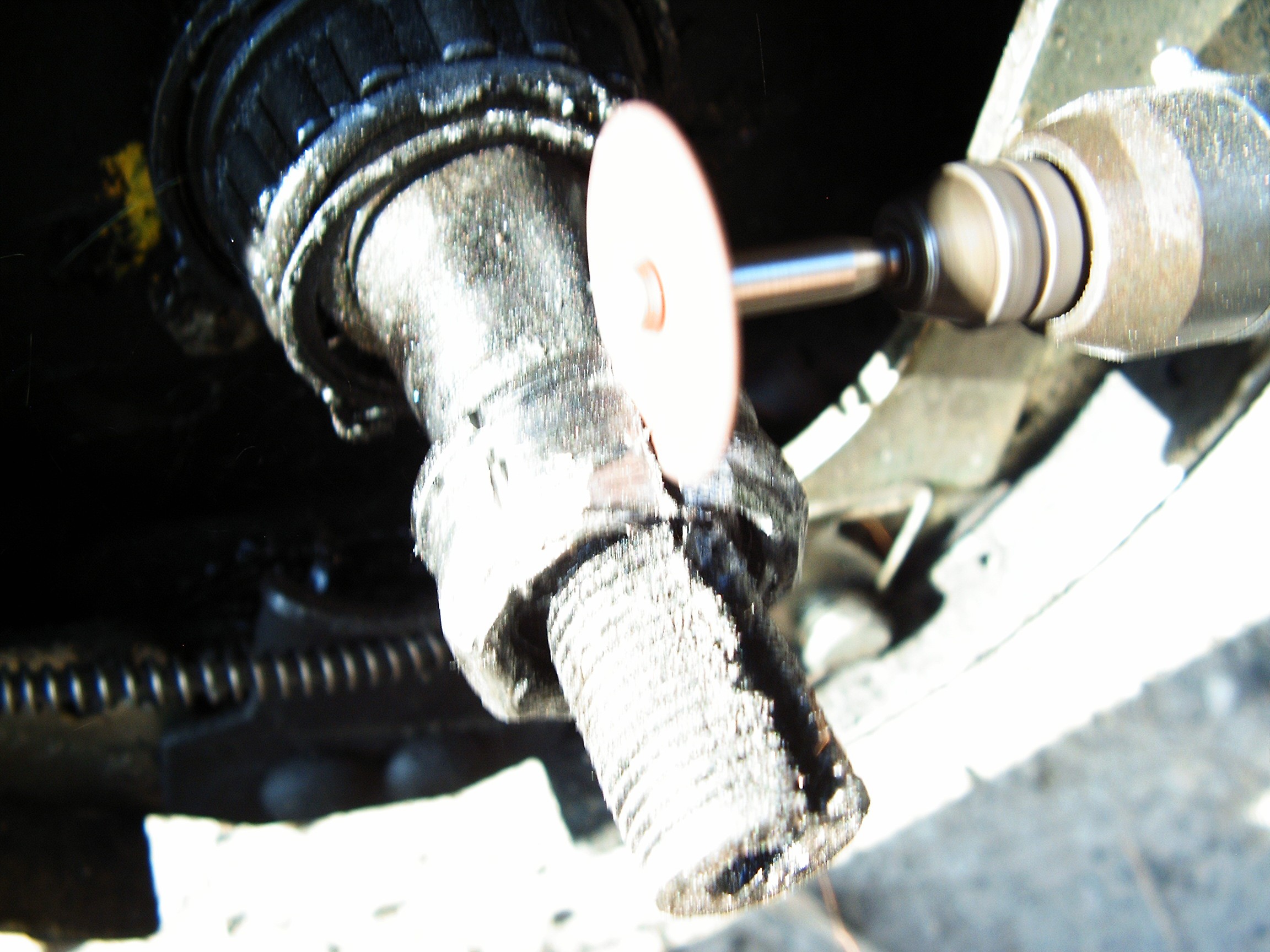
Due to the material of the bearing - hardened steel - it is impossible to cut it fast with such a tiny laboratory dremel tool. So this hack comes in handy:
![]()
The name of the beer becomes "Buffalo" in English translation. It's natural, no chemicals, no synthetics, perfect for the following hacking job:
Mix one part beer and one part WD40 anti-rust liquid from the spray.
Place fresh cigarette ash in this mixture until everything turns into some gray goo. Place some on the hardened steal piece, on the area you wish to cut into.
![]()
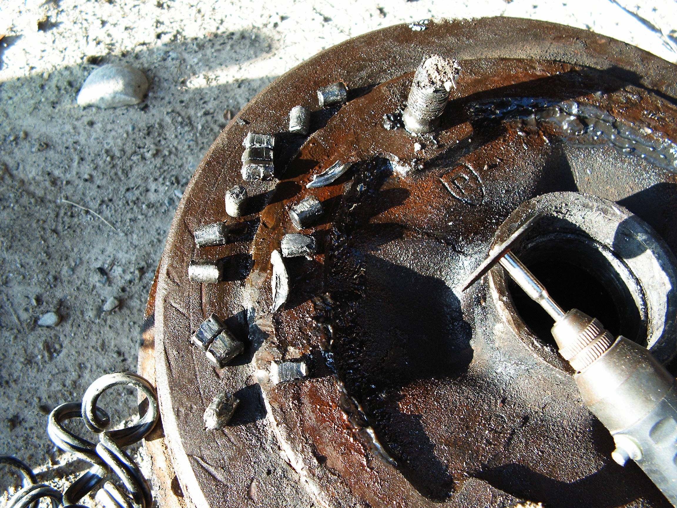
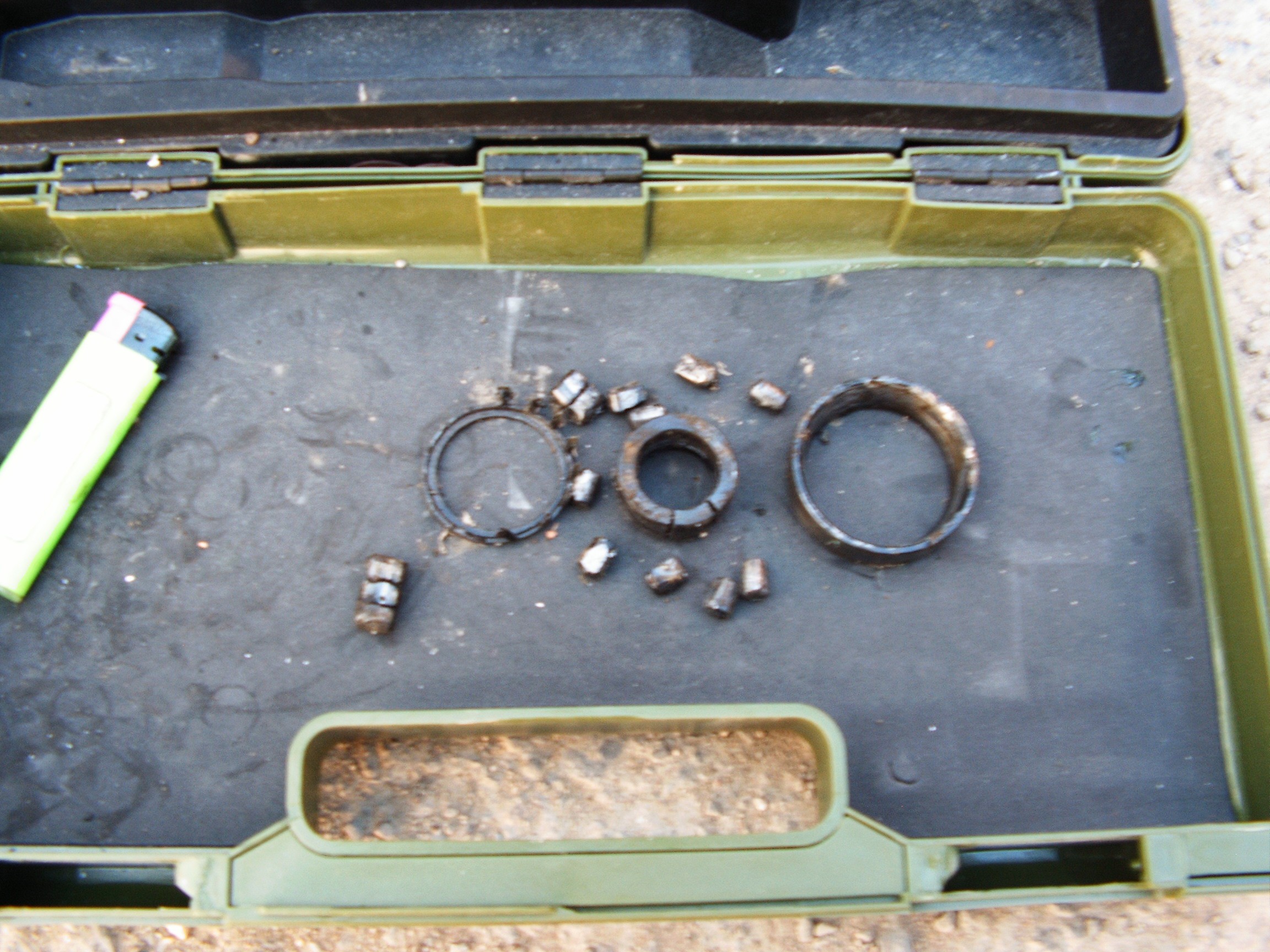
10 minutes and two cigarettes later.....
![]()
Melted cylinders came out from the bearing.
The magic potion allowed the dremel ceramic disk to cut the hardened steel like cutting into butter.
Remember that, one day it may become extremely useful.
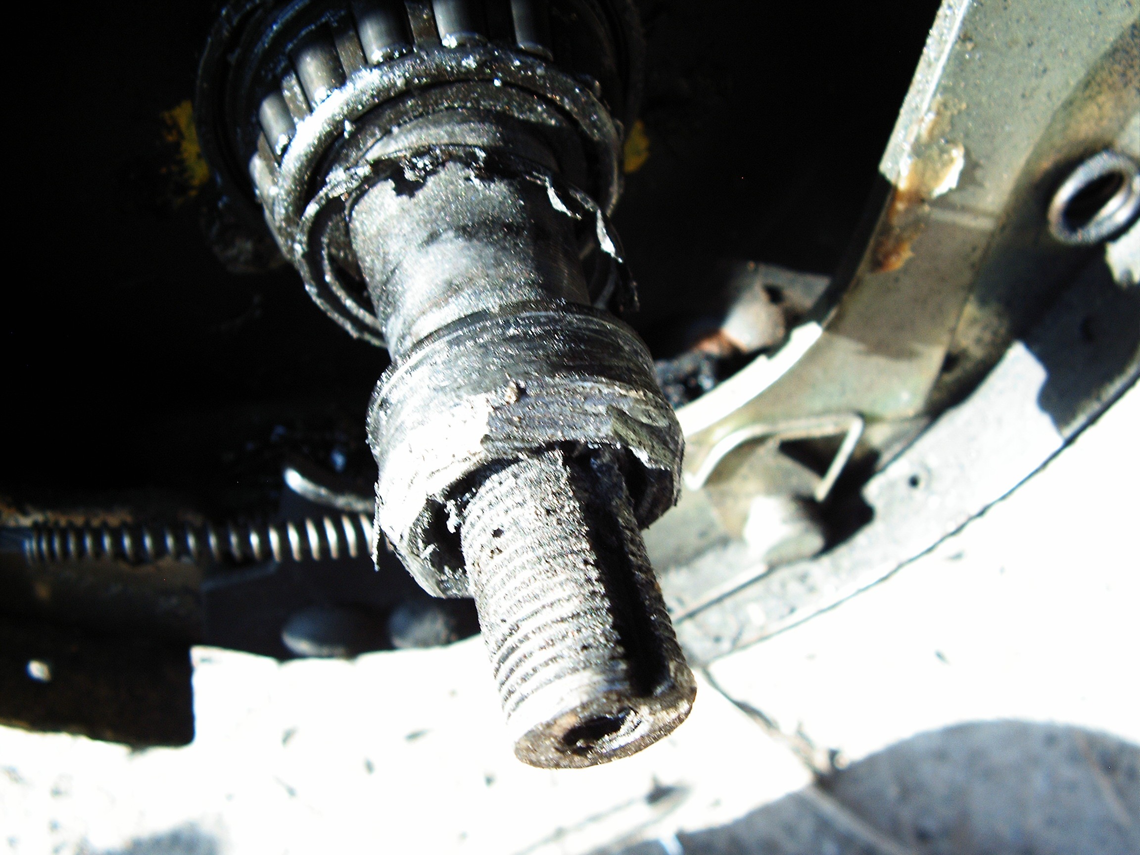
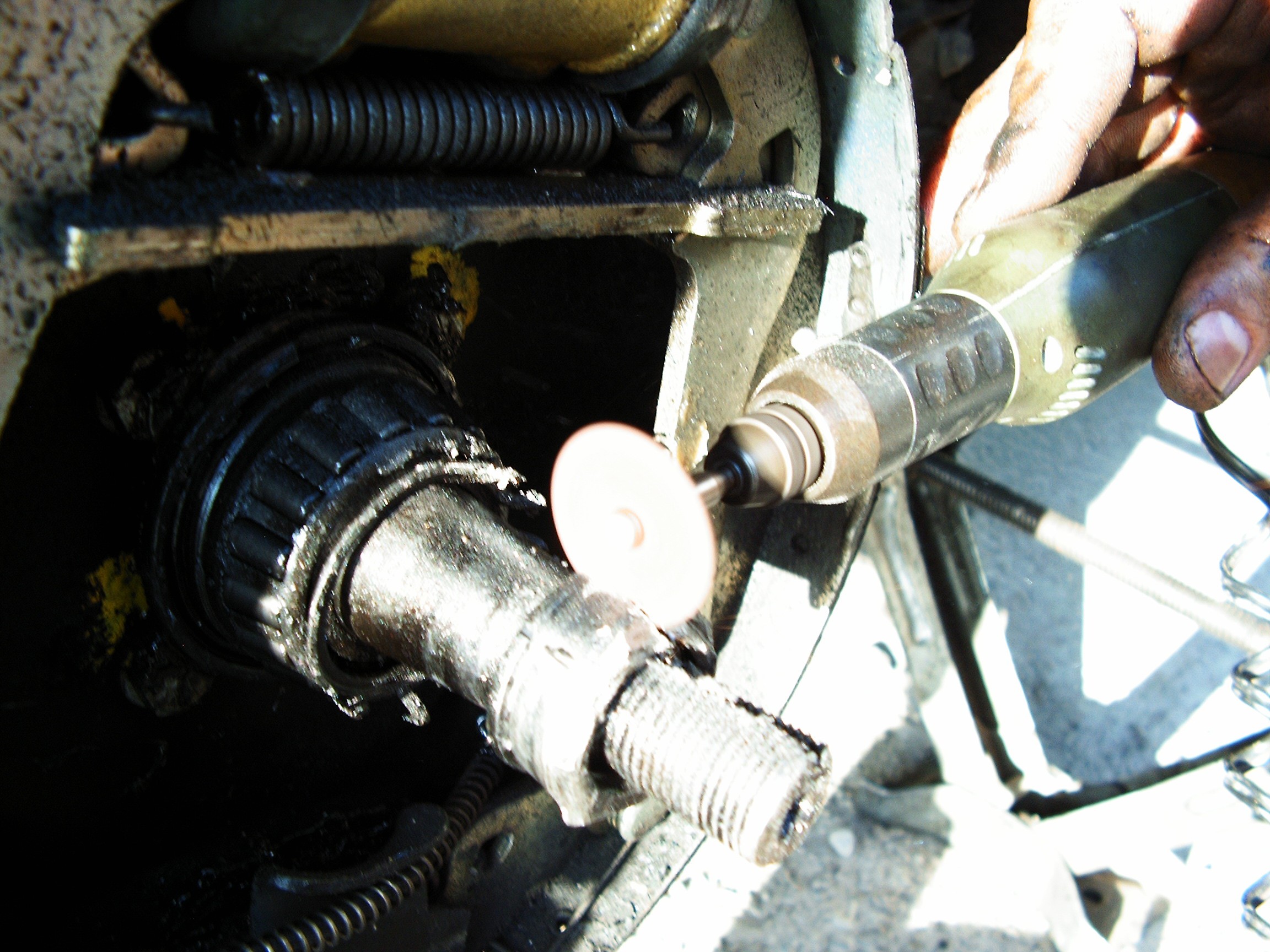
Now the bearing base on the shaft...
![]()
It is melted/welded. Preparing some more magic potion... need to go get more beer.
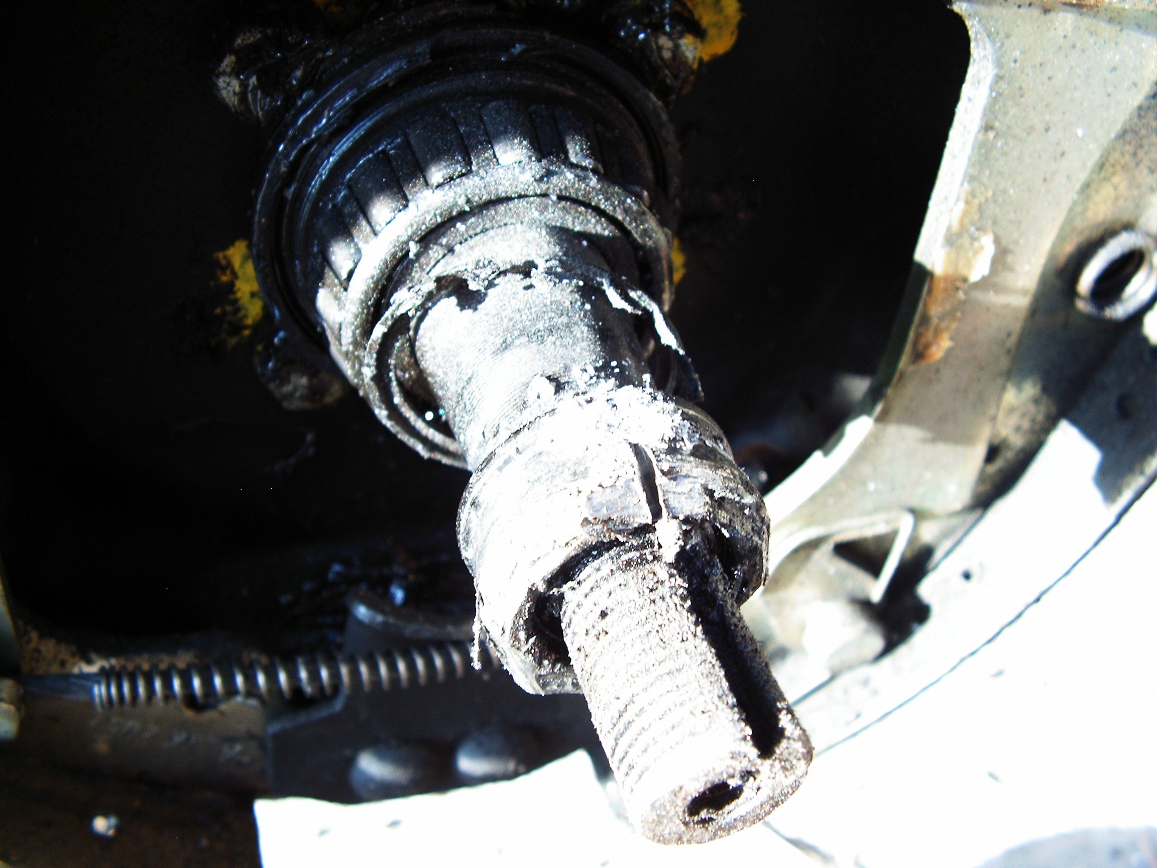
15 minutes, two beers... (I'm not encouraging people to smoke for scientific purposes so no more mention of that)
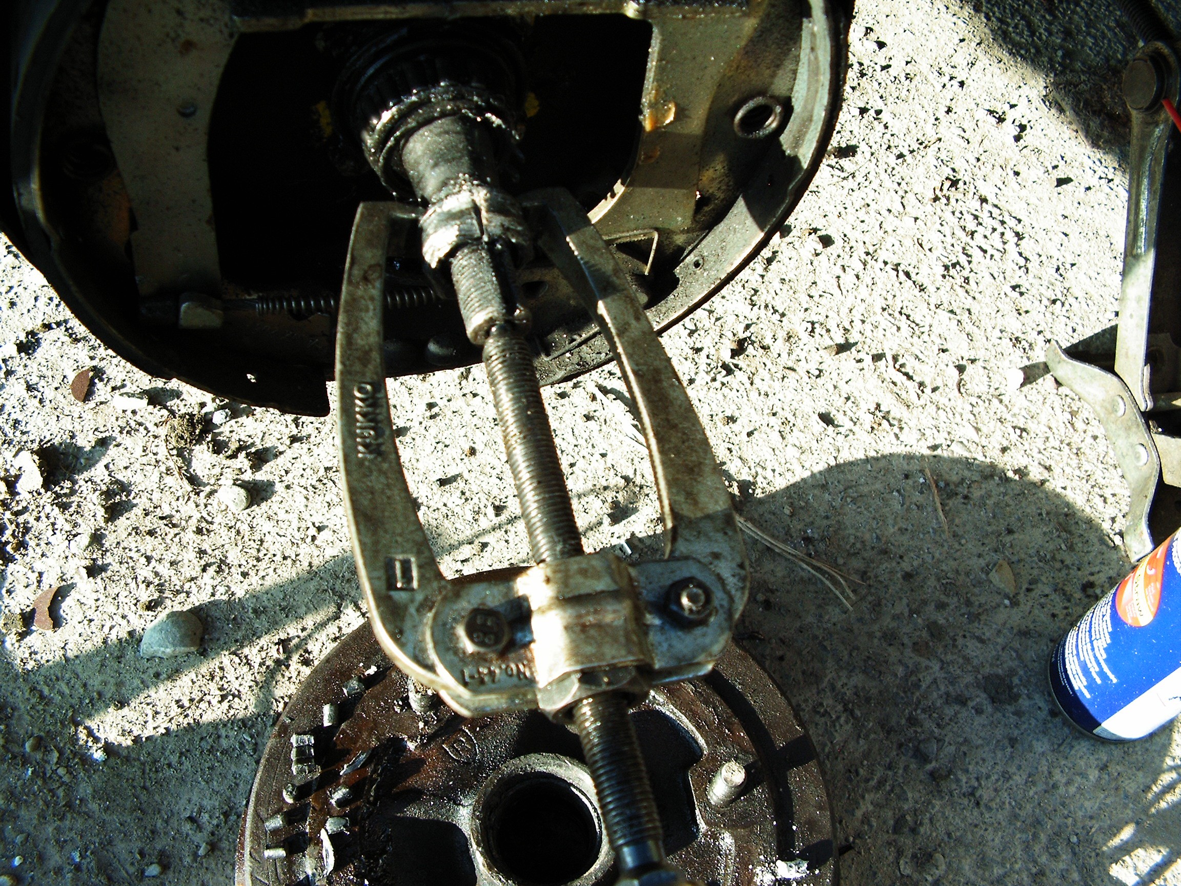
![]()
![]()
Bearing extractor is unable to handle the melted base. Need another cut and one more beer.
![]()
![]()
![]()
Another 10 minutes of work, some help from a big hammer and the bearing extractor is able to complete the job it's supposed to do.
Spare bearing found in the trunk - it's amazing what you can find inside an old Dacia, this old lady is full of surprises.
![]()
Two hours later I managed to reconstruct the beginning of the shaft screw thread using the same small ceramic disk and the dremel.
![]()
Finally I put everything back together. Vaseline, new bearing, screw nut and safety pins. It's getting dark and cold. Beer reserves getting low.
![]()
The repair is not completed without the last hack: Vaseline cover made of the bottom side of a beer can. That thing is supposed to keep the vaseline inside while I drive the car to service.
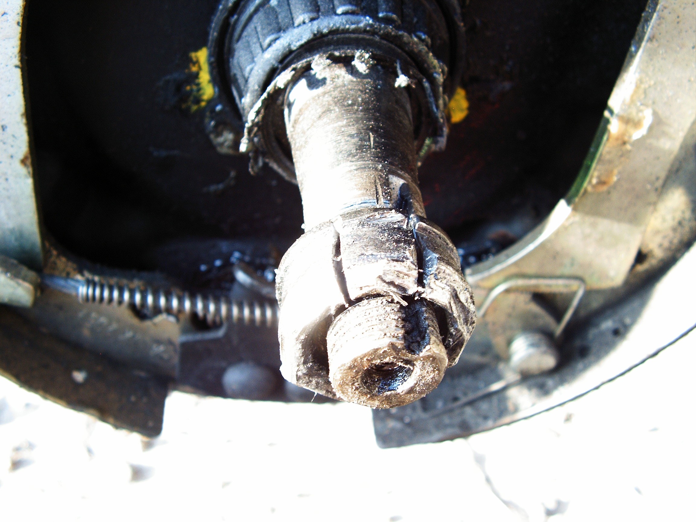
Because the bearing welded on the shaft, the conic share (diameter) is likely to be compromised. Unable to state this sentence with proper English. Combining these hacks I will be able to drive to service without calling for another platform, so I saved around US$100. The shaft is part of the rear axle and it cannot be replaced. I will need a new rear axle... or a recycled one.
Here is the compromised bearing, which arrived here with the greatest love from some no-name Chinese manufacturer:
![]()
So tomorrow it is Sunday and I will drive everyone crazy with phone calls asking for another huge rusty piece of iron.
Happy Hacking.
I'm out for a fresh cold beer - hacker's CPU coolant liquid.
[END OF TRANSMISSION]______________________________________
kernel panic: improbability coefficient below zero
Retro-futuristic automobile control panel
Conversion of dashboard from an old, Communist clone of the French Renault 12 (Dacia 1310)


 Left side: the old version casing with more warning lights than the newer version. Last version had only two gauges - gasoline and speed. I need the precision of the last version dials but I want to know as much information as possible about the engine.
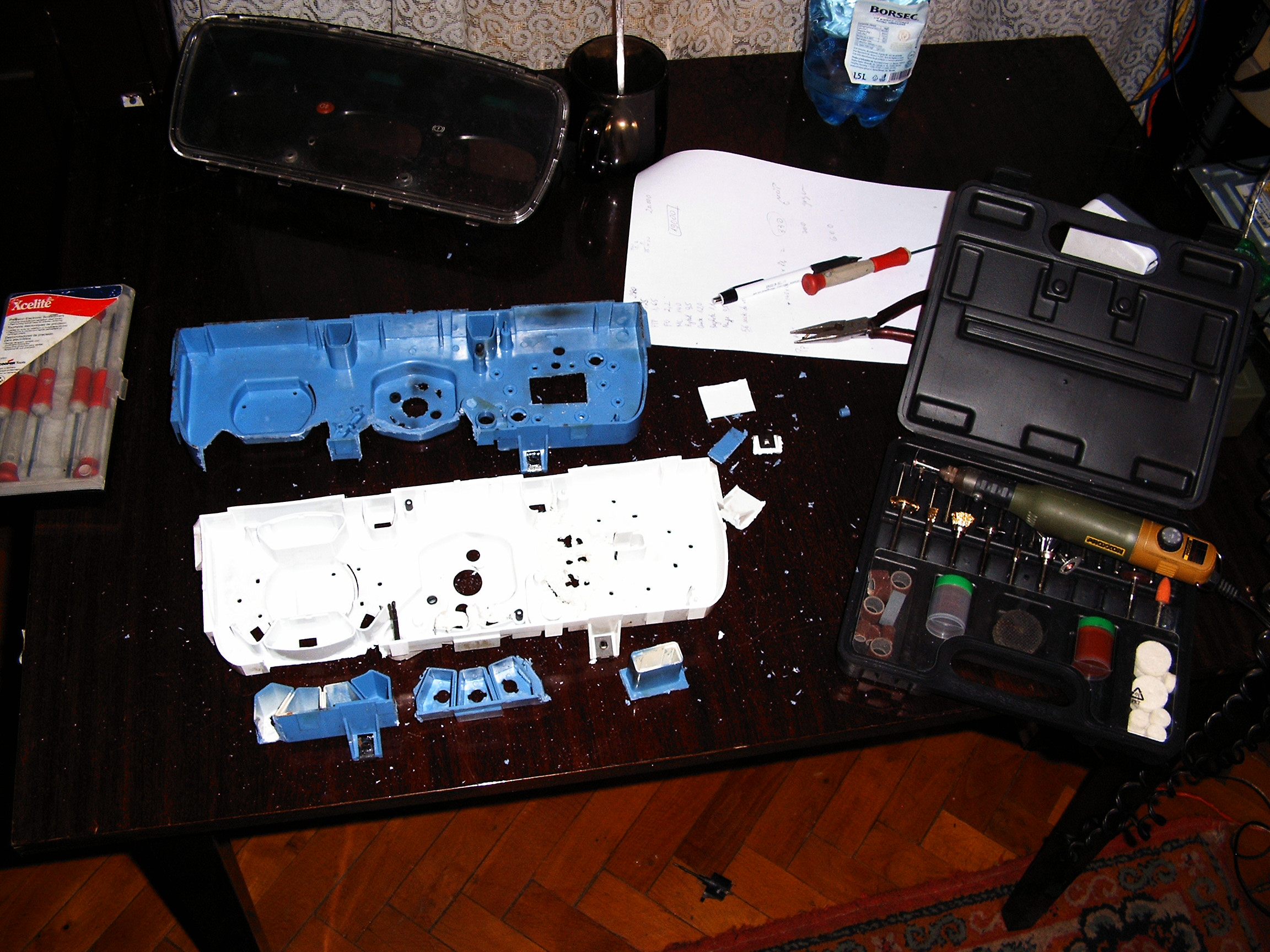
 The aluminum pointers were removed and the new pointers were fixed using Super Glue and a lot of patience. Adjusting weights for was done for each of the 6 small gauges.
 Adjusting the balance was performed with the dremel tool by cuting small pieces of plastic from the pointer.
 And It looks better in reality.
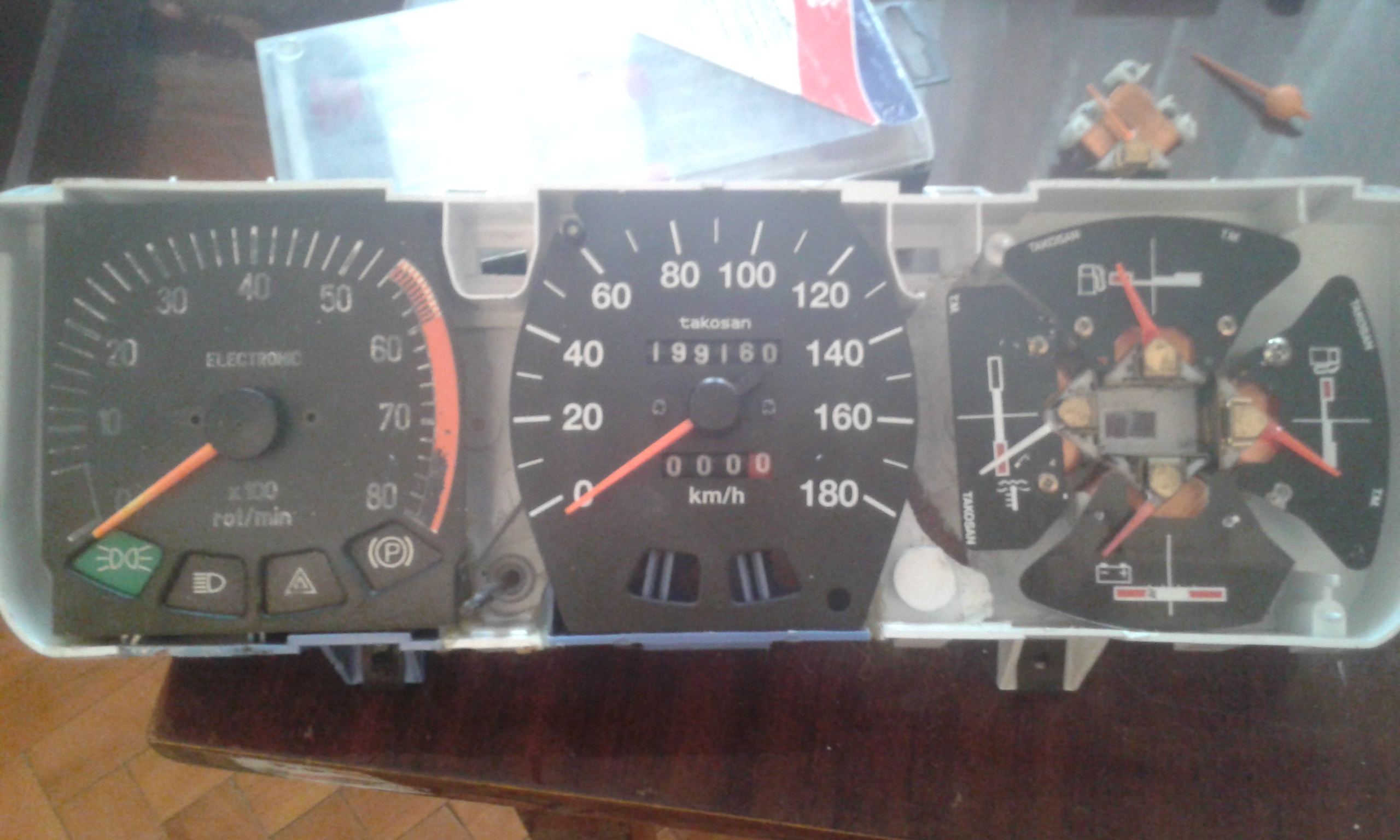
 This is without background LED controls.
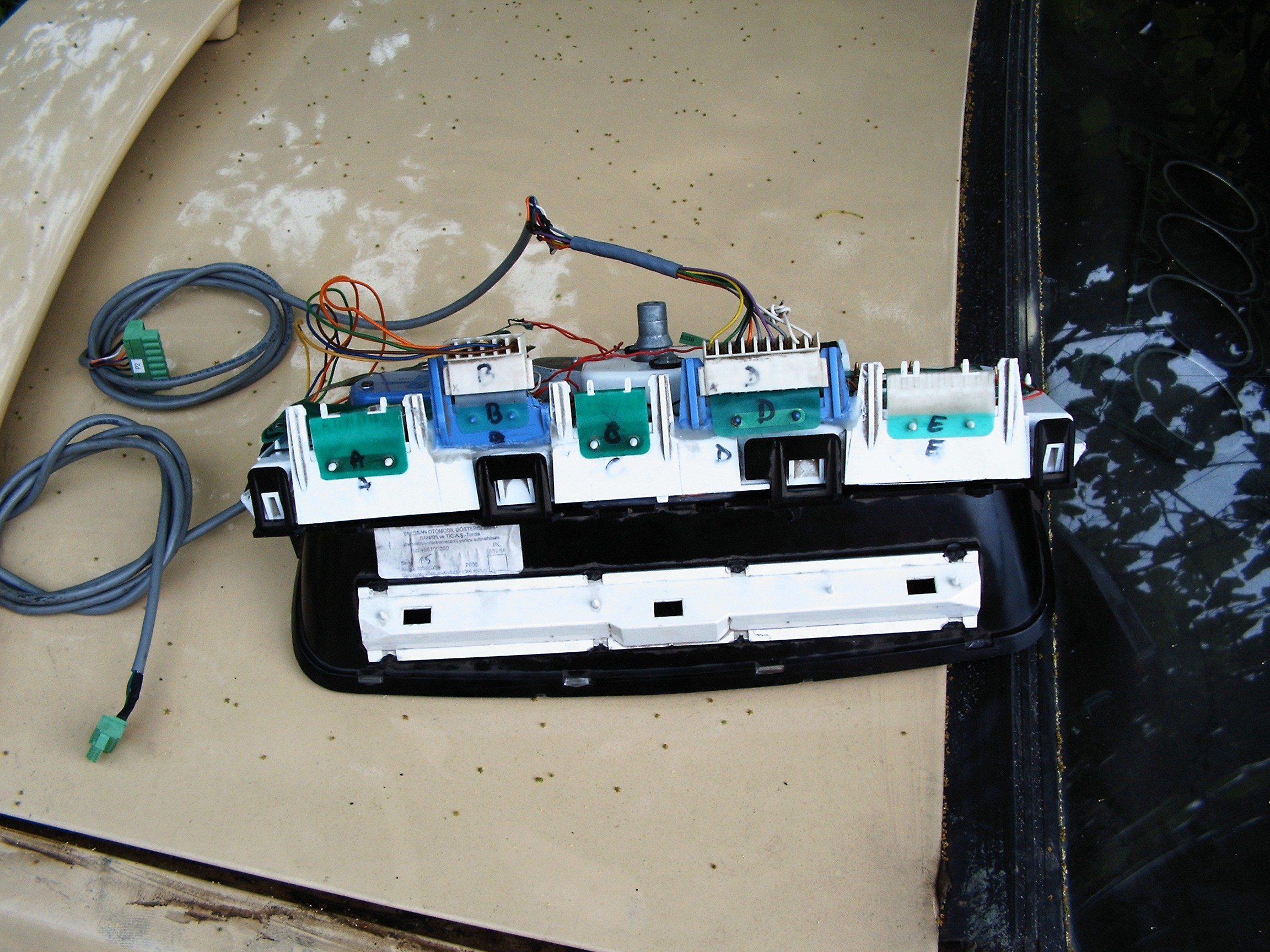
 Somehow I managed to modify the back flexible PCB according to the schematic above.
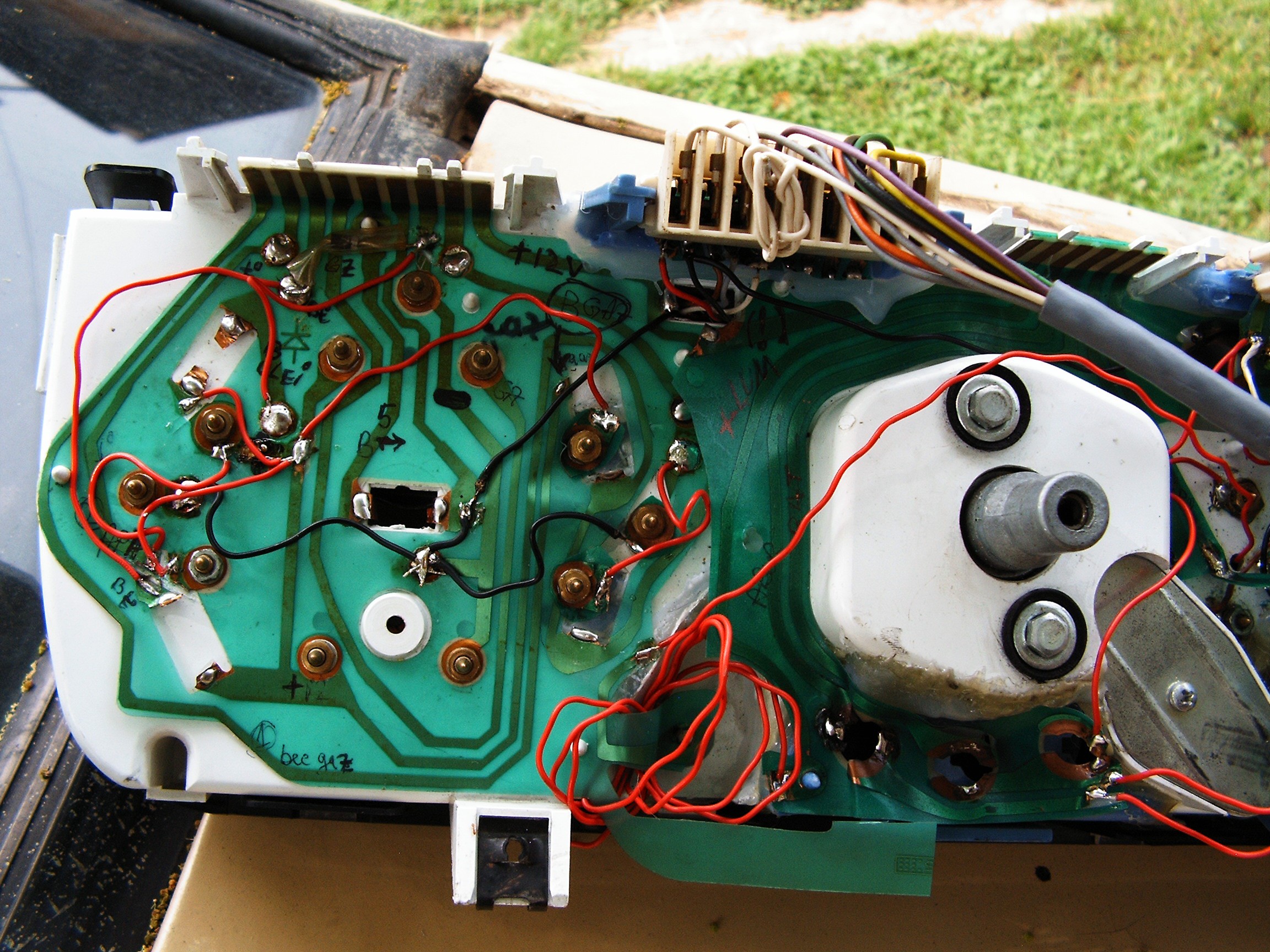
 from left: detection tube, then a 6J1J lateral contacts, pass-through-hole pentode, and two 6J45B subminiature tubes. There is also a long long 4.6GigaOhms resistor, I will try to make a closer photo of that.
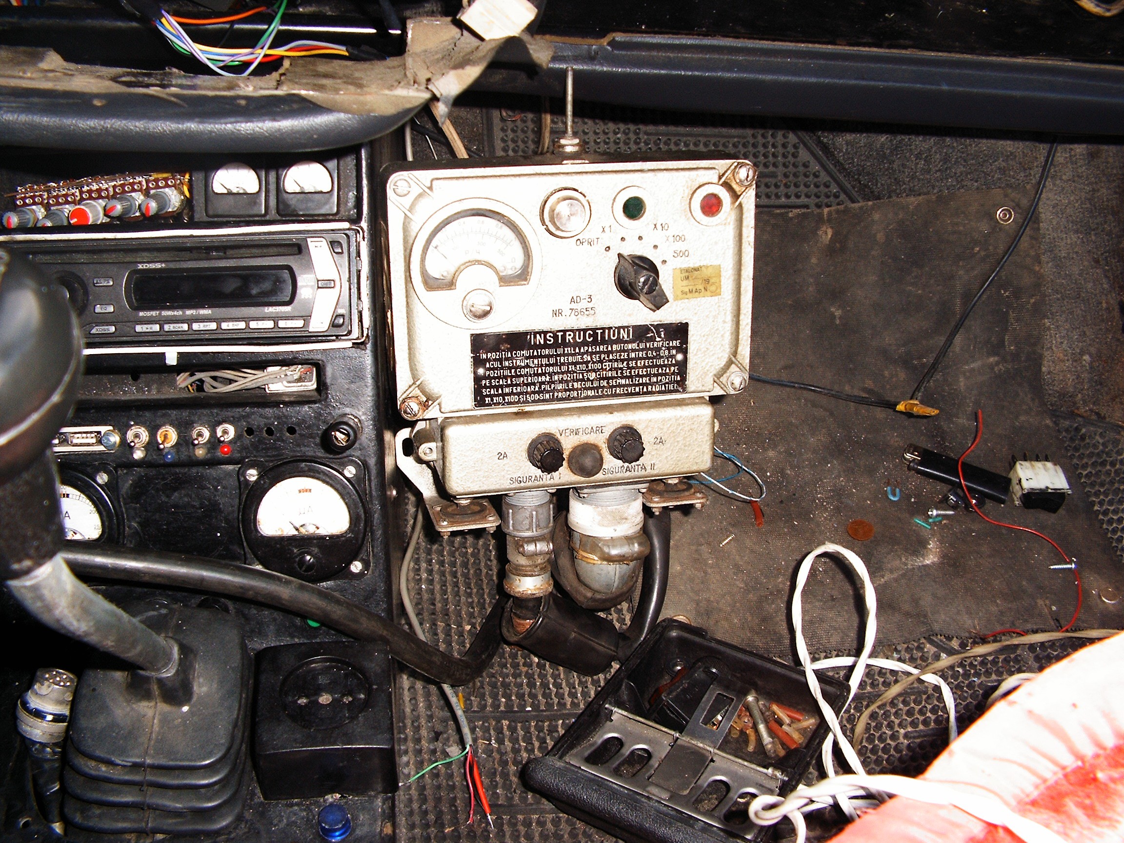
 "Nivel" means "level".
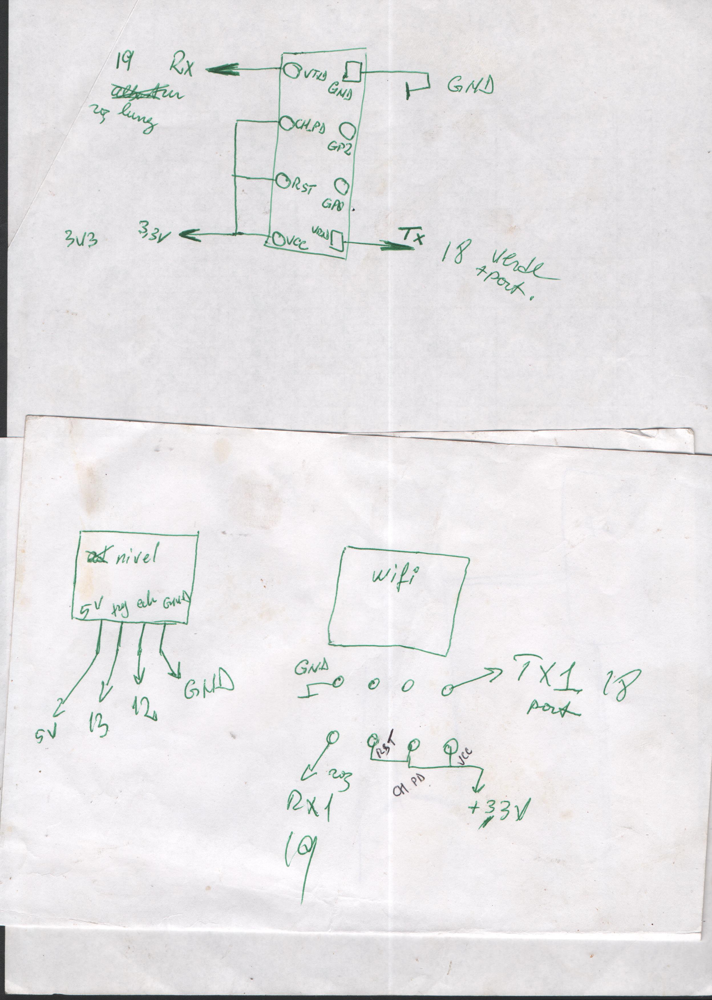
 Then, a cable plastic coating applied on top of the soldering. While driving, the wires vibrate and move. The soldered area is hard, the rest of the cable is soft. After years of repeated process, the area at the start of soldering... will begin to break and the cable will become interrupted. So this little hack keeps the vibrations away from the problematic area.
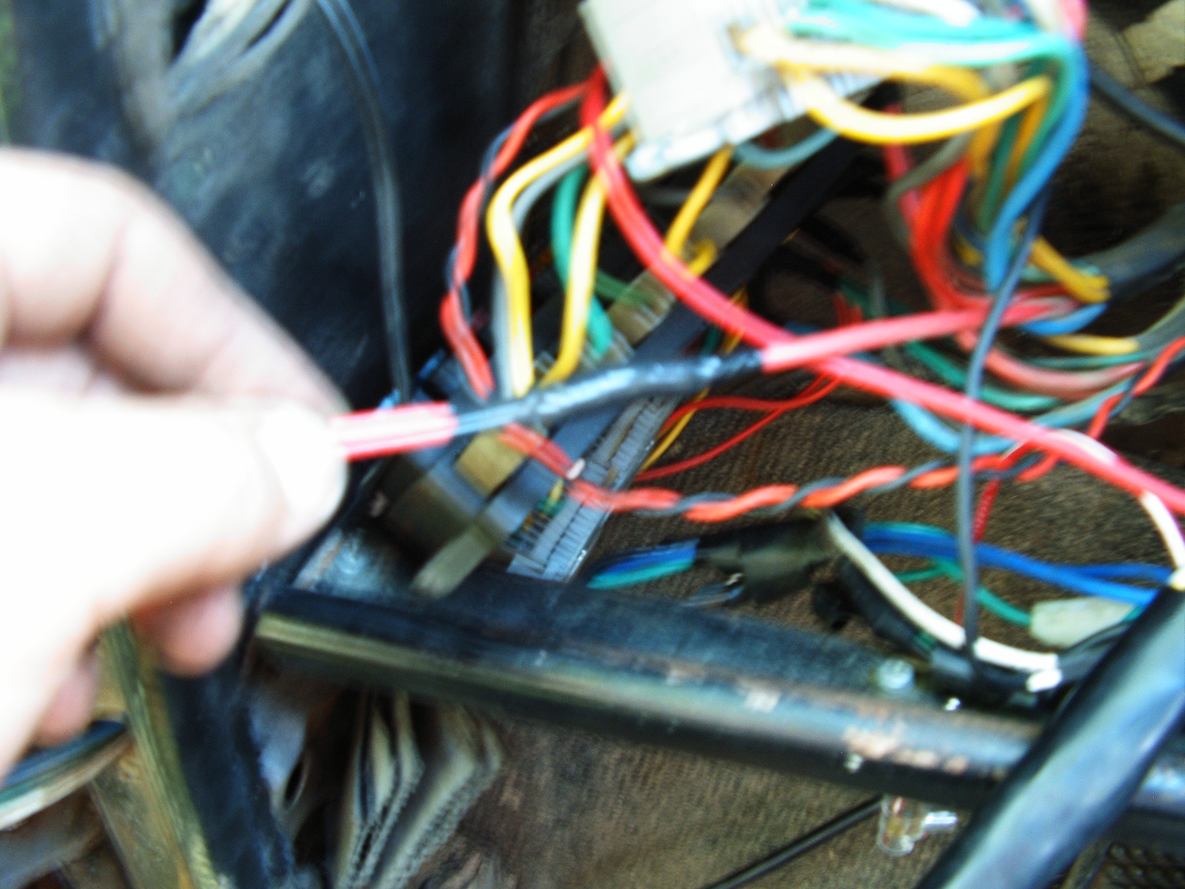
 It is made from any automobile wheel....
 ...and the seat of a sidecar motorcycle. As oldest as possible. 1940s preferred, with their bad habit of marking their own territory with engine oil.