 [skaarj]
-
Project published on Hackaday blog and selected among 20 first round winners
04/20/2016 at 12:11 • 1 commentDear hackaday.com editors,
Thank you very much for publishing my project.
It is a great honor.
Dear judges,You gave me a greater honor for selecting it among the 20 winners of the first round.
I promise I will not let you down. Question is... will you?
______________________________________
kernel panic: improbability coefficient below zero
-
CAN-BUS REDUX
04/19/2016 at 13:39 • 0 commentsCan-Bus redone with some old-school engineering
Key words: another concept design.
The car is back, the rain is washing it for around two weeks and it will keep doing that until frogs will appear everywhere. So no useful pictures. The car is dirty again - some thin layer of orange goo. At the TV they say it's sand from Sahara. Looking on hackaday prize projects, it seems people are more interested in stationary toys, flying toys and portable game toys - which will eventually solve dust gathering problems in the near future, so let's jump deep into the rabbit hole.
It's time for some serious stuff - computing system architecture:
![]()
According to the figure, the engine and the wheel mechanics under the car are monitored (through some sensors/transducers) by the Arduino, which outputs some signals to the gauges (lights and data), and to the RasPI by means of SerialUSB() encoded strings. In the drawing there's just one Arduino but there may be more - depending on the development process.
To keep things in order and to allow further development without any major headaches, here's how to do it:
- option 1: implement modern automobile standards and throw away pots of money for undocumented sensors, interfaces, central control units, meaning no more retro approach and money thrown through the window;
- option 2: (re)engineer some new standard using old-school methods still widely used today.
First, a little history lesson:
To get things done quickly, the petroleum industry engineered a great tool called Well-site Information Transfer Specification which is a communications format used for the transfer of a wide variety of well-site data from one computer system to another. This was engineered back in the days when every byte of memory was so expansive that everybody felt comfortable with just 640 kilobytes of RAM. This transfer format is still widely used to exchange data between various types of petroleum drilling equipment, and from what I learned at my work place, this was first used in drilling equipment which were sent to the moon surface.
This format is based on plain text data, something like this:
13100400[.00]!!
13130200[.00]!!
First two chars (13) is the category of the measurement (in this case, chromatography gases)Next two chars - methane (10) or ethane (13)
next four - the value in PPM
things between square brackets: optional decimal point + decimals
"!!" - end of string
So some equipment wishes to say: Look, I want to send you CHROMATOGRAPH data - methane 400 PPM and ethane 200 PPM. I also wish to inform you that current depth is 5000 feet, the temperature in the bottom of the hole is 160 degree F, we record increased gas levels, some vibrations, increased pressure and it is possible from the calculations that the well will erupt.
Something like that.
It is documented here - see the tables.
This is widely used even today, as there are a lot of equipment built many years ago - and they were built to last forever. It is simple, easy to extend for new categories and data and it is compatible with most of the systems on the market. At work place we even have computers with 80486 processors, running various well drilling monitoring applications with help from some sort of an old Unix, upgraded to 32 megabytes RAM and they still work perfect with no flaws.
WITS negative issues:
- unable to send negative numeric data;
- unable to send more than 2 decimals after digit point;
- it is scaled to be handled by old tech systems with small amount of memory, so special care should be taken when implementing on modern systems to keep things compatible.
And many more, which the contract from my work place forbids me to disclose.
To get things done, the arduino must generate a string which looks like a bunch of chained hot-dogs and send them to the RasPI in order for it to process, log, remote monitor and perform other operations.If more Arduinos are desirable, then they can be easily interfaced without any further modifications to the software. Just an USB hub plus some ftdi converters.
For example, my AI-based vibration processor can easily encode the vibrations into such a WITS-based string using the PIC16F84 present on the board. This can also be handled by some small tiny memory microcontrollers which could be incorporated in later sensors.
At this time, the tables below are incomplete but expandable to whatever fits the needs of the project.
The proposed syntax looks like this:
"CONTROL>hotdog1>hotdog2>hotdog3!!\n"
The "hotdogs" are separated with ">" sign, then there's "end-of-string" from the original WITS and a new line at the end.
X>AAAA>BBBB>CCCC!!"Hotdogs" explained:
X - control (bool) - is this parameter currently under manual adjustment? (0/1)
A - unit category
B - unit position
C - unit value
!! - end of string
CATEGORY 0000 - Computer (rasPI+monitor) power controls
Position Value 0000 (relay 0) 0 (off), 1 (on) 0001 (relay 1) 0 (off), 1 (on) CATEGORY 0001 - measurements
Position Value 0000 (gasoline level) 0 -> 4096; 0001 (engine core temperature) 0 -> 4096; 0002 (battery level) 0 -> 4096; 0003 (engine core pressure) 0 -> 4096; 0004 (speed - km/h) 0 -> 4096; 0005 (RPM) 0 -> 4096; 0006 (rads, REM/s) 0 -> 4096; 0007 (batt charging, amps) 0 -> 4096; 0008 (gasoline consumption liter per min) 0009 (gasoline instant consumption milliliters/s) CAT 0002 manual input states (boolean)
POSITION VALUE (bool) 0000 (visibility lights, just to be noticed) 0 / 1 0001 (short range lights) 0 / 1 0002 (long range lights) 0 / 1 0003 (rear fog lights) 0 / 1 0004 (front fog lights - projectors) 0 / 1 0005 (direction signal) 0 / 1 0006 (foot brake) 0 / 1 0007 (manual brake) 0 / 1 0008 (belt 1) 0 / 1 0009 (seat 1) 0 / 1 000A (belt 2) 0 / 1 000B (seat 2) 0 / 1 000C (belt 3) 0 / 1 000D (seat 3) 0 / 1 000E (belt 4) 0 / 1
CAT 0003 automatic warning states (problems signaled by sensors)0010 (belt 5) 0 / 1 0011 (seat 5) 0 / 1 0012 (front left door) 0 / 1 0013 (front right door) 0 / 1 0014 (rear left door) 0 / 1 0015 (rear right door) 0 / 1 0016 (trunk) (boolean values) errors that can be provided by car internals; lights, windshield wiper engine fault, electric window
CATEGORY 0004 - ambient parametersPOSITION VALUE (bool) 0000 (low fuel alarm) 0/1 0001 (overheat alarm) 0/1 0002 (low pressure alarm) 0/1 0003 (vent engine alarm) 0/1 0004 (?) 0/1 POSITION VALUE 0001 power-state 0/1 0002 back light dial - gas gauge 0-4096 0003 pointer light - gas gauge 0-4096 0004 back light dial - oil pressure gauge 0-4096 0005 pointer light - oil pressure gauge 0-4096 0006 back light dial - battery level gauge 0-4096 0007 pointer light - battery level gauge 0-4096 0008 back light dial - engine core temp gauge 0-4096 0009 pointer light - engine core temp gauge 0-4096 000A back light dial - speed gauge 0-4096 000B pointer light - speed gauge 0-4096 000C back light dial - RPM gauge 0-4096 000D pointer light - RPM gauge 0-4096 000E pointer light - radiation gauge 0-4096 000F pointer light - charger gauge 0-4096 CAT0005 - to be determined
Following the above tables, when the Arduino sends engine core temperature to RasPi (in order to print it on screen/draw a diagram in some Alien:Isolation retro style), the encoding string looks like this:
0>0001>0001>2048!!
first 0 - this measurement is not under manual calibration (raw data)
0001 -> measurement parameter
next 0001 -> engine core temperature
2048 ( half of dial) - meaning around 40 degree Celsius, temperature too low according to engine manufacturer, so the car should stay still until the temperature reaches 90 degree Celsius - recommended temperature for this type of engine.
__________________
1>0004>000A>0001!!
1 -> unit current in manual calibration mode (adjusting from Arduino Rotary Encoder)
0004 -> ambient parameter
000A - speed gauge back light
0001 - one unit above lower limit of 0...4096 interval, meaning there's no backlight set.
________________________
0>0001>0009>001F!!
0 -> raw data (not under current manual calibration)
0001 -> measurement parameters
0009 -> gasoline instant consumption milliliters/s
001F -> hexadecimal value (31 milliliters/second)
!! -> end of string
________________________
I hope you can follow the logic.
The receiving software (RasPI side) is based on fixed length string processing. Also old-school stuff.
The software implementation of this proposed old-school standard is now work in progress.Since I do not have any GitHub account and I don't need any (I can barely handle my bank account which is empty most of the time), I will just paste them here when they are finished and when they prove their use.
Next update in the weekend.
In the mean time I must find a new place to build a proper lab. This project requires a lot of attention and it can't be done entirely from home.
[END OF TRANSMISSION]
______________________________________
kernel panic: improbability coefficient below zero
-
SCIENCE TIME (II) - How about reducing the pollution of an ignition-based engine?
04/09/2016 at 15:54 • 0 commentsSince it rained a lot this week, the painting is not yet ready due to the humidity in the air. I did not want to risk anything because the repaint was not performed in an enclosed space.
So back to science time. First, I am not going to include in this project any hydrogen source powered from the normal power grid. But I'm thinking to combine such a hydrogen electrolysis device powered by a big solar panel. I still have all the system gathering dust in some basement so there's no big deal about this - except buying a huge solar panel.
In the first part I presented the vibration diagnosis of engine block, for such a piece of technology running on hydrogen as fuel. Also I talked about some modifications performed to the (former trash dump) automobile engine which resulted in some bad side effects both for the mechanism and the pets in the neighborhood.
The second scientific article rejected by certain respectable journals in the academic neighborhood is about applying some unconventional technology to combustion engines.
As a warning: do not try this at home unless you really really know what are you doing. This is NOT SAFE. You may be severely injured if anything goes wrong.
You may try to play with this if:
- You really know what you are doing, and you have carefully read the first science article posted in the project logs. Especially the description of problems regarding common admission and exhaust on multi-cylinder/multi-piston combustion engines;
- You really know what you are doing, and wish to understand how hydrogen intake can be applied to single piston engines;
- You really know what you are doing, and have a strong mechanical background;
- You really know what you are doing, and have access to a controlled/restricted area in open space;
- You really know what you are doing, and understand that hydrogen-oxygen mixture is an extremely flammable gas which ignites in the presence of the smallest electrostatic discharges in the environment;
- You really know what you are doing, and wish to get low carbon monoxide emissions in the exhaust;
- You really know what you are doing, and have protection safety equipment and someone to assist you with a medical kit;
- You really know what you are doing, and you are not going to perform random adjustments without any scientific base;
- You really know what you are doing, and are NOT GOING TO FORCE YOUR AUTOMOBILE TO RUN ON HYDROGEN ONLY!!!
- You REALLY KNOW WHAT YOU ARE DOING and will not cry if the engine explodes or SPARK PLUG GETS SHOT OUT OF THE ENGINE BLOCK INTO A WALL, OR TREE, OR A LIVING BEING. WARNING: IT HAPPENED TO ME MANY TIMES UNTIL I MANAGED TO DETERMINE THE HYDROGEN-OXYGEN-AIR PROPER RATIO AND IGNITION TIMING CURVE!!!!!!!!!!!
Some reasons you should avoid doing this at your home:
- You do not need to. Generating hydrogen by electrolysis will charge your electricity bills;
- You will not get a faster car;
- You will not get a better mileage - except if maybe you fart in the air intake manifold while driving;
- You will increase fuel consumption if the electrolysis process is powered from the car battery or from an additional fuel-based generator;
- You will be discredited by some "wannabe"-expert people with zero academic background who never read a scientific academic paper but they will say sweet things like "crap"/"garbage"/"troll" or other obscene words like "dickery" and show you at least one huge internet hoax on this subject;
- You most likely are to damage your engine permanently;
- You may severely injure yourself or the people around you. Or your/their pet(s);
- You may scalp yourself;
- You can cause a reverse piston explosion which may break the shafts and bearings inside the engine block;
- You will most likely shoot the spark plug through a wall or window (happened many times) and can possibly cause a fatal accident;
- You may burn your house;
- You will get dirty of oil and your girlfriend/boyfriend/parents/wife/husband will wash you for the rest of the week until you will be allowed back in the house to sleep in the bed;
- Your dog will also not agree to share his shelter place with you;
- Neighbors will call the police and they will place you under arrest for sure - our first experiments were performed under police supervision until I managed to determine the proper mixture and timings.
I assume that you carefully read the above warnings and you really enjoin pain.
[above text adapted from OpenBSD operating system handbook].
VIdeo 1 - System Calibration
Oxy-Hydrogen (Hydroxy, Brown Gas or the "HHO" term widely used on internet) mixture percentage vs. ignition timing. Starting with low percentage, we try to keep the engine running as much as possible. These parameters of any successful attempt (engine spinning for more than 5 seconds) are recorded to establish the ignition timing curve.
Video 2 - System up and running.
Water as clean, nonpolluting fuel - a research in embedded systems design to control a modified gasoline engine
[skaarj] and Vladimir "жы" Bodurov
Petroleum and Gas University, Ploiesti, 100680, Romania
Abstract - This paper presents an experimental procedure for using water as fuel, as a further step into reducing the greenhouse gas emissions. The process was controlled by a high performance ARM micro controller. During the tests, two different electric generators based on a one cylinder, two-stroke and a one cylinder, four-stroke gasoline engines were heavy modified in order to use Oxy-Hydrogen gas extracted from water. Modifications in the ignition system were required in order to compensate the high-explosive characteristic of this gas. A new carburetor design was required, as the original intake system accepted air and liquid gasoline as inputs, with a fixed air-fuel mixture ratio. As different loads were connected to the electrical output of the electric generator, special care had to be taken into controlling the process by electronically modifying the quantity of the Oxy-Hydrogen gas injected into the engine. The four-stroke engine was fully converted to run on Oxy-Hydrogen gas only, and low traces of carbon monoxide from the lubrication system were detected in the exhaust gases.
Index Terms — micro controllers, embedded software, hydrogen, hydrogen storage, fuel cells, pollution reduction
Introduction
The demand for fossil fuels increases every day in almost any activity involving transport, which consumes about a quarter of the world total energy. This increasing demand from limited non-renewable quantities has resulted in huge increase in the fuel prices. The continuous usage of fossil fuels has also a negative influence over the surrounding environment due to emissions of toxic gases based on carbon compounds. During the last decade an important progress was made in reducing pollution by the complete elimination of lead compounds from gasoline. As a result we have noticed a growing interest in alternative fuels. The scientific literature reports research into hybrid and electrical automobiles, and also into alternative fuels that can be used in engines without the need for a dramatic change in vehicles design. For the first time in the scientific community, a scientific research was made on hydroxy (Oxy-Hydrogen) gas and its many anomalous properties, suggesting the existence of a new, previously unnoticed form of water which is unstable and highly explosive [1]. The research was previously initiated on gases generated by electrolysis processes, and the resulting gas is known as Brown gas according to patent [16]. Recent references of hydrogen gases as a solution in reducing fossil fuel consumption [2], [3] shows the increased interest into further research for obtaining it from fossil fuels [4] in order to observe the effects of introducing it in diesel and gasoline engines [5]. Storing hydrogen and also hydroxy gas in tanks under pressure is proven to be dangerous during transport, so special containment technologies are analyzed in [6] for safe storage. Another method of storing hydrogen inside a metal hybrid fuel stack cell is shown in [14]. This high interest in hydrogen shows it to be expected as a clean and recyclable energy source with great improvements if added in common combustion engines [7].
Also more and more increased interest is recorded in the open source community forums since the beginning of the worldwide financial problems. Many trial and error experiments are performed by enthusiastic people on hydrogen compounds as fuel, some of them even ending in bad accidents due to the lack of scientific data.
In this paper we try to design a system based on a common combustion engine and a safe source of hydrogen, both under micro controller supervision. The main purpose of the experiments is to completely eliminate the gasoline fuel from the process and to eliminate the toxicity of exhaust gases as much as possible. Fig. 1 shows the block schematic of the system.![]()
Figure 1. Hydrogen compound ignition-combustion engine with embedded micro-controller-based monitoring and control system
Because the high instability of hydrogen and hydroxy (Oxy-Hydrogen) gases, the on-demand release method was chosen. The hydrogen source is the water inside of a special designed electrolyzis cell, which is turned into Oxy-Hydrogen gas according to patents [16] and [17]. The released quantity is set inside the micro controller according to the engine speed. Due to the high explosive property, the original ignition timing system is useless, as the Oxy-Hydrogen explodes almost instantly. The second task of the micro controller is to trigger the explosion at the right time. Also the monitoring is performed on the engine temperature and on carbon monoxide in the exhaust gases.
Experimental set-up
Reference [14] shows a method of storing hydrogen at low pressure in special designed canisters, its release and mixture with air being under micro controller supervision. For this experiment a different approach was chosen - to release the hydrogen from water. Two electrolysis cells were built in order to supply the necessary Oxy-Hydrogen gas for the experiment. For safely powering the cells, two mos-fet transistors-based switches were designed and built. Also two electric generators based on internal combustion gasoline engines were modified to run on Oxy-Hydrogen gas.
The micro controller system monitors air and Oxy-Hydrogen gas flow together with the engine speed and the level of carbon monoxide in the exhaust. Previous tests in [12] showed a PLC system is not suitable for this kind of applications due to its limited computing capabilities, as an accurate calculation must be performed for the ignition signal timing [13].
![]()
Figure 2. Experimental set-up block schematic
The control signals are issued through the warning transmission interface to control the ignition timing and to activate the Oxy-Hydrogen cells through mos-fet based power switches [15] and 50Hz pulsed continuous current supplied from the external power grid.
To avoid any explosions, the ignition signal is issued only if vibrations are detected on the engine. The signal timing is calculated based on the data received from the tachometric sensor. Fig. 2 shows the block schematic of the experimental setup.
An electric load is connected to the output of the generator in order to test the behavior under stress conditions.
Hydrogen reactor cells construction
The Oxy-Hydrogen gas source for the experiment is the water. The Oxy-Hydrogen reactor cells system is based on electrolyzers designed to minimize the wasted current in the water. Each electrolyzer contains 25, 2mm thick stainless steal plates with cut openings as shown in Fig. 3.
![]()
Figure 3. Stainless steel plate
To avoid losing current in the water at the extremities, the cells were equipped with 1mm thick rubber gaskets. The stainless steel plates were enclosed between two Plexiglas plates (like a sandwich) as shown in Fig. 4.
![]()
Figure 4. Plates separated by gaskets
The water is kept between the surfaces inside the gasket border. A bubbler attached to the electrolyzer ensures the protection from any accidental spark. Fig. 5 and 6 shows one experimental Oxy-Hydrogen reactor cell built for this experiment - both picture and schematic - containing an electrolyzer and a bubbler.
![]()
Figure 5. Experimental Oxy-Hydrogen reactor cell
![]()
Figure 6. Block schematic of the experimental Oxy-Hydrogen reactor cell
The common tap water has different concentrations of minerals, many of them corrosive in electrolyzing conditions. The distilled water does not allow any electric current to pass, however a more than 1% concentration of NaOH in the distilled water quickly increases the supply current due to the too much reduction of total electrical resistance. The NaOH and stainless steel plates are the most efficient reactors and catalysts in relation to electrical power consumed. The electrolysis process generates oxygen and hydrogen in monatomic state – a single atom per molecule. The ignited Oxy-Hydrogen gas releases a higher energy than burning oxygen into hydrogen [5].
The first hydrogen cell is powered entirely through a mos-fet switch, while the second hydrogen cell has each half separately powered by a second mos-fet switch.
Modifications on the engines
The experiment was performed on two different electric generators based on two-stroke and four-stroke internal combustion engines in order to monitor their performances. The block schematic in Fig. 7 shows a common single phase electric generator with an electric load connected to its alternator.
![]()
Figure 7. Block schematic of a single phase electric generator
The first electric generator chosen was an “Alexa 950-AT” based on a two stroke, 63cmc 1.2 horsepower single cylinder engine which originally worked on oil-gas mixture. A new custom made carburetor, shown in Fig. 8, replaced the original. The block schematic of the carburetor is shown in Fig. 9.
![]()
Figure 8. Custom made carburetor
The second electric generator chosen was based on a Honda GX200, four-stroke, 196cmc 6.5 horsepower single cylinder engine. Also a new carburetor was built and two Honeywell AWM3300V flow sensor were attached, as shown in Fig. 9.
![]()
Figure 9. Block schematic of custom-made Honda-GX200 carburetor
The system was wired according to the block schematic shown in Fig. 10.
![]()
Figure 10. Detailed block schematic of the system
The carbon monoxide sensor which was built according to [8] was attached in front of the exhaust pipe and connected as an analog input to the monitoring interface of the micro controller. A small magnet was attached to the engine shaft so its upper position matches the activation of the original igniter switch. After carefully analysis of the Honda GX200 engine, the original igniter is switched on when its shaft reached a position at 20° (before vertical) before the cylinder reaches its highest position. The spark occurs each time the cylinder reaches this point, during compression and exhaust processes, however only one spark at compression time is needed. The highest position of the cylinder inside the piston is called the Top Dead Center (TDC).
During the first tests this secondary unneeded spark proved to be dangerous because it could ignite the incoming hydrogen inside the carburetor - valves are not able to completely seal hydrogen - so the original ignition system had to be replaced with a new one with the block schematic shown in fig. 11.
![]()
Figure 11. Block schematic of the ignition system attached to micro controller
In order to activate the ignition during the fuel compression process only, the engine shaft rotation speed was divided in half using two cog wheels with 1:2 speed ratio. The magnet (used to activate a Hall sensor) was attached to the second, half-speed cog wheel according to Fig. 12.
![]()
Figure 12. Engine shaft rotation divider with magnet attached
The micro controller measures the number of rotation per second (x) using the TLE4935 hall-effect tachometric sensor. The Honda GX200 engine works in four strokes, so the ignition is activated once every two rotations of the shaft or every one complete rotation of the second cog wheel, during the compression time.
One rotation (360°) of the second cog wheel occurs in:
y (RPM) = 1 / x (seconds) (1)
One degree displacement occurs in
T = y / 360 (seconds) (2)
The magnet is set to activate the hall sensor when the shaft is 20° before TDC, the same as the original igniter switch.
According to the Honda GX200 specifications, different angles are needed for activating the ignition system according to engine speed. Also these angle values are specific to gasoline octane, so we had to estimate the new angle values by manually tuning the Hall sensor towards the secondary cog wheel shaft. These experimental angle values are shown in table 1. When the Hall sensor is activated, the micro controller must set a delay proportional with an angle value before sending the ignition signal.
According to relation (2) and the values of the angles in Table 1, the delay between the incoming hall sensor signal and the outgoing ignition signal is as following:
τ = T * angle_value (seconds) (3)
Table 1. Estimated ignition angle values for Oxy-Hydrogen gas
0°Experimental angle value (second cog wheel)
after TDCEngine shaft
RPM0 RPM(engine start) – 400 RPM 5° 401-800 7° 801-1200 8° 1201-1600 11° 1601-1800 12° 1801-2000 13° 2001-2400 14° 2401-2800 15° 2801-3000 16° 3001-3200 The data in the above table represents a trial by error manually determined rough ignition timing curve of the Honda GX200 engine running on hydrogen-oxygen (Oxy-Hydrogen) air mixture with ratios presented in the "Experimental results" section.
So the micro controller must set a delay equal to:
delay = angle_value / 360x (seconds) (4) (x equals the current RPM)
in order to reach the right compression time. Remember that the engine shaft RPM is twice the divider cog wheel RPM.
The modified Alexa 950AT and Honda GX200 electric generators engine are shown in Fig. 13.
![]()
a) Alexa AT950 generator b)Honda GX200 generator
Figure 13. Electric generators used for the experiments
The architecture of the micro controller-based monitoring and warning system
The micro controller-based monitoring and warning system was designed around the Marvell 88F6281 micro controller by using the Marvell OpenRD development platform and the Unix FreeBSD 8.0 Release Candidate 2. The architecture of the system is presented in Fig. 14.![]()
Figure 14. The architecture of the system
The micro controller system has a monitoring interface (MI) and a warning transmission interface (WTI), both being developed within the same board (by using of the inputs and outputs of a BMCM Messysteme USB-AD12 and connected to the micro controller unit via the USB port. The monitoring interface takes the measurements of the engine parameters provided by the sensors. The warning signals generated by the warning transmission interface are used to adjust the Oxy-Hydrogen gas quantity and to activate the engine ignition system.
We have included in the micro controller two distinct small programs for the following operations:
•Calculating the right ignition timing via tachometer measurements, modifying the Oxy-Hydrogen gas quantity according to engine speed;
•Monitoring the Oxy-Hydrogen and air flows, together with engine temperature and carbon monoxide concentration in the exhaust.
The 88F6281 micro controller is built under the System-on-a-Chip form and has a large variety of interfaces, as shown in Fig. 15. Its main destination is the mobile telephonic equipment market due to its multimedia facilities.
![]()
Figure 15. The Marvell 88F6281 interfacing options
For this micro controller we have compiled the Unix FreeBSD 8.0 operating system with the specifications of the 88F6281 micro controller according to [9] (plus our custom-made program included at kernel level accessing the GPIO interface) because of the ARM9 architecture support, high stability and simple programming. This system is also a good choice for embedded real-time applications and has all the multitasking benefits. Previous successful tests of our micro controller system were performed in [10].
The block schematics of the internal programs are presented in Fig. 16 and Fig. 17.
![]()
Figure 16. Ignition system and Oxy-Hydrogen flow control algorithm
![]()
Figure 17. Gases mixture, speed and temperature monitoring algorithm
Results and future research
During the tests it was impossible to start the two-stroke engine on Oxy-Hydrogen gas only. Any ignition timing tune had no other effect than sending the spark backwards to the Oxy-Hydrogen cells and causing huge dangerous explosions. The Alexa AT950 electric generator could start only by mixing the Oxy-Hydrogengas with the gasoline using both the original and the custom made carburetors. No monitoring was performed due to the need of fossil fuel, but according to [11] the gasoline consumption should lower considerably. The engine overheats in about 3 minutes due to low concentration of oil in the air-fuel mix, which is specific to any two-stroke engine.
To test the engine functionality on OxyHydrogen-air-gasoline mixture, the new carburetor was attached on the air intake manifold of the original carburetor. The engine started with its original ignition system and its mechanical speed control. A dramatic increase of the temperature was quickly noticed due to the low concentration of oil in the intake gas mixture. As any two-stroke engine needs oil mixed in the gasoline for the cylinder lubrication, the purpose of the experiment was no longer possible for this engine design.
The Honda GX200 engine was wired to the micro controller according to the block schematic in Fig. 9. The engine was started without any electric load on the alternator. Table 2 shows the recorded experimental data. We used a single phase variable auto transformer to set the voltage for powering the Oxy-Hydrogen cell reactors in both experiments. The electrolyte consisted of 1.5 liters of distilled with 1% concentration of NaOH.
Table 2. Experimental data measured without electrical load
![]()
The maximum electrical power load was adjusted such as the electrolyte did not heat, as the water vapors has a negative impact on the explosions inside the cylinder.
The air flow was adjusted manually. The monitoring system recorded around 16% air in the manifold intake gas mixture for the engine to be able to function.
The spark timing was adjusted manually according to the Honda GX200 manual in order to get the minimum of vibrations at startup. Table 1 shows the experimental obtained angles, which were used by the micro controller in the internal program we designed according to Fig. 16.
The micro controller ran a second monitoring program we designed in Fig. 17. A chart representation of the monitored parameters is shown in Fig. 18.
![]()
Figure 18. Variation of the parameters in time – without any electric load connected
The engine core temperature reached 60ºC after five minutes up-time, which slowly increased to 65 degree in the next 30 minutes, much lower than a single cylinder 4 strokes engine running on traditional gasoline.
Table 3 shows the monitored parameters while a 400 watt electrical load was connected to the alternator output. The electrical load consisted of four 100 watts light bulbs.
Table 3. Experimental data measured with 400 watts electrical load
![]()
The Honda GX200 engine performed well on Oxy-Hydrogen-air mix both with and without a 400-wats electric load connected to its alternator. Due to no fossil fuel usage, the recorded carbon monoxide level in the exhaust gas did not reach the minimum level of 5ppm specific to the modern automobiles [8]. Due to the lack of a Gas-Chromatography device, we were not able to perform an exact analysis of all components in the exhaust gas. Table 2 shows a low increase of carbon monoxide near the exhaust pipe which kept its level in Table 3 when the electric load was connected. The tests were performed in a closed poor ventilated closed space. The highest temperature reached by the engine was 65°C, much lower than air-cooled gasoline single cylinder engines running under the same condition. Engine kept running for almost an hour without reaching high temperature.
The second experiment showed it is possible to convert a four stroke engine to run on Oxy-Hydrogen gas stored on water. Releasing the gas needs an external electric power source. The patent [17] presents a method of decreasing the external power by pulsing it at a certain frequency, which we will investigate in the future.
References
- [1] Santilli, R.M., A new gaseous and combustible form of water, Science Direct - International J. of Hydrogen Energy 31 (2006), pp. 1113-1128; available http://dx.doi.org/10.1016/j.ijhydene.2005.11.006
- [2] Winter, C.J. Hydrogen Energy – Abundant, efficient, clean: A debate over the energy –system-of-change, Science Direct - International J. of Hydrogen Energy 34 (2009), S1-S52;
- [3] Adnan, M., Ibrahim, D. Hydrogen as a renewable and sustainable solution in reducing global fossil fuel consumption, Science Direct - International J. of Hydrogen Energy 33 (2008), 4209-4222; available: http://dx.doi.org/10.1016/j.ijhydene.2008.05.024
- [4] Sopena, D., Meglar, A. Diesel fuel processor for hydrogen production for 5 kW fuel cell application, Science Direct - International J. of Hydrogen Energy 32 (2007) pp. 1429-1436; available http://dx.doi.org/10.1016/j.ijhydene.2006.10.046
- [5] Yilmaz, A.C., Uludamar, E., Aydin, K., Effect of Hydroxy (HHO) gas addition on performance and exhaust emissions in compression ignition engines, Science Direct - International J. of Hydrogen Energy 35 (2010), pp. 11366-11372; available http://dx.doi.org/10.1016/j.ijhydene.2010.07.040
- [6] Mori, D., Hirose, K. Recent challenges of hydrogen storage technologies for fuel cell vehicles, Science Direct - International J. of Hydrogen Energy 34 (2009), pp. 4569-4574; available http://dx.doi.org/10.1016/j.ijhydene.2008.07.115
- [7] Verhelst, S., Maesschalck, P., Rombaut, N. Efficiency comparison between hydrogen and gasoline, on a bi-fuel hydrogen/gasoline engine, Science Direct - International J. of Hydrogen Energy 34 (2009), pp. 2504-2510; available http://dx.doi.org/10.1016/j.ijhydene.2009.01.009B.
- [8] Buruiana, V. Embedded life-saving systems – interfacing carbon monoxide sensors to micro controllers, Proceedings of CSCS17 2009, vol 2, Polytechnic University of Bucharest, Romania, pp.255-257;
- [9] Buruiana, V. Experimental Research regarding the Development of a Micro-controller-based Intelligent Monitoring and Alert System, Research Report, University Petroleum-Gas of Ploiesti, Department of Information Technology, 2009;
- [10] Oprea, M., Buruiană, V., Matei, A. A micro controller-based intelligent system for real-time flood alerting, Proceedings of ICCC 2010, International Journal of Computers Communications & Control, ISSN 1841-9836, 5(5): 844-851;
- [11] Al-Rousan, A., Reduction of fuel consumption in gasoline engines by introducing HHO gas into intake manifold, International J. of Hydrogen Energy 35 (2010) pp. 12930-12935; available http://dx.doi.org/10.1016/j.ijhydene.2010.08.144;
- [12] Heydeck, G., Purmann, M., Styczynski, Z., Micro-computer control for a fuel cell test bench for residential use, Journal of Power Sources, Volume 127, Issues 1-2, 10 March 2004, 319-324;
- [13] Charlton, S.J., Control Technologies for Compression-Ignition Engines, Handbook of Air Pollution from Internal Combustion Engines,Science Direct, U.S.A., 1998, pp. 358-419,
- [14] J.J. Hwang, D.Y. Wang, N.C. Shih, D.Y. Lai, C.K. Chen, Development of fuel-cell-powered electric bicycle, Elsevier - Journal of Power Sources 133 (2004) 223-228;
- [15] Alfredo U., Marroyo L., Gubía, E., Gandía, L.M., Diéguez, P.M., Sanchis, P., Influence of the power supply on the energy efficiency of an alkaline water electrolyser, Science Direct - International Journal of Hydrogen Energy, Volume 34, Issue 8, May 2009, Pages 3221-3233;
- [16] Yull Brown, Arc Assisted Oxy-Hydrogen Welding, US patent number 4,014,777 issued on March 29, 1977,US patent number 4,081,656 issued on March 28, 1978;
- [17] Stanley A. Meyer, Process and apparatus for the production of fuel gas and the enhanced release of thermal energy from such gas, US patent number 5,159,407 issued on September 22, 1992;
______________________________________
kernel panic: improbability coefficient below zero
-
Automobile control panel - Concept design in reality
04/08/2016 at 13:00 • 0 commentsGood afternoon to everyone. Today I ate and breathe dust and small metal parts until the dash board started to look a little like the hand-drawn concepts.
This is how the original enclosure - last version code-named "CN-4" (or CN5? someone please assist me) looks like...
"CN" code comes from "new console" but people usually say it comes from "Ceausescu Nicolae" (our last communist president).![]()
I recovered it from some car recycling facility and I had to wash that for an entire day with hot water and all sorts of detergents to remove the ugly cigarette smell. It was the best enclosure I could find, with no cracks and no faded colors.
It looks much better than the older model.
Green metal box enclosure for the color CRT, oscilloscope CRTs, Raspberry-PI and Arduinos (not sure yet how many of them) should fit right... there:
After around two hours of guessing - because the calculated measurements turned different than the desired results, I managed to fill the room with a lot of trash.![]()
Entire enclosure and detailed view drawing finally turned into.....
![]()
And it is beginning to look like the design:![]()
![]()
All the room is now dirty, full of dust, pieces of foam and metal everywhere and there is a horrible burned chemical smell. Outside it's raining so I had to perform all the "surgery" inside the house. I'm working under cover, remember? And I live inside one of the many existing "Comrade Stalin's Inventions" (block of small tight flats) - not easy to hack things due to small space, angry disturbed neighbors, the old hag in the flat above me is listening to every move I make. My lovely wife will turn from a silent kitty into an angry tiger if she finds I turned the house into something worse than a piggery. I have 60 minutes to make everything shiny again, or else - tonight I will sleep outside in the motorcycle sidecar.Still waiting for the PWM controllers to start assembling everything, draw the schematics, write the code and get it running. Long time for a package to come from US to the distributor.![]()
From US to our customs it comes in around one week. It takes three more weeks to arrive to the distributor, even if they both are located in the same city.
[END OF TRANSMISSION]
______________________________________
kernel panic: improbability coefficient below zero
-
SCIENCE TIME (I) - Mechanical diagnostics using Hardware Neural Network approach
04/07/2016 at 10:07 • 3 commentsDescription of the vibration monitoring circuit for mechanic diagnostics which will be included in the system proposed for this project.
The whole story began back in 2012 at my PhD theses. I developed a hardware neural network system by modifying some existing products and schematics to monitor the vibration inside a 4-stroke single piston Honda GX200 engine. The most interesting part is that engine - it was modified to work with hydrogen injection in the intake manifold. Yes, you read correctly: hydrogen, not gasoline fuel. But - like any engine, from time to time you need to check its lubricating oil level and add a small quantity to keep the lubrication parameter optimal. Searching, testing, reading datasheets, finally the electronics were ready and the micro controller was programmed, numbers were flowing through the serial cable, diagnostics system finally started to work OK after around 3 months. Extremely happy after the initial tests, I compiled a scientific article to submit it for publishing to some International Scientific Indexed (ISI) academic journal.
Publishing of scientific articles with valid results in high standard academic journals is required for completing PhD and become a PhD Engineer. ISI journals accept only articles with high scientific value, they are extremely strict, no mistakes accepted, the research must be valid, the paper is verified by professional reviewers with strong academic background, there's a long time interval until you get an acceptance answer (positive or negative) and usually the publishing fee is sky high. But it increases the academic value of a PhD theses because the accepted-for-publish scientific research (part of theses) is acknowledged internationally.
And the nightmare began: every academic journal I submitted this article to, everyone, absolutely EVERYONE demanded that all references to the hydrogen to VANISH. I started to strip the text for hydrogen references. Not enough. Not even a single WORD was accepted! They did not look at spelling mistakes, they did not consider the arrangement in page, picture sizes or text fonts. And do you know who else did that? Even academic scientific magazines that show their concern regarding to environment pollution. Some respectable academic publication even found a reason with no significance regarding main subject - vibration monitoring: "Did you run at least one computer simulation to monitor the performances of that engine using hydrogen fuel, compare with the same engine using traditional fuel and output the numbers in some tables or charts?" My short answer: "Can you help me with an idea about who might give me such a software and license for a price lower than your publication acceptance fee?" Silence.
So an experiment was performed that may help reducing pollution and the most important persons refuse to pull up their academic heads from their scientific butts and at least place a call to ask "what's happening there, what is that hydrogen dude up to? " No. No way. Just vibrations, nothing else. Clean fuel references must go away. Not from Eastern Europe. People from that area invented the jet engine, the math behind the science of rockets, the alternative current, electrical transformer, science of cybernetics, cervical pap smear test, one of the most amazing unlimited power source, ejectable airplane seat, cholera vaccine, the insulin, the first man-carrying airplane, the language of Dracula is the second language spoken in Microsoft Corporation, so there is no way another small victory from that place will ever be allowed.
Short description of the idea:
Hydrogen is a dry fuel. It's not like gasoline or diesel. If it burns inside a moving pressurized mechanism, it causes more friction than normal. So it's natural that the lubrication oil will have some trouble doing the job it's supposed to do. Let's see how we can monitor the oil level in the engine. Ultrasonic level sensor? Meh! Oil is spread all over inside the engine block, there's no way you can get any valid information while the engine is spinning. Capacitive sensor? Same problem. Some sensor to smell the exhaust? Maybe an expansive 50k$ Chromatography device which will tell you any explosion-based engine burns a small amount of oil. Temperature monitoring? That's a slow process, it starts to raise AFTER the fault happened. Superman vision? No scientific base for that. Vibration monitoring? That might work, that's the only way the engine can "report" fast enough there's something wrong. So let's try Vibration Monitoring.
Scientists are already doing vibration analysis by recording some data from sensors and passing it through specialized programs containing software-defined artificial neural networks. But nobody had the balls (yet) for hardware ANN approach combined with a 3-axis accelerometer. And Hydrogen intake instead of benzene-based hydrocarbons? This will rock the world, this will push the current limits of pollution reduction.
In the mean time I managed to understand that hydrogen intake causes more problems. You have a lot of energy losses through heat and frictions. And if you have more than one cylinder you need single-point injection for each. A common intake for all cylinders will cause the engine to explode unless the intake and outtake fuel valves are modified. Valves are able to seal air-fuel mixtures but hydrogen molecules are much much smaller and can be easily released from a pressured cylinder. Place a spark inside one and the flame will pass out through the valves to the common intake (or exhaust) until it reaches the cylinder which performs the mixture intake. Next step - two pistons inside engine which are supposed to do the same job but at different timings will blow away at the same time and if you are unlucky - this will break the crankshaft and blow some nice big holes in the engine block. You wonder why my car looks like a rusty trash dumpster? Guess why: I discovered this hydrogen issue on my own: I disconnected the gasoline hose and only the hydrogen was left. Guess what happened when the remaining gasoline in the carburetor was finished. Remember Stan and Oliver, those two great comics? Imagine them dirty of oil after an engine explosion, then imagine all the horrified pets barking and mewing all over neighborhood. The car had to stay abandoned for a few years until I slowly managed to put the engine back in working condition.
The hydrogen approach works better with Fuel Cells - see the success of Riversimple LLC company - less energy losses, no spark plugs, lubrication oil, belts, heat, smoke, cylinders, pistons, crank shafts. The age of covering distances by burning things started when humans lived in caves and it's finishing soon. Hydrogen energy is converted straight into electricity. But hydrogen intake in fuel engines is still a great step at least to reduce the toxic smoke floating above the big big cities. Anyone interested in that? In my local area - most of the people were and still are extremely interested. But here in this part of the world - nobody, because it does not come from a multi-billionaire business man but from some crazy dude nobody heard before, driving some ancient rusty chicken coop on four wheels made 14 years before the end of the last century.
I decided to monitor mechanical faults of the (former) mobile rusty trash dump using hardware artificial neural networks. At first - wheels status only. I will leave the engine block for later, because that requires a garage and a lot of time to dismantle the engine, replace good parts (bearings, shafts) with damage parts, assemble the engine again and keep it running to get that precious desired training data.
I might have some pictures from the great days when I modified the car to work with hydrogen injected into the intake air manifold. I will post them if I receive any request. The results were unexpectedly good - when the gasoline burns in oxygen, the exhaust contains carbon monoxide. When it burns in hydrogen, the exhaust contains mainly water (steam), carbon dioxide and some hydrocarbons (most of them from the lubrication oil). Some tests with a Varian Chromatograph can confirm. When I took the car to perform the two-years technical inspection as required by the Law, imagine the faces of the engineers when they could not understand why the exhaust pollution level of an old car (manufactured in 1986 with technology from 1960s) was lower than most of the EURO-3 automobiles that came in that testing facility in that day. That's because they measure carbon monoxide levels. Of course I had to disconnect the hydrogen intake to get the test results suitable for this kind of old non-euro cars.
Since the article was rejected so many times, I will place it here for whoever wishes to improve their knowledge. Scientific references included. I hope nobody here will dismiss this project log due to the word HYDROGEN.
EARLY REDUCTION OF POLLUTION IN IGNITION-BASED ENGINES USING INTELLIGENT LUBRICATION FAULT DIAGNOSIS AND HARDWARE NEURAL NETWORK
[skaarj]
Petroleum and Gas University of Ploiesti, 39th Bucuresti blvd, 100680, Romania
Abstract
A common source of pollution, caused by ignition engines, represents an improper lubrication, which determines improper fuel burn, mechanical failures and serious engine damages. Although standard lubrication oil level measuring procedures are present in the latest technologies, this paper describes an original method for early detection of faults in the engine block by means of intelligent processing of engine core vibrations through artificial neural network approach. Certain tests were performed by deliberately draining amounts of oil from the lubrication system and processing the corresponding vibration data. Some experimental results obtained so far are also discussed in the paper.
Key words: hardware artificial neural network, intelligent transducer, micro controller, vibrations
1. Introduction
Vibrations in common ignition engines core are intensely used for identifying mechanical subsystem malfunctions, as they characterize the proper functionality of ignition-based engines – which influence the external environment pollution (Charltona, 1998). Artificial intelligence techniques are widely used in diagnosis of failures in the engine cores. Early Fourier function applied to the recorded frequency specter, provided by a vibration sensor (Vulli et al., 2009), can identify the occurrence of specific events inside the engine block. The latest research in this field shows that vibration analyses is also widely used in perfecting engine design (Leontopoulos et al., 1998). Yadav and Kalra (2009) propose time-frequency mathematical models of vibrations and pattern recognition, with data obtained from failing mechanical components deliberately integrated inside the engines. Further processing is performed by filtering the noise and extracting certain areas from the spectrogram, where the interested frequencies are present. Other method for identify and diagnose of failures consists of proximity vibrations sensors applied in special cases such as turbo jet engines (Cohen, 2006), characterized by high temperature parameters which exceed the working conditions of a commercial ignition engine. This particular approach avoids direct contact to the engine block by using vibration transducers based on capacitive (piezoelectric) sensors. The disadvantage of this approach is an extremely high price due to the high precision required in hardware manufacturing. Another method considered (Siemens AG, 2005) is to acquire the vibration signals using MEMS (micro electro-mechanical system) sensors in direct contact with the engine block. According to Vogla et al. (2009), MEMS accelerators, widely spread among all PDA devices, contain radio modules for transmitting the recorded parameters and, through their wireless advantage, can be successfully placed on moving mechanical parts and contribute to early phase detection of failures. Scholl et al. (1997) propose the vibration analysis through MEMS accelerometers for calibrating the ignition timing using Fourier function applied to the recorded spectrograms.
Above considerations focus on general aspects in identifying mechanical malfunctions and engine controls using vibrations acquired from the engine core. An accurate knowledge of the mechanical process is provided by the fast processing speed of artificial neural networks, fed with a suitable set of engine operating parameters.
This paper presents the current research developed at Petroleum and Gas University of Ploiesti, Romania (Buruiana, 2012) in developing a hydrogen-based ignition engine, with the aim of clean emission gases. Research experience of the author and literature results in this area (Adnan and Ibrahim, 2008, Al-Rousan, 2010) make it possible to point out the presence of significant connection between the growing need for clean emissions, and the proper conditions in the combustion process. According to Rao (1996), mechanical lubrication systems, which are directly responsible for temperature dissipation, have a direct influence in thermal deformation, so far being successfully predicted by neural networks. Such deformations inevitably lead to failure in the structure of the combustion chamber, with negative impact in the exhaust gases. As previously demonstrated (Adiletta, 2006), it is possible to recognize different changes in lubrication characteristics in oil dampers by artificial neural network means, considering that anomalous, unpredictable vibrations themselves represent a malfunction in the absence of any particular fault – because of changes occurred in a set of operating parameters. Neural network approach in monitoring the wear of lubricating oil is proposed by Sinha et al. (2000). Thompson and Atkinson (1999) propose a method of modelling the emission gases inside engine ignition chamber by neural network approach, later developed by Adiletta (2006) in an original neural network-based method of modelling complete virtual diesel engines with emission prediction capability.
Avoiding lubrication-based malfunctions by hardware artificial neural network vibration analysis was considered in this paper. Our experimental system consists of a Honda GX200, 6.5 horsepower, 4-stroke engine, a vibration sensor and an experimental transducer based on a commercially-existing hardware artificial neural network. The training data, which was stored in the transducer memory, represents a set of vibrations acquired from the engine core in different lubricating conditions, by deliberate disposal of oil quantities during engine operation. Spectrograms describing three states of the process were extracted from the transducer internal memory. As further described, the experimental system is capable to recognize certain lubrication operating conditions.
2. Experimental set-up
After a careful analyses of the latest technologies presented in the scientific literature, the MEMS approach was used in this experiment. The ADXL322 is manufactured by Analog Devices Inc. and provides analog signals for all three degrees of movement which correspond to the x, y and z axes. Fig. 1 describes the block schematic of the proposed system.
The vibrations acquired from the engine core are processed through the neural network by means of the pre-recorded training data. A resulting pattern identification code is provided to a micro controller, which signals a low oil level warning or alert.
![]()
Fig. 1. Block schematic
The hardware neural network chosen for this experiment is described in detail by Bachiochi (1994) and Wodarck (2009) as an intelligent system for speech recognition based on the multi-layer neuronal net principle, using the HM2007 hardware neuronal network microchip. Both systems are equipped with a microphone to acquire the vibrations in the audible spectrum. The block schematic of this speech-recognition system is presented in Fig. 2 (Bachiochi, 1994).
![]()
Fig. 2. Hardware neural network speech recognition system
Wodarck (2009) proposes a method to determine the hardware neural nets architectures by using sets of training data generated in Matlab environment. The neural net architecture of HM2007 microchip was found to be TDNN (Time-Delay Neural Network), with the generic structure shown in Fig. 3. The variations in the air pressure corresponding to speech are acquired by the microphone. The signal passes N delay blocks and is split into N+1 distinct segments, which are integrated into a Fourier time-frequency set (spectrogram). The resulting N+1 vectors describing the N+1 signal segments are integrated in the previous mentioned spectrogram, which represent the trained data, and are stored into an additional SRAM memory.
![]()
Fig. 3. Generic TDNN architecture Fig. 4. Generic 4 level TDNN neural network
Dn represents the nth delay block; Wn – the corresponding share; F represents the Fourier function applied to the spectrogram, later stored in the external memory. Figure 4 presents an example of a TDNN network with two hidden levels.
According to Wodarck (2009), this particular neural network contains 64 neurons in the input layer corresponding to 64 filters on each 25Hz array of the 400...2000Hz frequency spectrum. The input signal passes through 27 delay blocks with a delay time of 68.6 ms repeating the same 64 neurons after each delay. These 64 neurons connect with an unknown number of neurons inside an unknown number of hidden layers. These parameters could not be determined (Wodarck, 2009) and are not available to the public in the HM2007 datasheet. The hidden layer is connected to the output layer which consists of 8 neurons using the hard limit transfer functions – having the logical value of „0” or „1” – and correspond to the D0...D7 outputs transmitting the binary coded memory addresses for storage or extraction of the trained data inside the additional SRAM.
The training is performed by manual (Wodarck, 2009) or x86-based microprocessor (Bachiochi, 1994) input of commands to the training bus.
The training method used in this experiment is the manual input of the memory location on the training bus, followed by acquirement of vibration from the working ignition engine (3000 RPM, no load connected). A total number of 40 different patterns were recorded, while amounts of oil were deliberately removed from the lubrication system until no further oil extraction was possible. The resulted data is stored in the HM6264 SRAM memory. Through the address bus, the hardware neural net signals the physical memory address of the recognized pattern, which is displayed by the mean of a two digit display (Wodarck, 2009), or acquired by a microprocessor system (Bachiochi, 1994).
In order to identify the specific conditions of a low oil level in the lubrication system, the MEMS ADXL322 accelerometer was used as a signal source input for the hardware neural network described in Fig. 1, and the output was connected to a general use Microchip PIC16F84 micro controller, as shown in Fig. 5.
![]()
Fig. 5. Block schematic of intelligent vibration transducer
The hardware neural network acquires the electric signals and outputs a specific code to the data bus (connected to the Port A pins of the micro controller):
- the memory address of the recognized pattern, if recognized among the pre-programmed data in the SRAM memory;
- an error code, according to HM2007 hardware neural network datasheet.
The fundamental step is performed at micro controller level, which consists in the elaboration of a binary digital output signal representing one of the 39 situations among the pre-recorded patterns. In this case, only six bits (D0..D5) of the Port B 8 bits register will be used. If the hardware neural network signals the lubrication failure condition (the last pre-recorded pattern is recognized), the internal micro controller program will fire the MSB (most significant bit) pin of the output register (D7).
Fig. 6 shows the electric schematic of the intelligent transducer, developed in Cad Soft Eagle Design (http://www.cadsoftusa.com). The hardware neural network intelligent transducer is shown in Fig. 7.
![]()
Fig. 6. Schematic of the hardware neural network based intelligent transducer
![]()
Fig. 7. Experimental set-up – intelligent hardware neural network vibration transducer
3. Results and Discussion
To test the capabilities of our experimental setup, the vocal mode was first chosen using the built-in microphone. A number of 40 different spoken words, each lasting 0.92 seconds, were recorded in the SRAM memory using the keyboard connected to the training bus. A number of 20 different words, each lasting 1.9 seconds, were later recorded. In both cases, a 280 ms pattern-recognition response time was measured. Figure 8 shows the spectrogram of the recorded word „testing”, as it was extracted from the SRAM memory and displayed using the „baudline signal analyzer” (http://www.baudline.com) utility software component of the Unix 8.2BSD operating system.
![]()
Fig. 8. Spectrogram of the spoken word „testing”
The next step consisted of training the network by using vibrations specific to different oil levels inside the lubrication system. A number of 40 different vibration samples were recorded while small quantities of oil were extracted successively from the engine block, and at the same time the corresponding vibrations signals were transferred in the SRAM memory, until no further oil extraction was possible. For a short period of time (while recording the last vibration sample), the engine worked outside the recommended manufacturer parameters. Figs. 9, 10 and 11 show three illustrative cases of lubricating conditions, extracted from the internal memory and displayed with the BSD Unix baudline signal analyzer utility software.
![]()
Fig. 9. Extracted spectrogram characterizing a low oil level
![]()
Fig. 10. Spectrogram showing the absence of oil in the lubrication system (noisy upper frequency spectrum)
![]()
Fig. 11. Spectrogram showing a proper lubrication (clear upper frequency spectrum)
The next step in the experiment was testing the intelligent transducer on simulated conditions of lubrication system failures. The transducer was switched from training mode to pattern recognition mode. A number of three tests were performed. The first test consisted of vibration acquirement while the lubrication oil level was set according to manufacturer specifications. In the second test, the lubrication system was deliberately drained out to an extremely low level (as shown in Fig. 12), outside of the recommended manufacturer parameter, with the corresponding identified pattern shown in figure 9. The last test was performed after total extraction of lubricating oil (as shown in Fig. 13), in this case the transducer signaled a failure, with the identified pattern shown in Fig. 10. The failure signal was used to deactivate the engine ignition system as a procedure for emergency process shut down. The decrease oil level shown in both Fig. 12 and Fig. 13 is caused by internal engine mechanical components in movement.
Fig. 12. Lubrication system alert (portD.[0..4] vs determined oil level)![]()
![]()
Fig. 13. Lubrication system failure (portD.7 vs determined oil level)
4. Conclusions
During the training and testing experiments, the engine block suffered mechanical deformation damages due to operation with oil level below the manufacturer’s specifications, but we managed to acquire an important set of data which will help avoiding any lubrication system malfunctions on long term operation. The vibration analyses by means of artificial neural network can be used on field operating situations, where the engine operates unsupervised for long periods of time, avoiding any toxic gases caused by oil burning in the ignition chamber due to long term mechanical deformations. This method has application in environmental protection by equipping engines with such intelligent transducers. The hardware artificial neural network method was chosen because this system can be integrated as a separate module, independent of other monitoring systems. For other environmental protection applications, this method can be extended for any other mechanical applications by means of new sets of training data, such as deliberately integration of defective mechanical component in direct relation with the ignition chamber, such as worn elliptical-shaped cylinders or worn segments which lead to lubrication oil consumption and toxic exhaust gases. This situation example is treated by training the neural network with the specific vibration signals for preventing both such future malfunctions and the negative environmental impact.
References
Books:
Siemens, AG (2005), A spectral vibration detection system based on tunable micromechanical resonators, Chemnitz University of Technology, Chemnitz, Germany, Sensors and Actuators A: Physical Volumes 123-124, pp. 63-72;
Wodarck, J.T. (2009), A hardware implementation of an artificial neural network, California State University, Northridge, U.S.A.;
Rao, B.K. (1996), Handbook of Condition Monitoring, Elsevier Advanced Technology, Oxford OX5 1GB, UK, ISBN 1 85617 234 1, pp. 185-189;
Journal papers:
Adnan, M., Ibrahim, D., (2008) Hydrogen as a renewable and sustainable solution in reducing global fossil fuel consumption, International J. of Hydrogen Energy 33, 4209-4222;
Adiletta, G. (2006), Monitoring of Lubricating Conditions with a Neural Network Pattern Recognition Technique, International Conference on Tribology AITC-AIT, Parma, Italy;
Al-Rousan, A. (2010), Reduction of fuel consumption in gasoline engines by introducing HHO gas into intake manifold, International J. of Hydrogen Energy 35 pp. 12930-12935;
Bachiochi, J. (1994), Ta(l)king control, The Computer Applications Journal 49, 1994;
Charltona, S.J. (1998), Handbook of Air Pollution From Internal Combustion Engines - Chapter 11 -Control Technologies for Compression-Ignition Engines, Advanced Diesel Engine Technology, Cummins Engine Company, Inc., Indiana, USA - Pollutant Formation and Control, pp. 358-419
Leontopoulos, C., Robb, D.A., Besant, C.B. (1998), Vibration analysis for the design of a high-speed generator for a turbo-electric hybrid vehicle, Proceedings of the Institution of Mechanical Engineers, Part D: Journal of Automobile Engineering, pp. 212-271;
Scholl, D., Barash, T., Stephen, R., Stockhausen, W. (1997), Spectrogram Analysis of Accelerometer-based spark knock detection waveforms, Ford Motor Co., U.S.A., available online at DOI: 10.4271/972020
Sinha, A.N., Mukherjee, P.S., De, A., (2000), Assessment of useful life of lubricants using artificial neural network, Industrial Lubrication and Tribology, Vol. 52, Iss. 3, pp. 105-109;
Vogla, A., Wanga, D.T., Storasa, P., Bakkea, T., Takloa, M.V., Thomson, A. (2009), Design, process and characterisation of a high-performance vibration sensor for wireless condition monitoring, Sensors and Actuators A: Physical Volume 153, Issue 2, pp. 155-161;
Vulli, S., Dunne, J.F., Potenza, R., Richardson, D., King, P. (2009), Time-frequency analysis of single-point engine-block vibration measurements for multiple excitation-event identification, Journal of Sound and Vibration 321, pp. 1129-1143;
Symposia volumes:
Thompson, G.J., Atkinson, C.M., (1999), Neural Network Modeling of the Emissions and Performance of a Heavy-Duty Diesel Engine, Journal of Automobile Engineering Papers Controller, Proceedings Professional Engineering Publishing Limited, Suffolk IP32 6BW, United Kingdom; On Line at http://www.atkinsonllc.com/Assets/downloads/PAPERS/JpurnAutoEngr.pdf
Yadav, S.K., Kalra, P.K. (2009), Automatic Fault Diagnosis of Internal Combustion Engine Based on Spectrogram and Artifcial Neural Network, Proceedings of WSEAS International conference on Robotics, Control and Manufacturing Technology 10, ISBN: 978-960-474-175-5, pp.101-107;
Dissertations:
Buruiană, V. (2012), A Research in Intelligent, Microcontroller-based Monitoring and Alert Automatic Systems, PhD Thesis, Petroleum and Gas University of Ploieşti, Romania, pp. 161-193 (in press);
Cohen, E.D. (2006), Vibration Detection in Turbomachinery using non-contacting sensors - Master Degree Thesis, M.I.T., Boston, U.S.A.;
<END OF TRANSMISSION>
______________________________________
kernel panic: improbability coefficient below zero
-
Update log 5: Transformation of an old rusty iron lady back into the former shiny beautiful princess + more electronics
04/06/2016 at 05:43 • 0 commentsMore pictures as I promised
![]()
![]()
![]()
This is a beautiful transformation from a rusty trash dumpster into a nice chicken coop.
In weekend the painting will be finished and it will become a decent automobile again. I hope so.
In the mean time - here is how the original dash board looks like:
![]()
![]()
Gas in the left side, speed in the middle, battery in the right side.
No information about temperature and pressure. Also no back light. At the first hole in the road, the bulb lights break their filaments and no more light. At night it's not cool to drive. And even it is the 21st century, there are still a lot of holes in many of the roads. Everybody wonders where the vignette tax money (around 30...35 euros per year per car) are going to? The police are still discovering jackasses which manage their pockets instead of the roads.
![]()
The first thing I learned when I got this car is not to trust the battery gauge when performing adjustments to the battery charging circuit. According to user manual, the charging voltage with all the lights switched on is recommended to be between 13.5 and 14.5 volts. Less than that and the battery will die in a few days. Or the next day if I plan to drive at night. More than that and it will damage the electrolyte, then the brand-new battery will become useless in less than a month.
After I learned this in the hard way - destroyed battery - I installed a soviet-made voltmeter. Two months ago I temporary switched to a digital voltmeter. Until I managed to get a new battery I could start the car using the bare hands and a crank like the first automobiles in the history. Yes - this car was fit with such a mechanism even in the last version made in 2004 under EURO-2 pollution class injection technology. Extremely useful.
![]()
This is my first attempt to install a newer model. Still the same problem: no back light. And it looks rather old. There are a lot of compartments that gather dust. No modern look.
![]()
This picture was taken after the accident, before I started repairs. I had to re-check all the electrical wiring. Steering wheel removed. Dash board in full view.
![]()
Gear shifter repair performed under the car in the middle of the road in the middle of the night. Romanian style. That's the connection between the shifter and the gear box. It broke down after I hit another hole in the road. And I managed to get home. Try to do that with a modern car - it will cost you to call some company to lift the car and drop it to the service. I don't know how many euros per kilometer (for the Imperial system users: 1 mile is 1.6 kilometers). Real engineers do not need to call for technical support.
![]()
Service area - gearbox removal. They took it down in around 10 minutes. For me to do this on my own - it would take around one hour and a half. Plate number erased for now.
![]()
![]()
![]()
cog wheels with broken teeth. That's inside the gear box. Need to get another one. I would prefer to get an original, french-made gearbox but they told me that Renault 12 gearbox was fit with 4 gears+reverse only. Romanian technology managed to upgrade it up to 5 gears+reverse. I don't want to adapt another gear box. I heard the last version were made under German design and technology. I have to dig for more information.
![]()
![]()
Welding performed on the shifting rods??????
Allright, back to electronics.
This is a Control Data Corporation tape drive. It replaced the tape drive inside a IZOT CM5509 Bulgarian-made mainframe tape drive. Unfortunately I recovered it without the electronic board. And it could not read tapes with density higher than 1600 BPI (bytes per inch). The keypad is useful and it was presented in one of the earlier update logs.
![]()
![]()
![]()
The buttons are back lighted with 5 volts bulb lights. Unfortunately they are all broken. Some RGB leds will nicely fit inside.
![]()
This is a BMCM USB data acquisition card connected to the sensor adapter. Thank you www.bmcm.de for this wonderful piece of technology. Sensors are simulated with 10kOhm pots. They also made drivers for FreeBSD, unfortunately they are compiled for x86 and x64 only. They say they can't compile them for ARM architecture. I will see what I can do.
Radiation detector is now work in progress.
In the next update log - HM2007 Hardware Neural Network board and theory, practical application plus scientific references. This will take some time to compile into a small scientific article.
Still waiting for the PWM controllers.
There are a lot of pictures in the logs but still no schematics or diagrams. That will change as soon as I have something to start with.
______________________________________
kernel panic: improbability coefficient below zero
-
Update log 4 Vacuum tube sound system part 1 - sound processing
04/05/2016 at 06:15 • 2 commentsMy dear readers, today I will fascinate your eyes and minds with this beautiful work of art.
Made in a hurry. I will draw the schematics later by hand like usual.
The sound system is based on subminiature Soviet Union vacuum tubes and it consists of 5 components:
- audio preamplifier - 1 x 6N28B-EV indirect cathode heating triode (left side) and 2 x 6J45B-EV indirect cathode heating pentodes (right side)
![]()
- Audio sound processor (equalizer) - entirely made with 6J45B-EB pentodes:
![]()
- Switching power supply for the preamp and equalizer (SG3525-based) which converts 12 volts up to +/-24V and +6.3V for heaters. Initial tests performed with a computer ATX power supply;
![]()
![]()
- 1 x Creative SB16 hybrid sound card - the DACs are made entirely with 6N28B-EB subminiature triodes. Maybe I will also insert a small PC motherboard with a PCI slot, not sure yet if it will fit or if it will perform OK due to the influence of the PSUs. There is also another DAC in the back side, not shown in the picture. 1 Watt of pure pleasure for the ears:
![]()
![]()
- 6W final stage amplifiers made with direct heating cathodes at 1 volt: 1J29B-EV and 1P24B-EV (missing from board);
![]()
![]()
- Switching power supply (SG3525-based) which takes the voltage from 12V and outputs 90V (EZ-80 rectifier) and 1.2V for heating the filament
![]()
![]()
![]()
![]()
The dust on the board is caused by some big big CNC machine I used to quickly make the boards.
(almost?) Everything will fit in here:
![]()
I will have to clean that and maybe repaint it.
And of course, a 220V power supply from some cheap Chinese UPS.![]()
![]()
Useful to charge laptops, telephones, to power up small machines with power consumption less than 1kW.
That round grey thing is an autotransformer which takes 220V and outputs from 10V up to around 250V.
Electronic ignition system is now work in progress. 555-based. No vacuum tubes here.
HM2007 hardware neural network board is completed. I found some old Computer Magazine from around 1994 at www.imagesco.com which shows a schematic, and also a Bachelor degree paper which explains its internal structure. With that in mind, I completed a project for my PhD back in 2011 which uses such a circuit to recognize the oil level in a 1-cilinder 4-stroke engine by signalizing the vibrations.Automobile restoration is now work in progress. A lot of malfunctions were found, some of the parts I don't even know how to name in English. For example - the two rods that link the gear box to the wheels, some gears inside the gear box miss their teeth, engine cooling system is clogged.
Stay tuned. In the next log - pictures with the original dash board. Also I hope I will be able to get some pictures with the automobile restoration process.
After I get all the parts, I promise I will start to upload the schematics.
______________________________________
kernel panic: improbability coefficient below zero
-
Update log 3 - Plug and Play vehicles - unexpected consequences after mating season
04/03/2016 at 14:45 • 0 commentsUpdate log 3
Headache!!!!!!!
![]()
This is my sweet "Iron Princess". Or old lazy horse. Whatever. Hit and run accident. Temporary plug-and-play. I found it like this in the parking place.
Restoration work in progress...
![]()
Managed to put back the bent metal sheets.
![]()
Rust EVERYWHERE, smells like 1986 communism.
![]()
More rust. Everywhere rust.
![]()
![]()
I managed to remove most of the rust and I covered the remaining metal with rust-protecting paint. Not sure how to call it in English. Holes are still there. Will be covered later with some green fiber-glass goo stuff specially made for cars.
![]()
Rear-left. Disaster. I had to cut down everything. Some Aluminum sheet 3mm thick will go there.
![]()
Big hole in the right side below the wind shield. Some big big hole which collected water straight on my feet while driving. Also there's a big big hole under my feet and driver chair which I covered with some wooden rack (found in an old shower room at my work place). This is the communist equivalent of Fred and Barney automobile. At this time I can touch the road with my feet. In winter time it's crazy cold inside.
![]()
Rear-left. Aluminum sheet covered the big big hole. Rust-protecting paint applied. Green goo will follow.
![]()
Front-left. Fiber glass goo applied.
To wash all the grease I had to use engine fuel. No diesel. Benzine.
![]()
My wife really really hates that "rusty old junk". It is dirty, old, rusty, it smells like gasoline/benzine/petroleum, it's full of oil, the exhaust is a disaster, children throw rocks when they see it on the roads so from now I will have to work undercover. Yesterday I was caught and punished - no soup for me for all the weekend. Also I can't take a full picture of the car. I don't want to lose access to the bed or worse. Maybe next week when I will be able to finish the paint job.
In the mean time I'm trying to program 4 cheap Chinese rotary encoders on the same Arduino due board. No success, I can't make even one of them to work. Instead I made one work with an Arduino nano in around 5 minutes using interrupts.
Awaiting the PWM controllers from Robofun, one of the two Adafruit distributors in Romania.
Vacuum-tube sound equalizer is now work in progress.
No more news for today.
End of transmission.
______________________________________
kernel panic: improbability coefficient below zero
-
Update log 2 - missing pictures
03/29/2016 at 06:11 • 0 commentsAlright, since some wise guy forgot to make the "edit log" button, I'm forced to write two logs in the same day.
Missing pictures from last log:
![]()
![]() These are the two D5-100W 2" oscilloscope CRTs which are supposed to stay in the right side of the color display. Also the "Rovesnik" Russian TV set in perfect working condition. The 8 button keypad will have new labels as soon as I define their functions.
These are the two D5-100W 2" oscilloscope CRTs which are supposed to stay in the right side of the color display. Also the "Rovesnik" Russian TV set in perfect working condition. The 8 button keypad will have new labels as soon as I define their functions.In the back side (at right) there's an old military transceiver which I use for data link (slow rate... 14 kB/s when the weather is good). It stays on top of an old Sun UltraSparc II case (containing the had drives). All of them stay inside a Felix M18 mainframe rack which houses the tape drive and the central processing units.
-
Update log 2 - Concept Design
03/29/2016 at 05:52 • 0 commentsConcept Design
![]() General view of the interface.
General view of the interface.Under the dials there's an opening where the steering wheel mechanism comes out.
The "dash board case" was manufactured for the latest model of Dacia 1310/1410. Pictures with the original, 1980 style "dash board case" will come soon.
![]() Control panel details.
Control panel details.Row 1, left side: temperature, gasoline and battery dials, a voltmeter in the center.
top row: fog lights in the back side, emergency lights, VFD clock (no LCDs allowed in this project);
Next row: climate control - which will be automatized later;
the eight buttons - keypad from an old IZOT CM5509 1650CPI reel to reel tape drive (spare part from my Felix mainframe);
Screen with Hackaday badge: an old miniature "Rovesnik" TV set made in the soviet union in 1989....1990. In the right side there's a spare space - maybe some rotary encoder controls will fit there;
![]() screen with automobile schematic: color CRT display. In the right side - two oscilloscope screens displaying some random graphs. Keyboard is not shown in the concept. It is possible it may interfere with the gear shifter.
screen with automobile schematic: color CRT display. In the right side - two oscilloscope screens displaying some random graphs. Keyboard is not shown in the concept. It is possible it may interfere with the gear shifter.Drawn by hand because my computing machine is something slow from around 30 years ago.....
______________________________________
kernel panic: improbability coefficient below zero
Retro-futuristic automobile control panel
Conversion of dashboard from an old, Communist clone of the French Renault 12 (Dacia 1310)
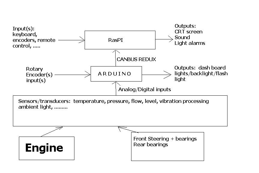
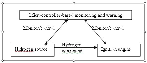
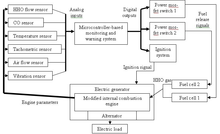
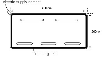
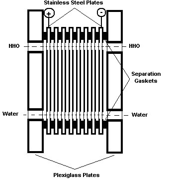

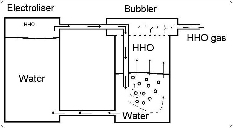
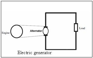
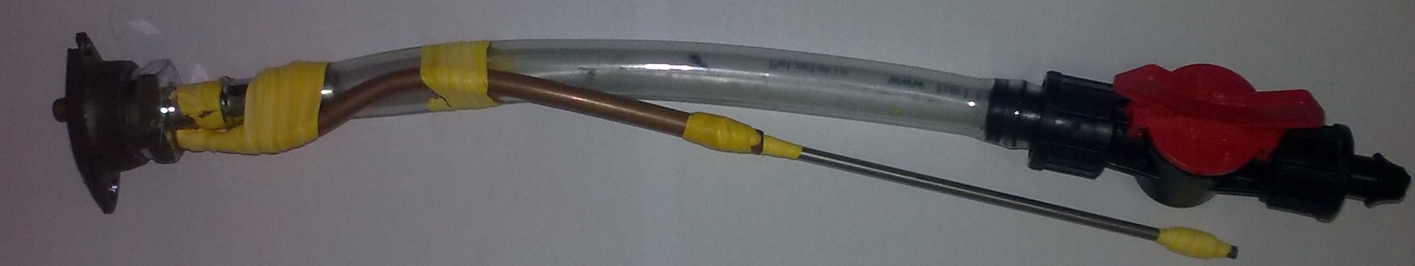
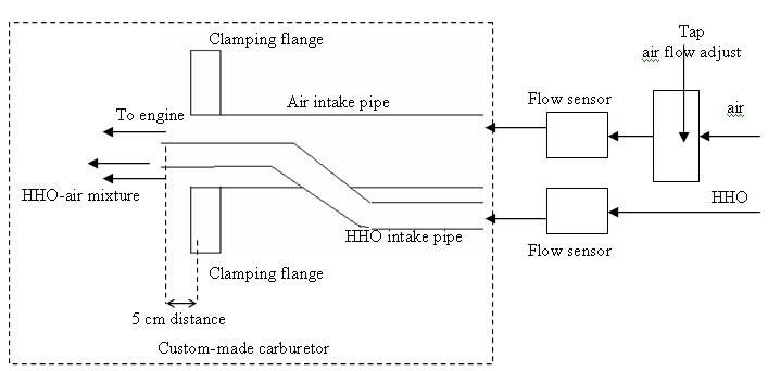
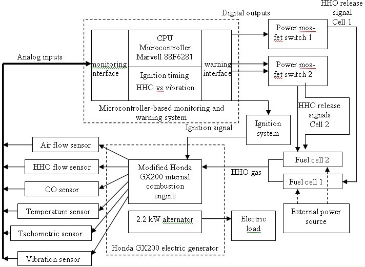
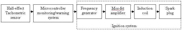
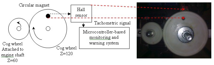
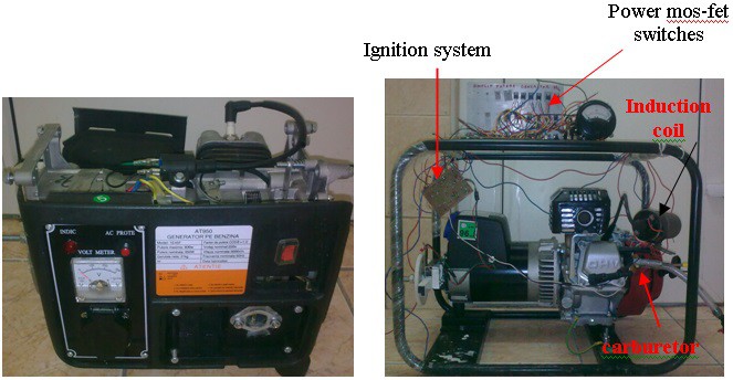
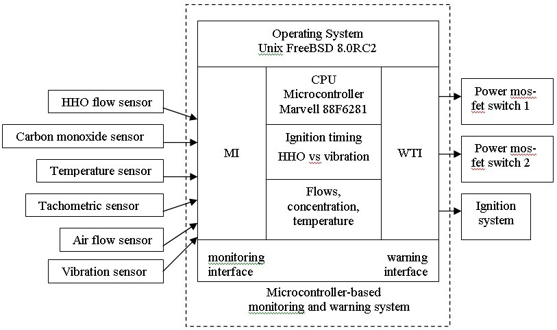
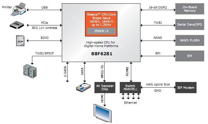
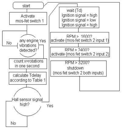
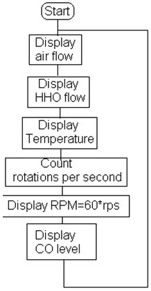
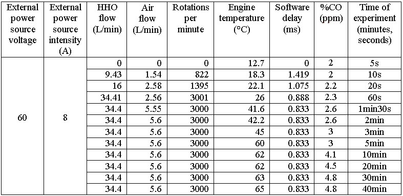
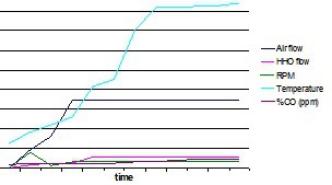
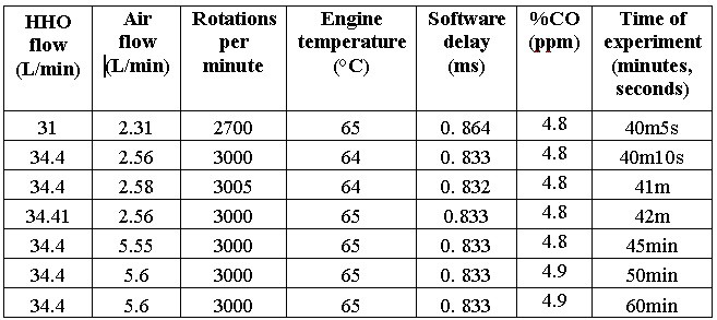


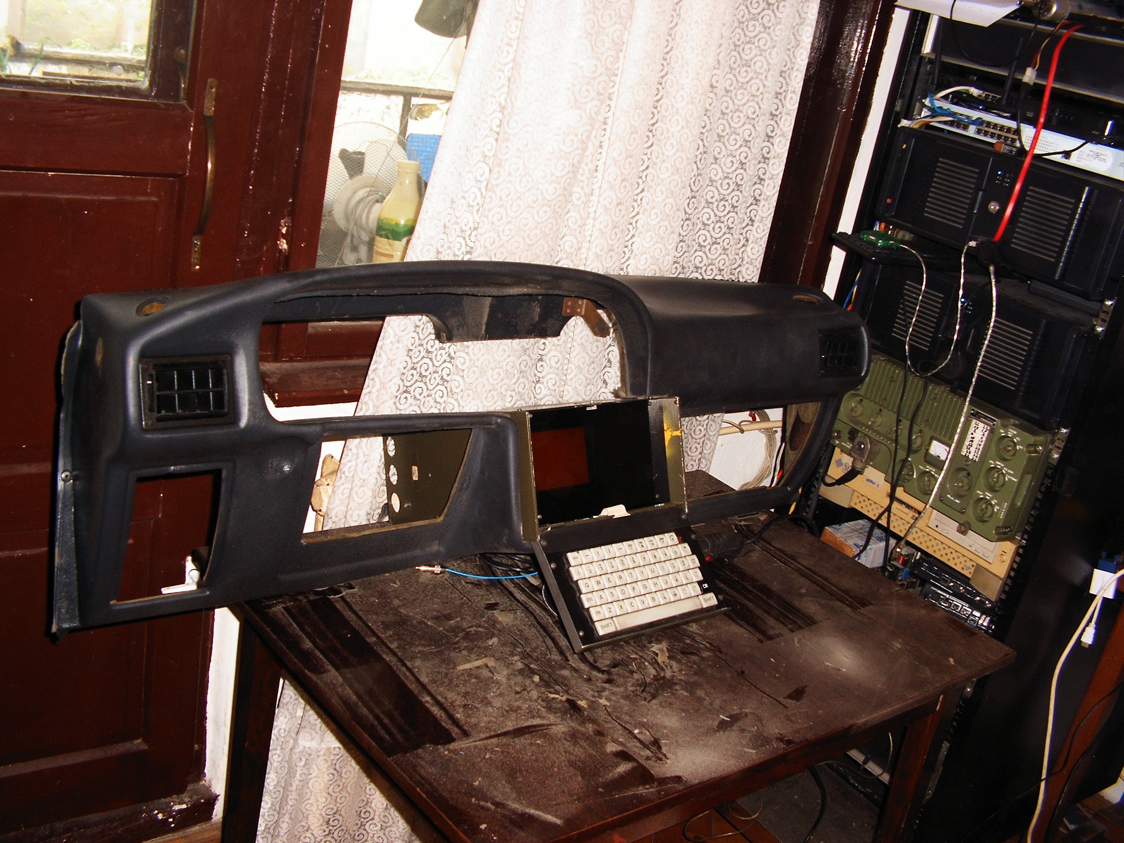
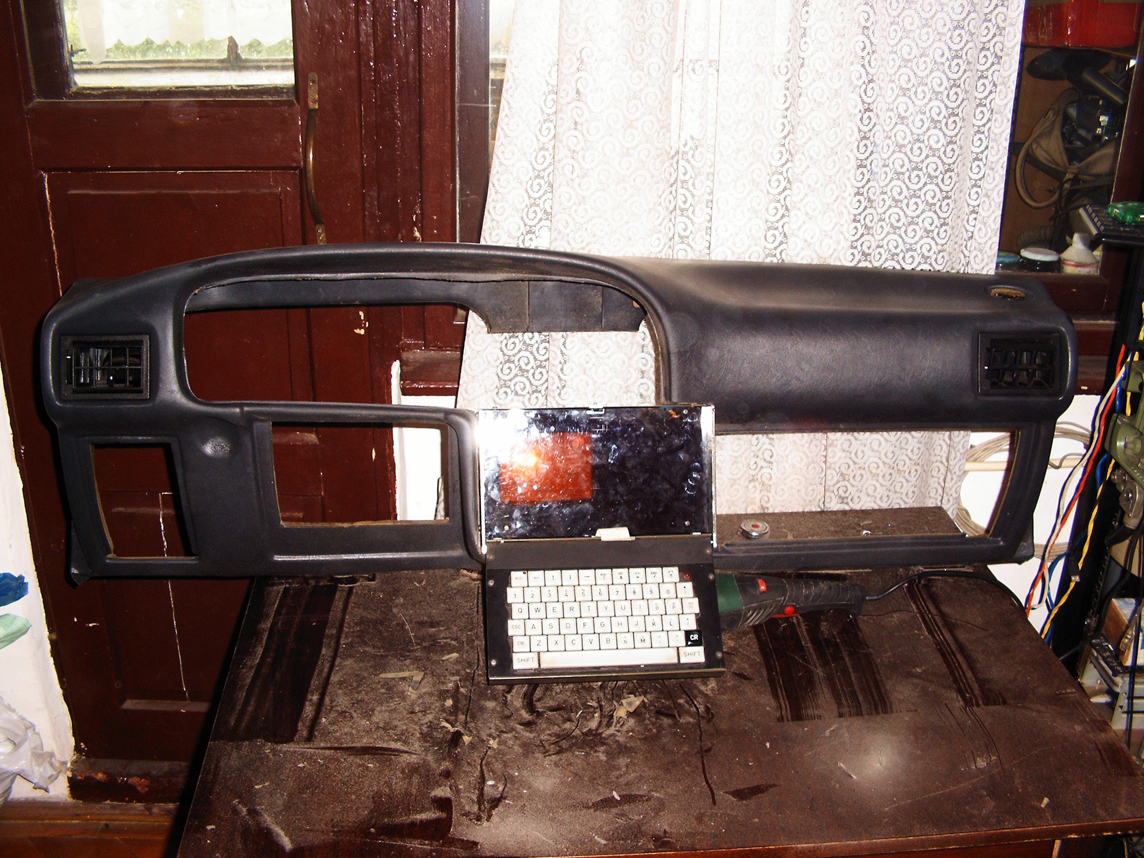
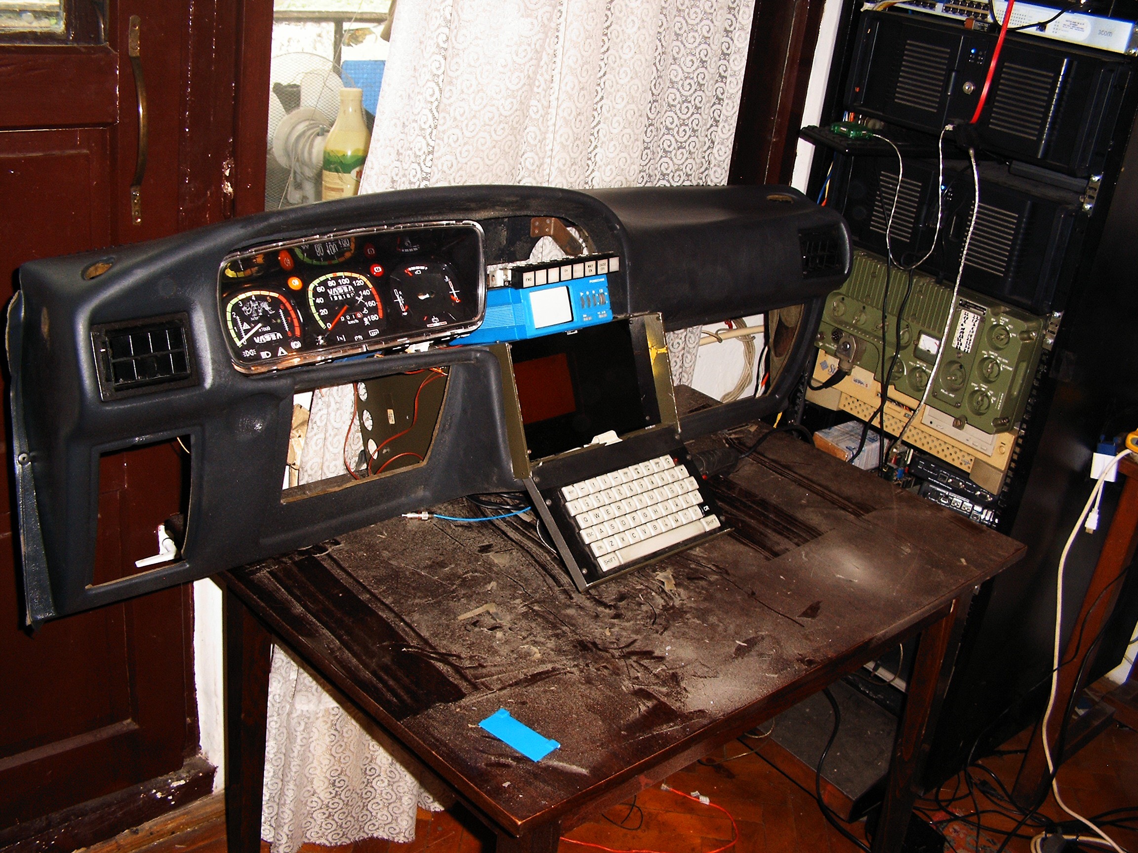
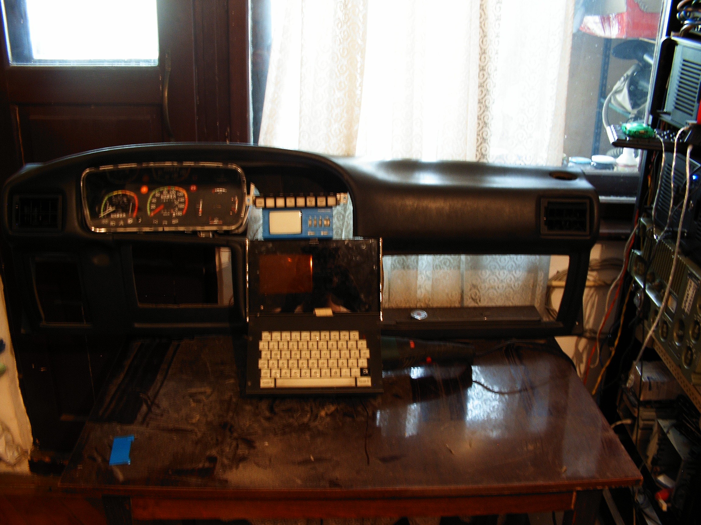
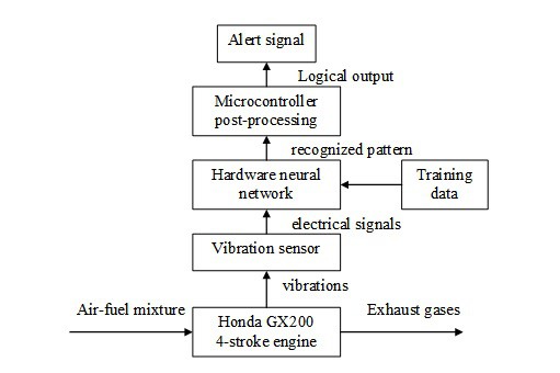
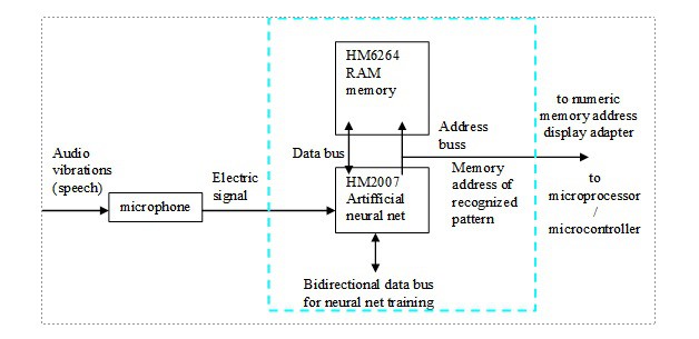
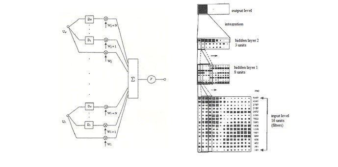
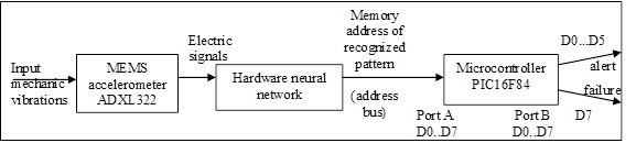

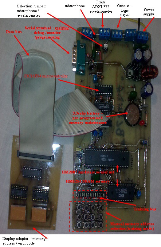
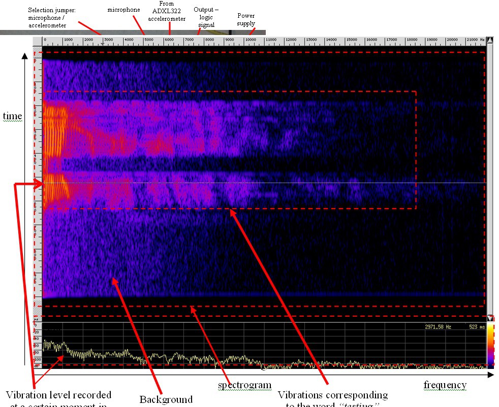
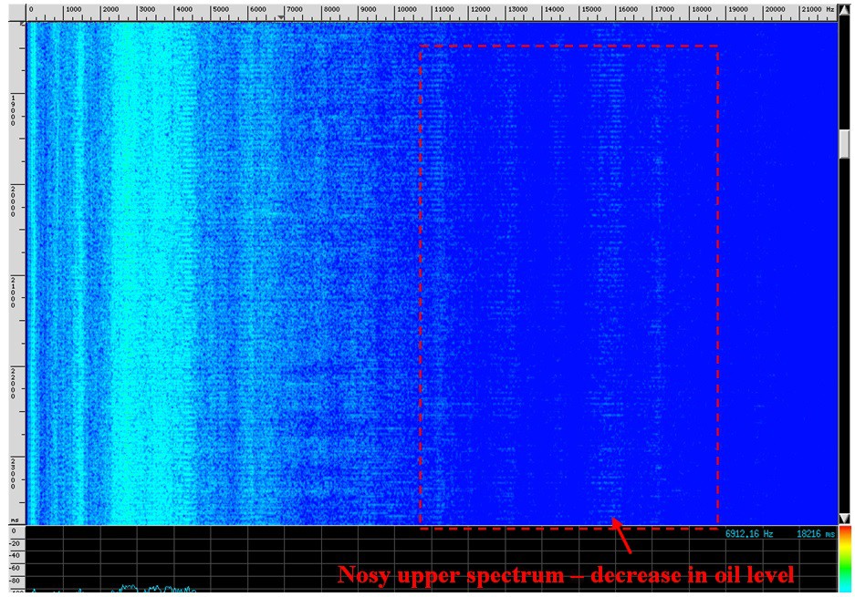
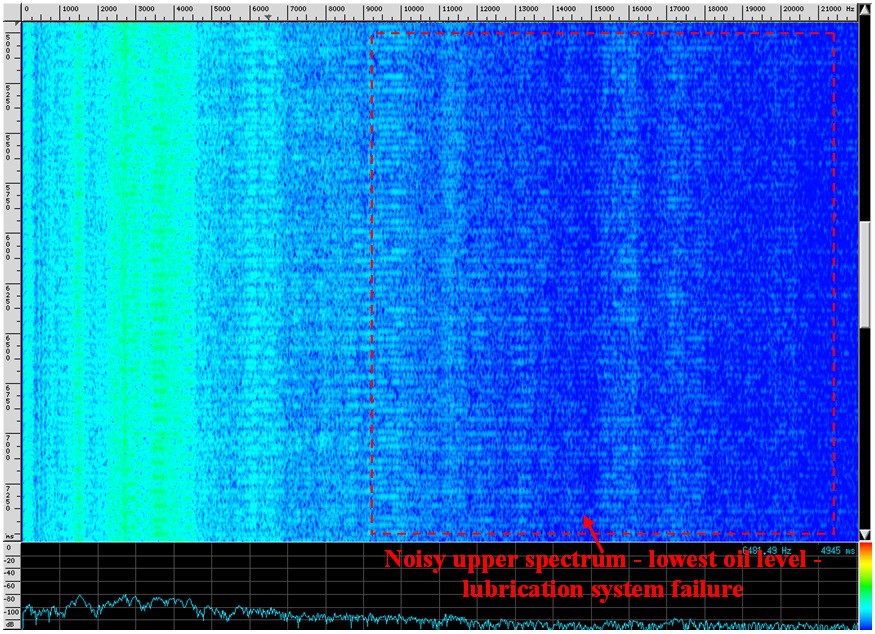
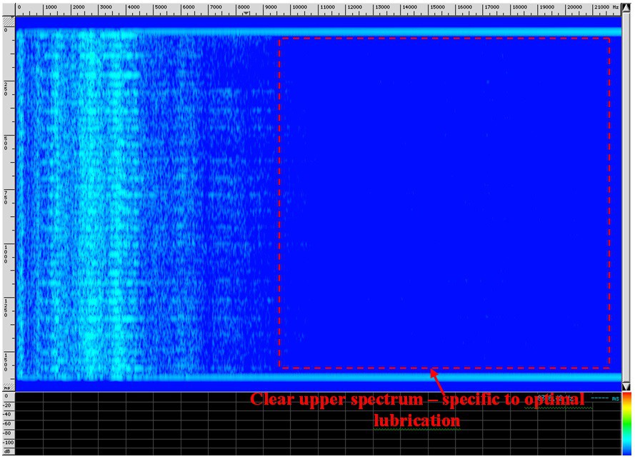

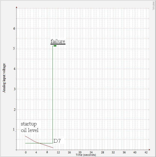


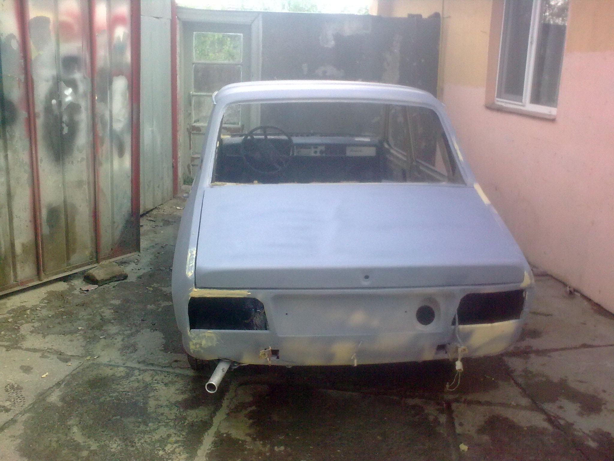
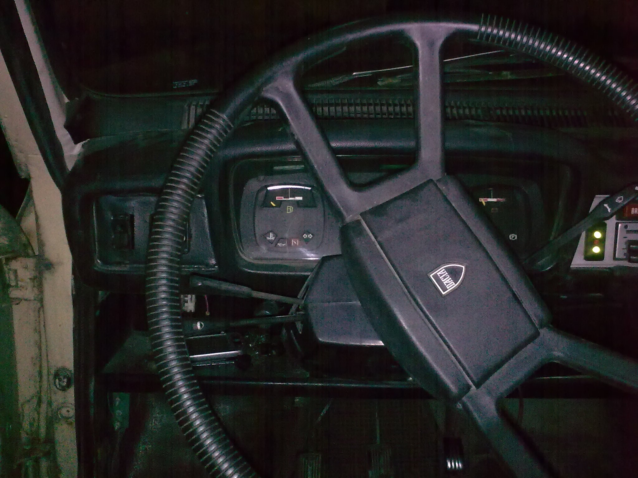
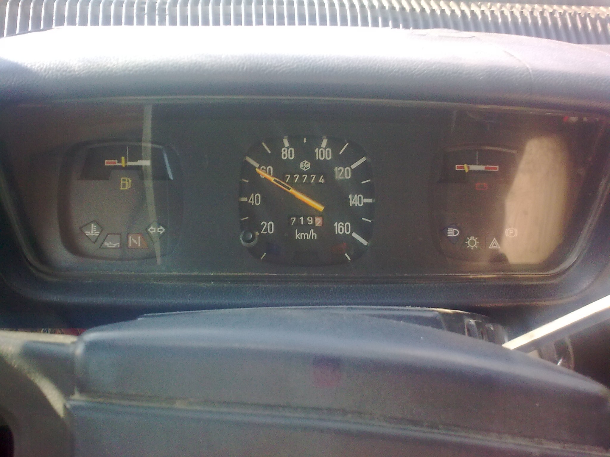

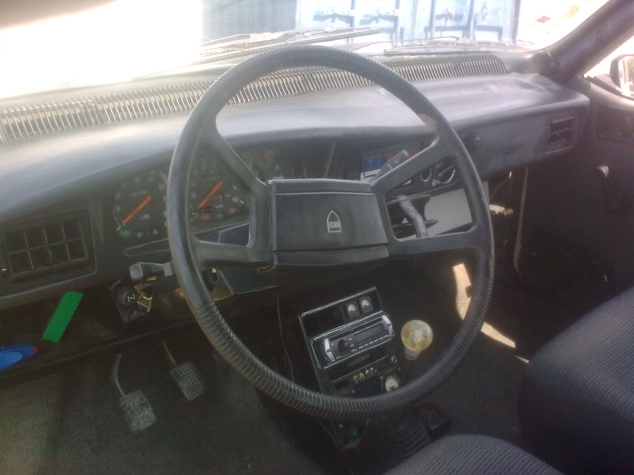
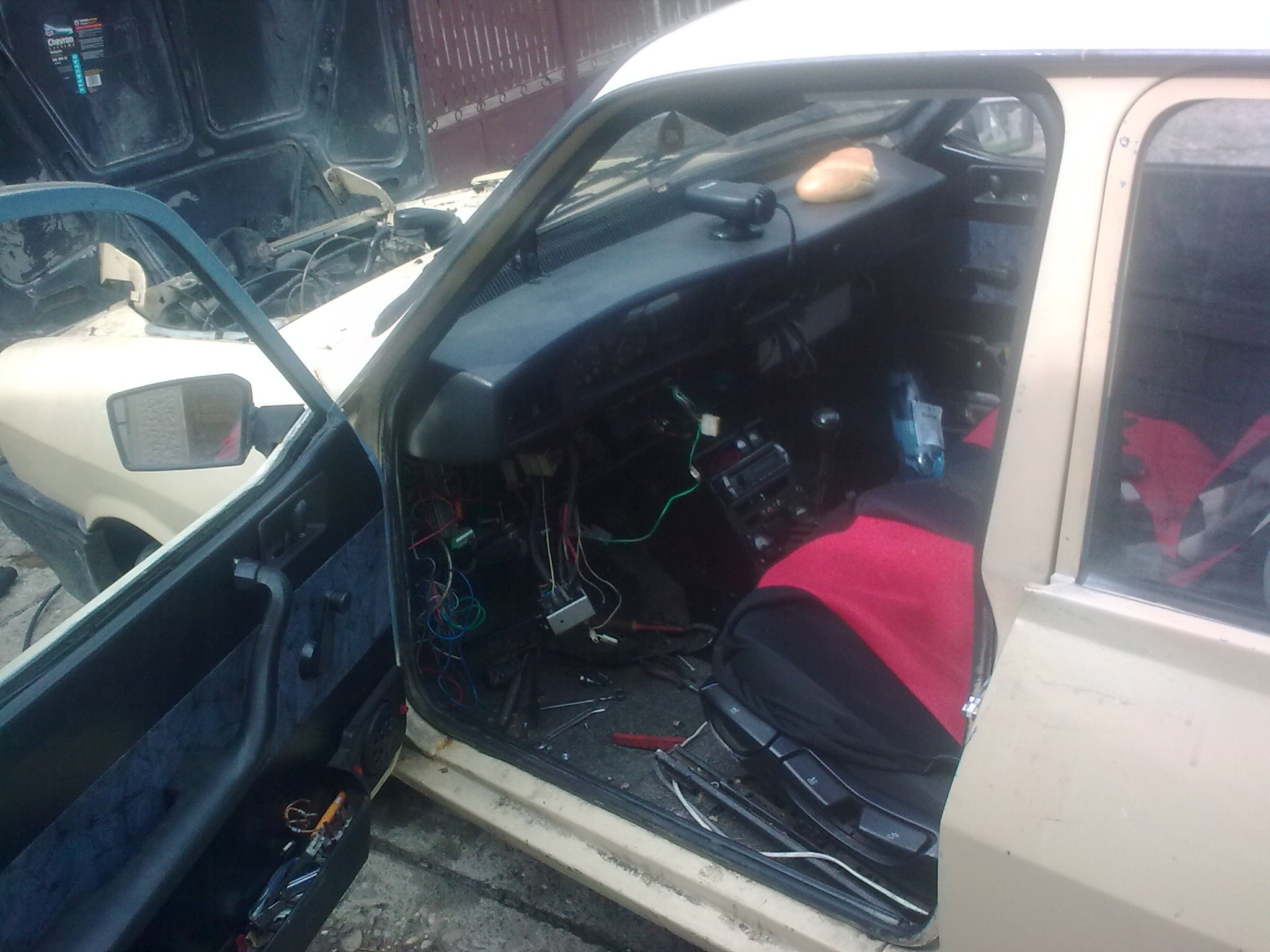


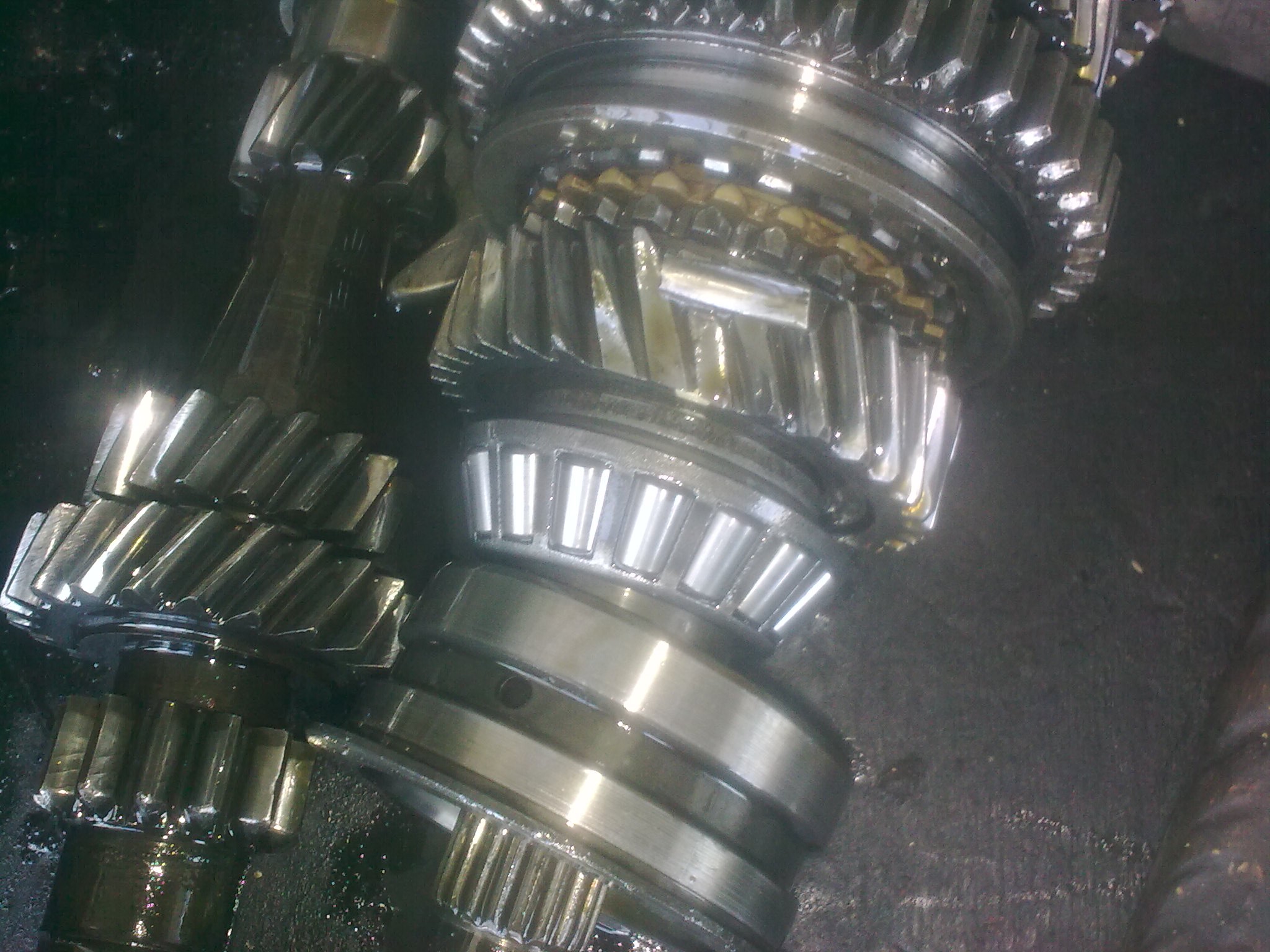
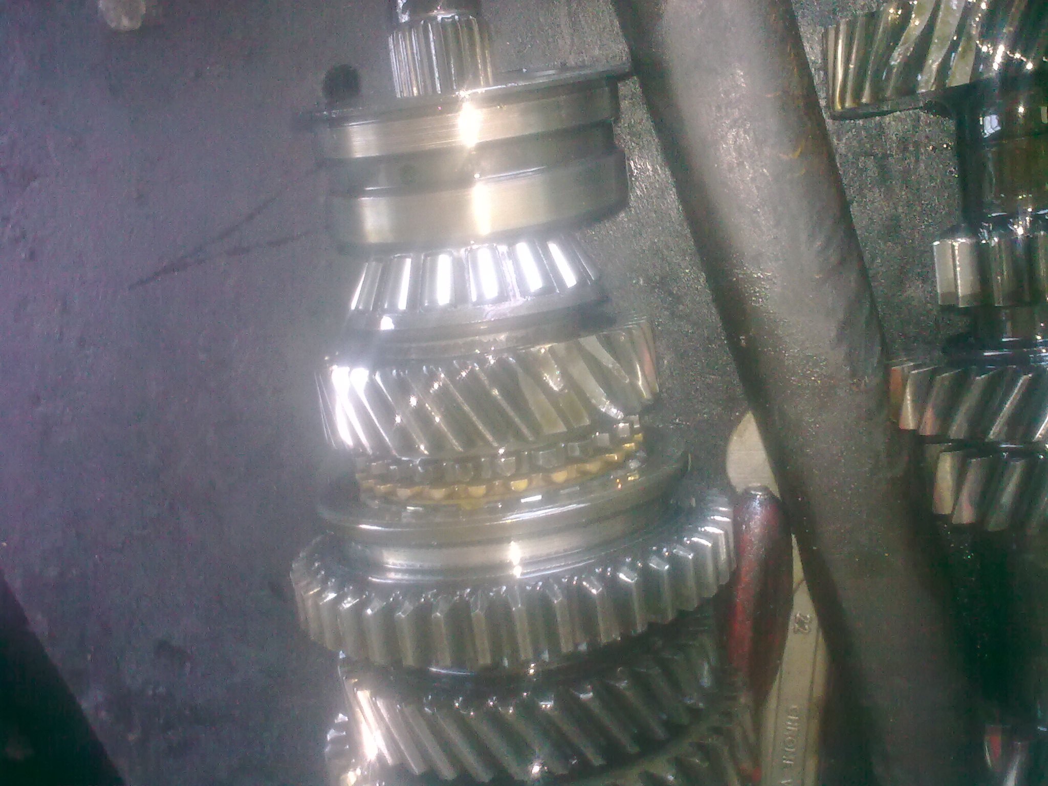
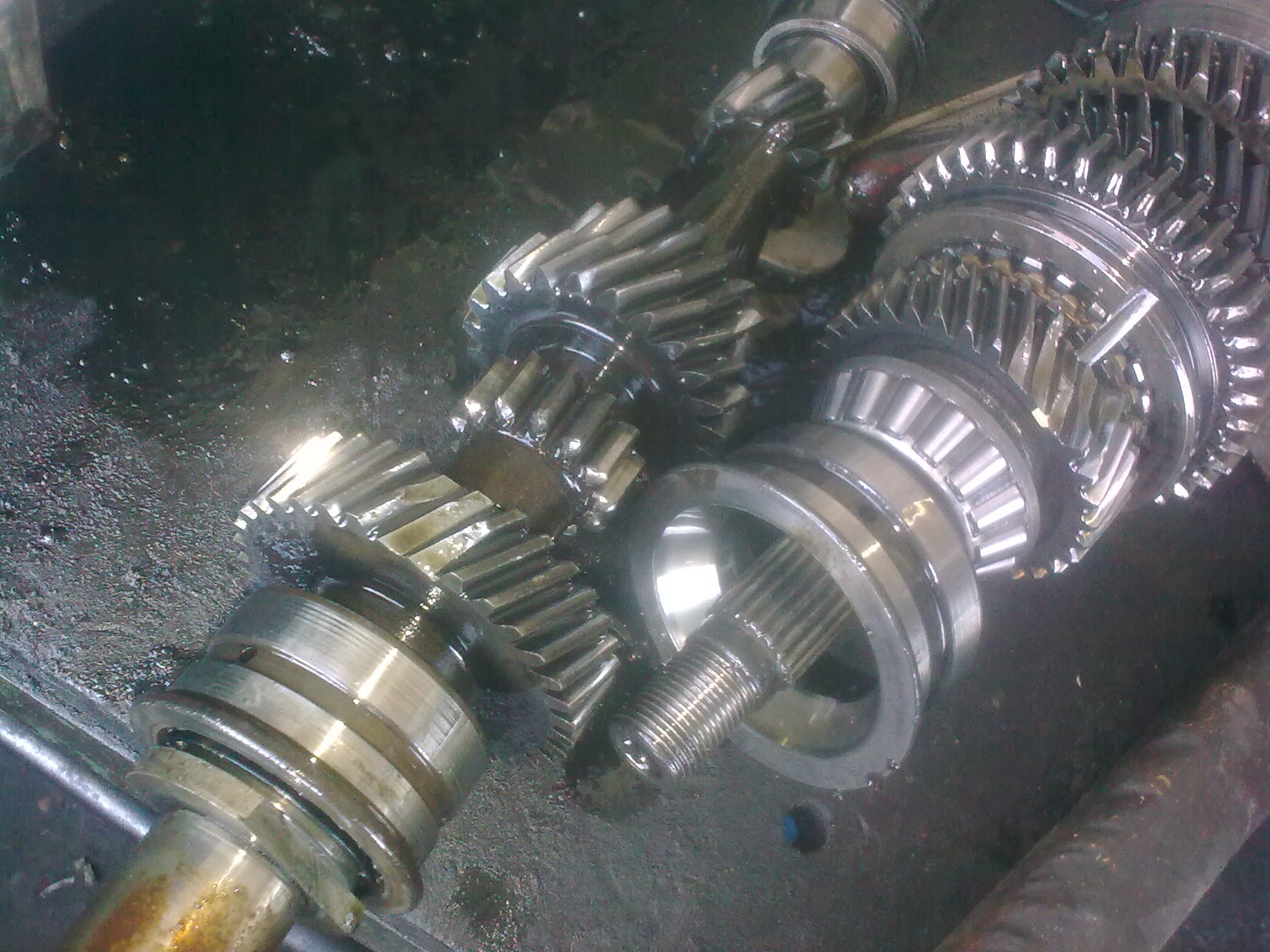
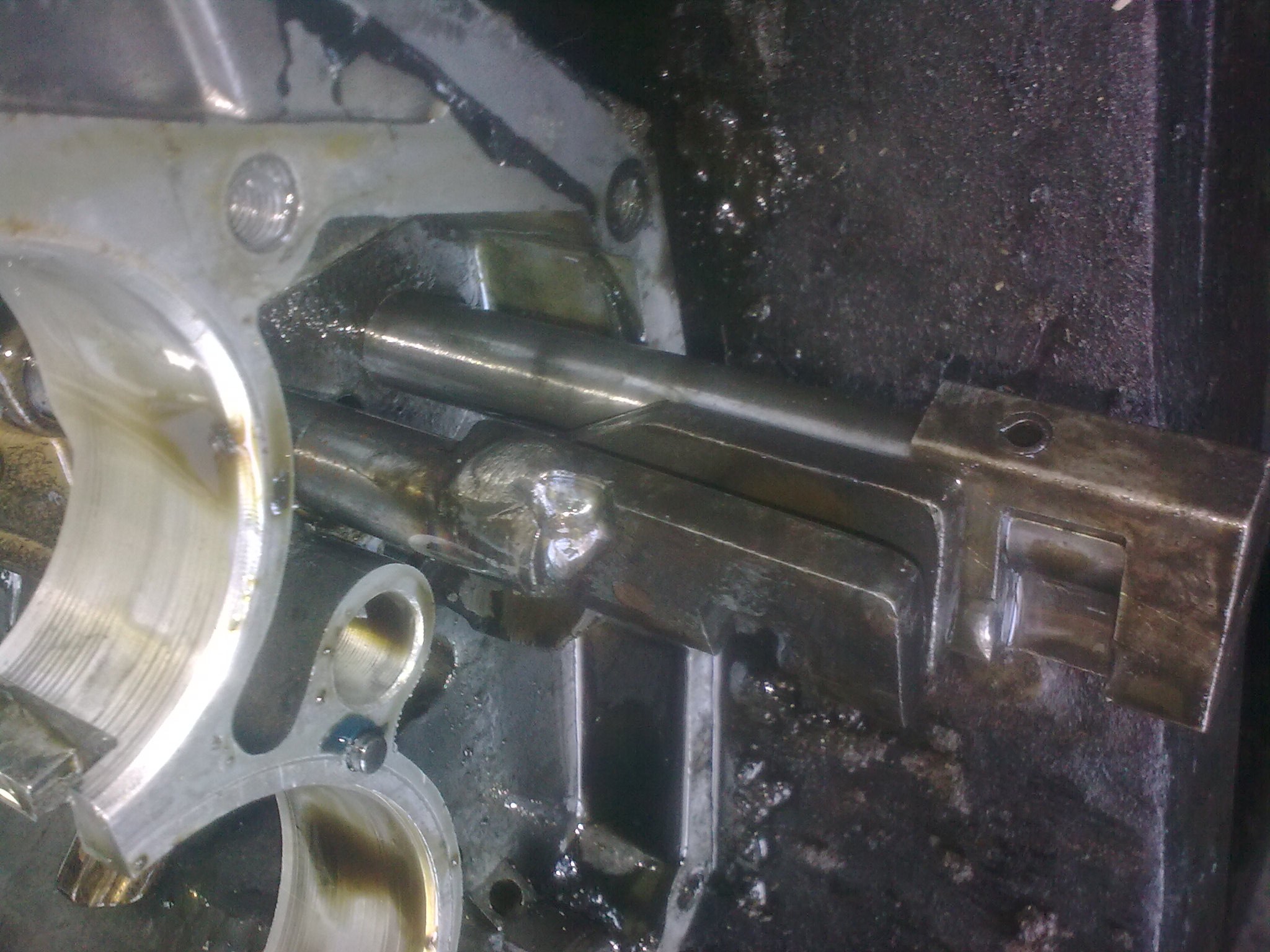
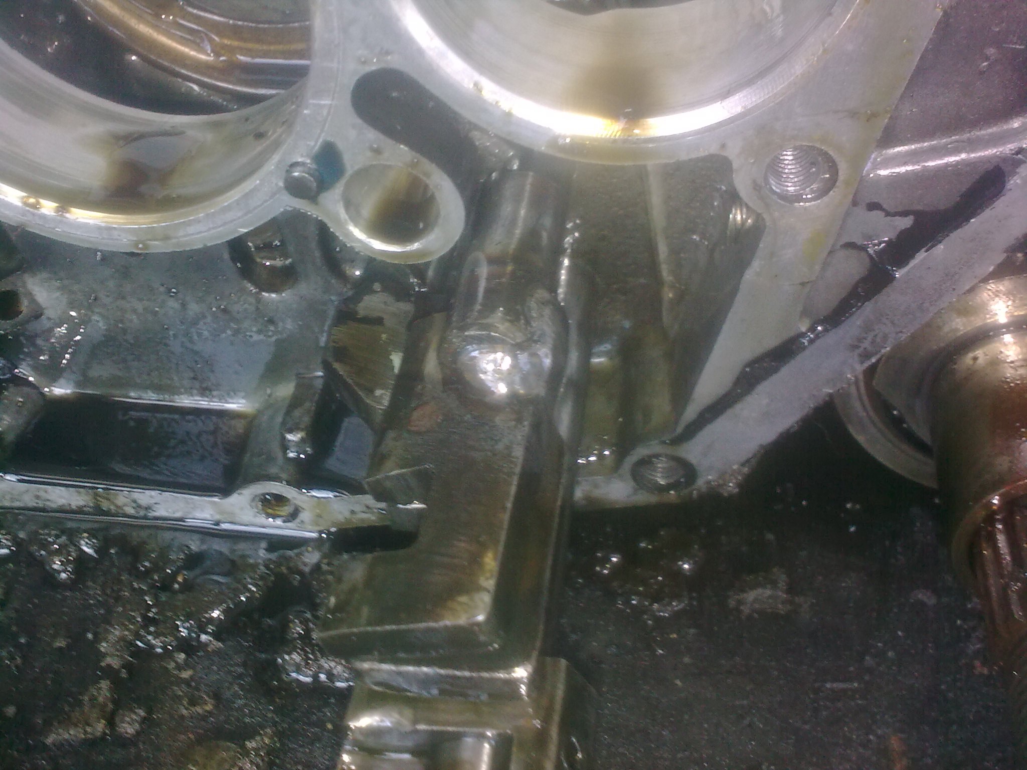
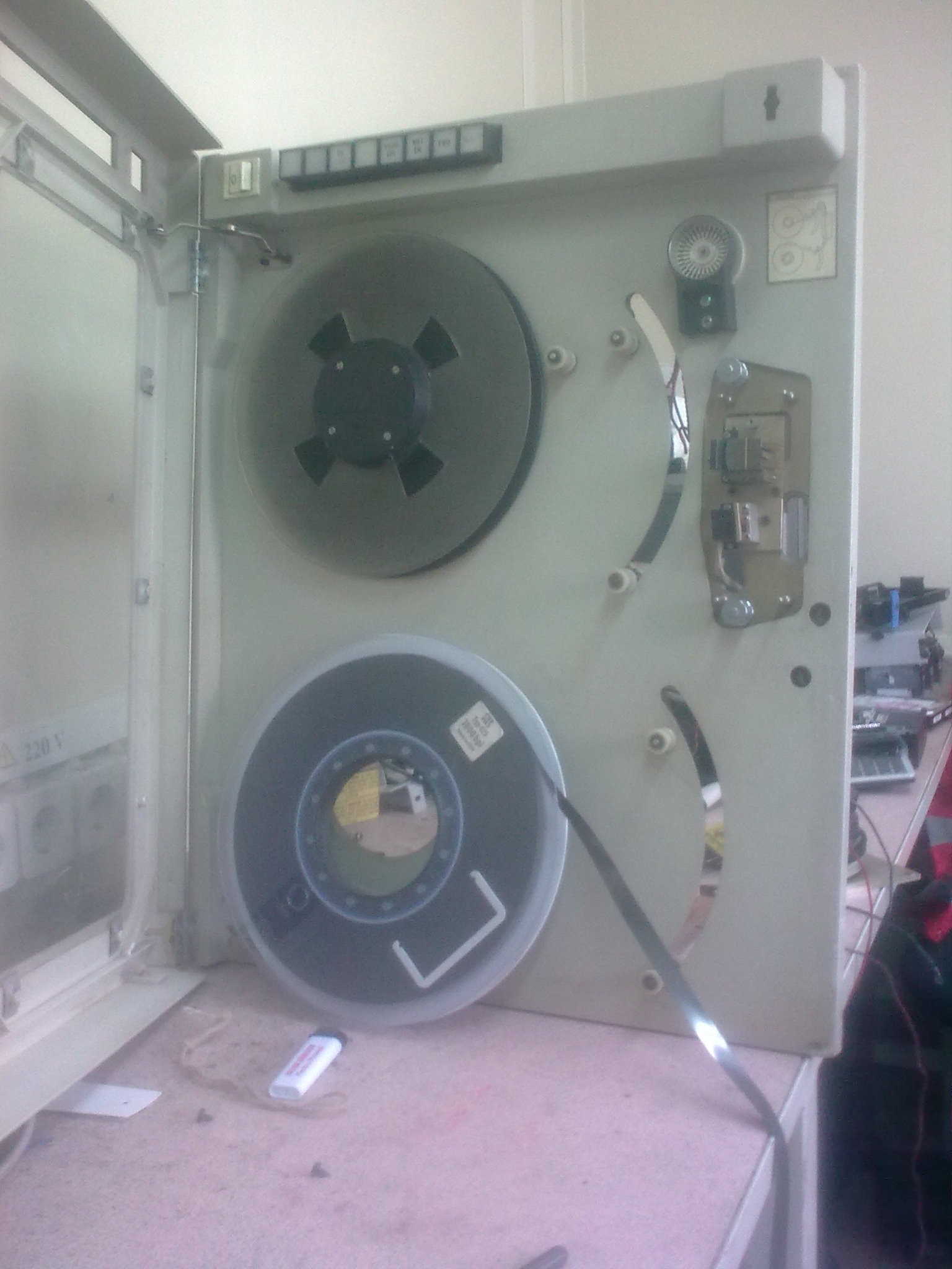
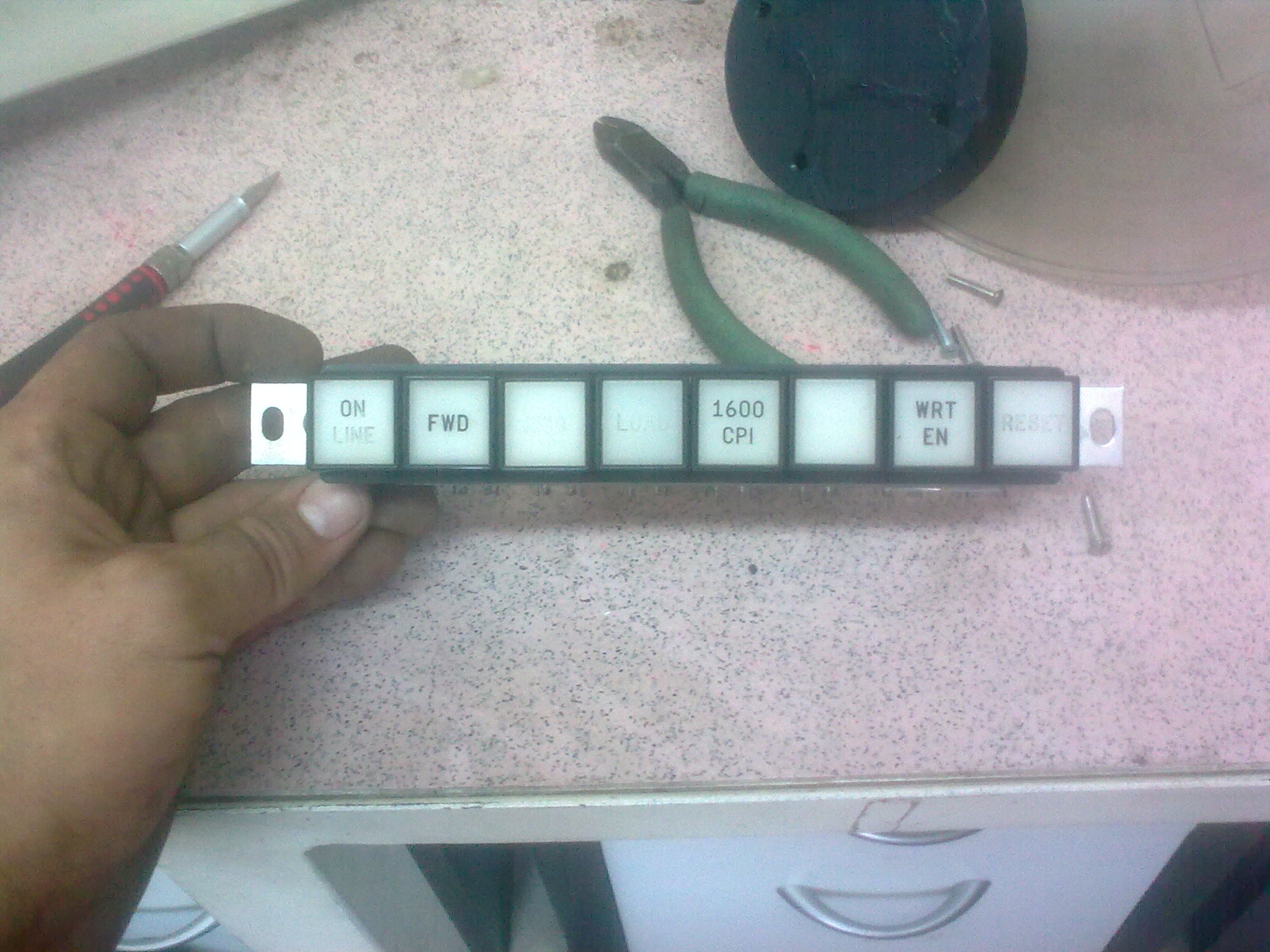
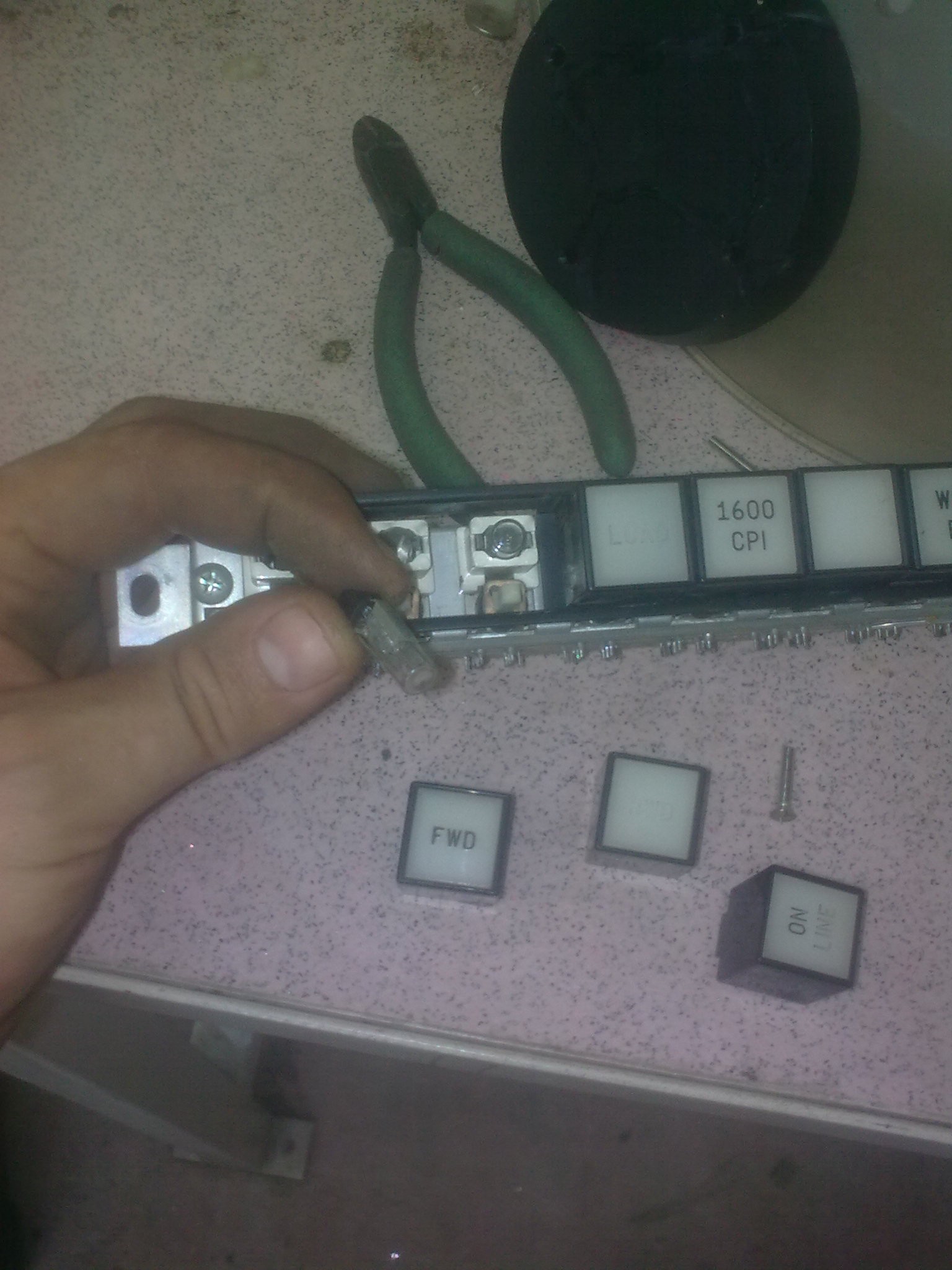
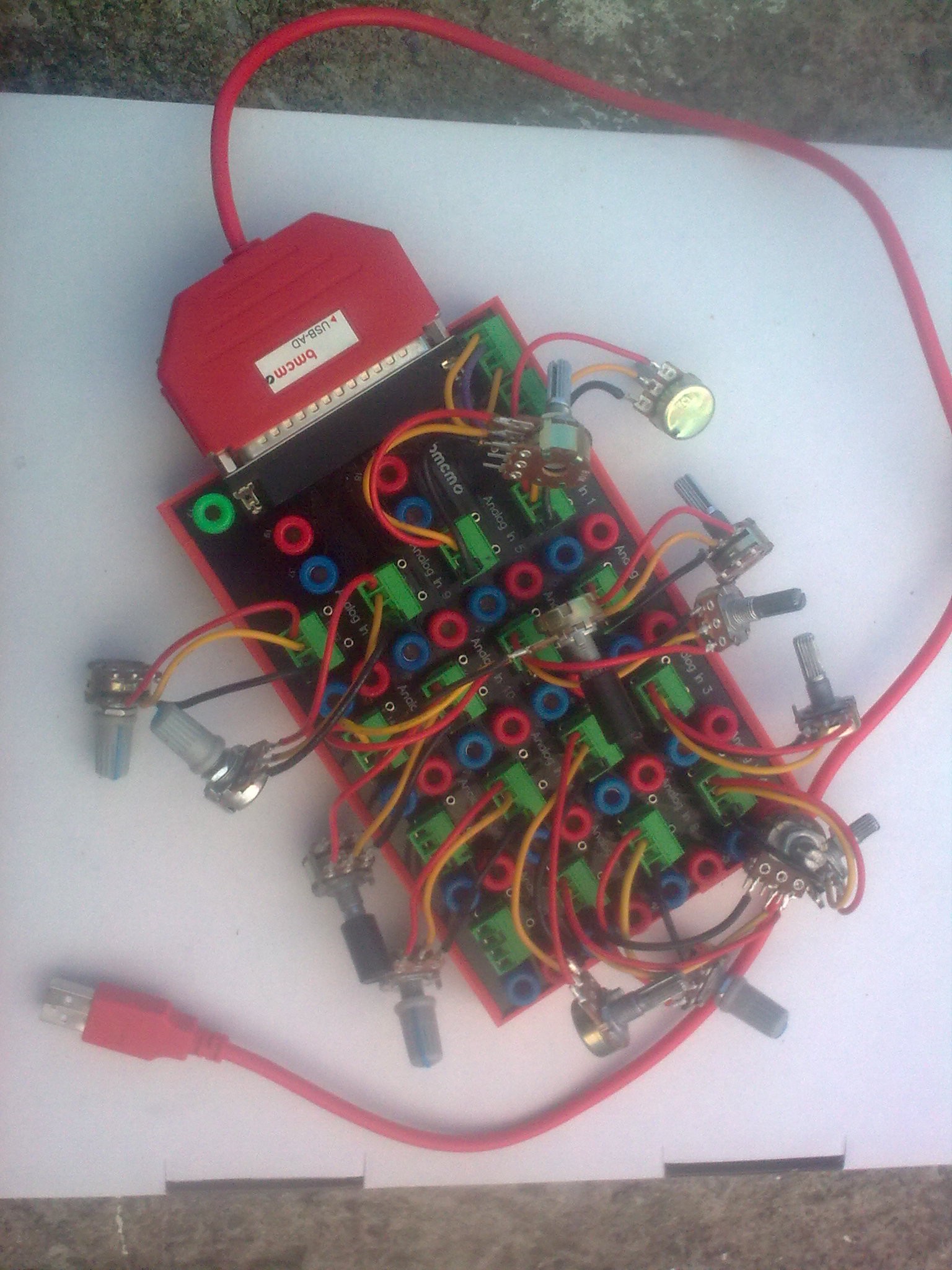


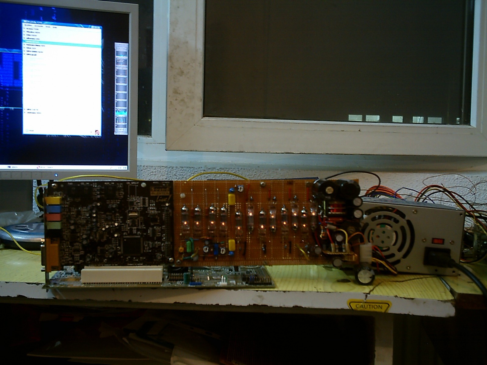
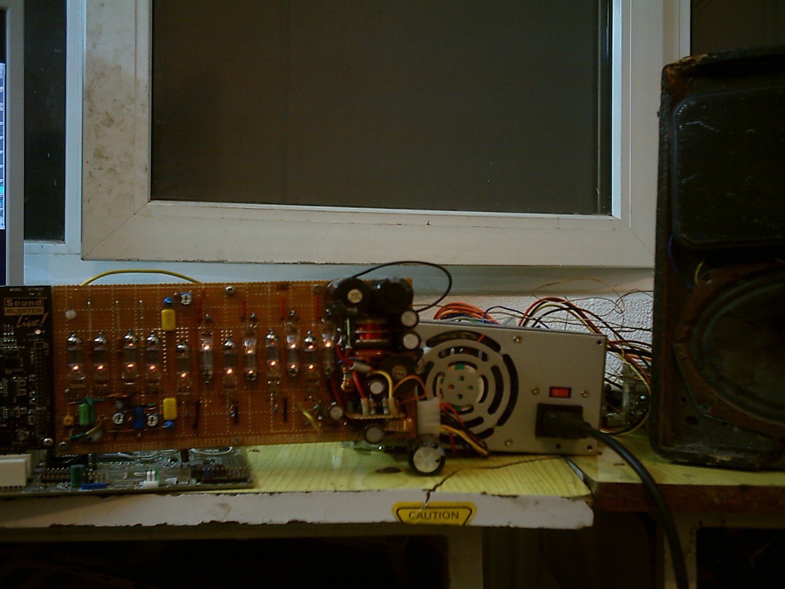
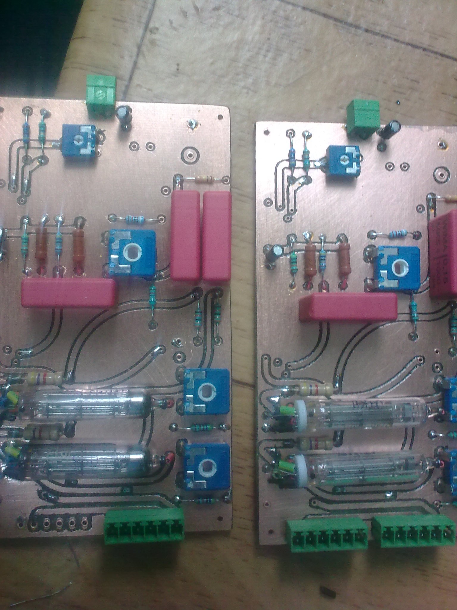
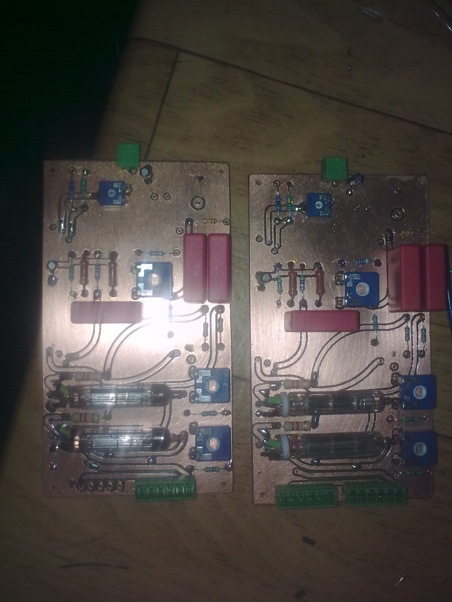
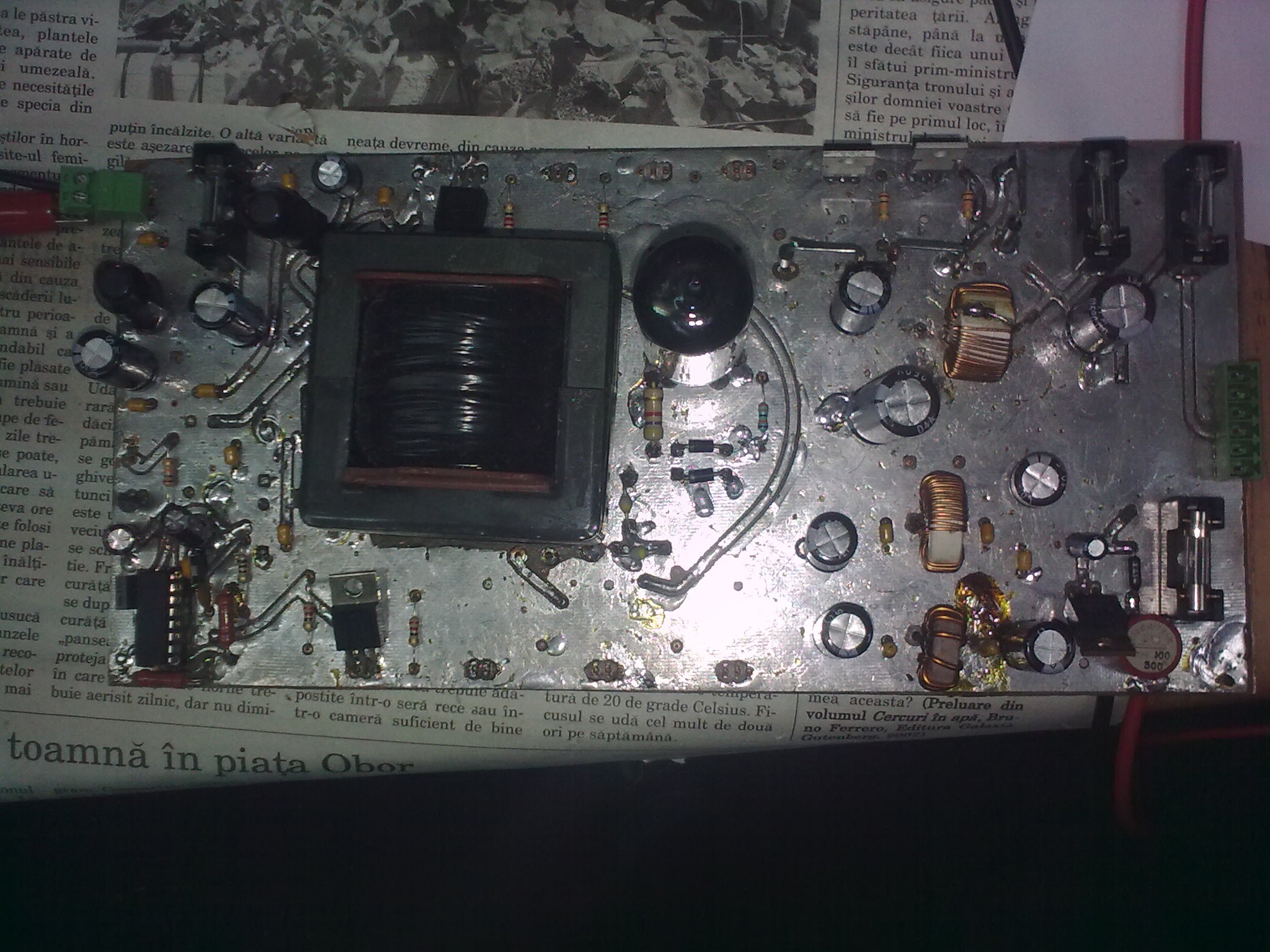
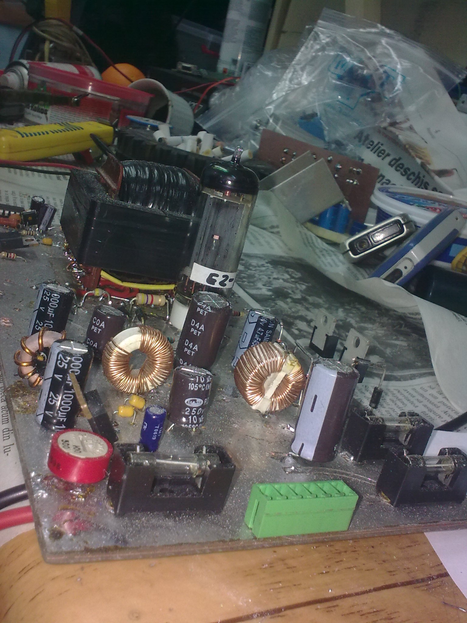
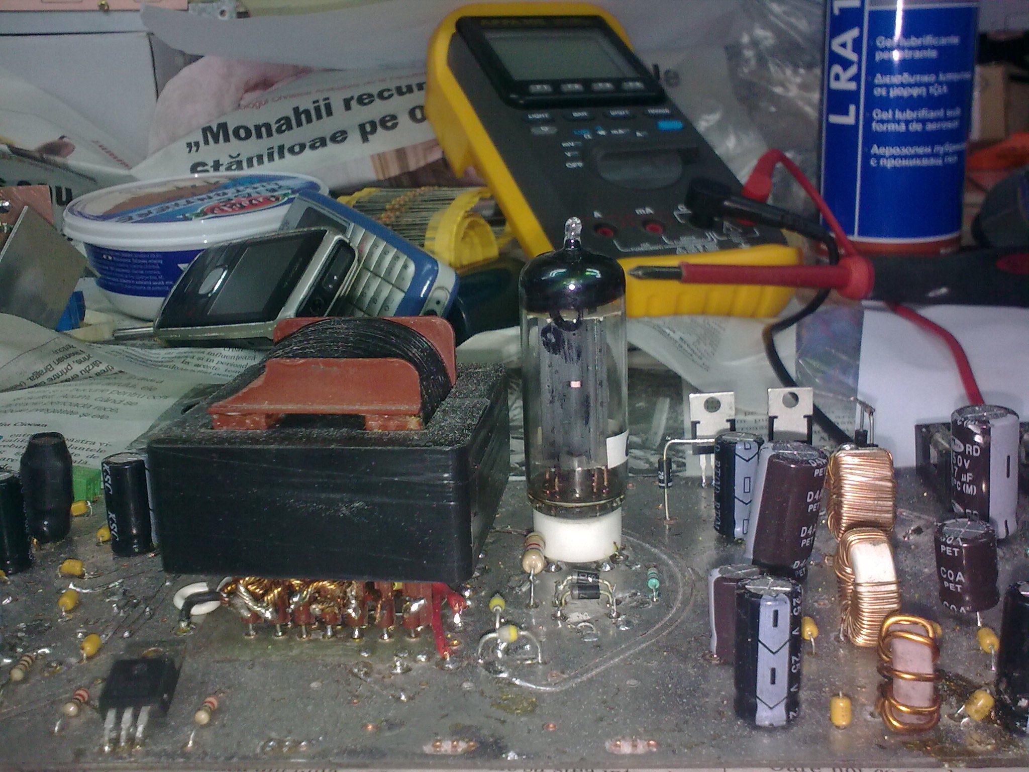
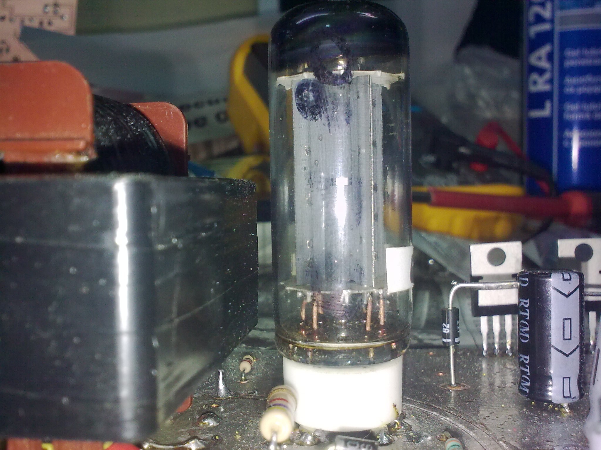
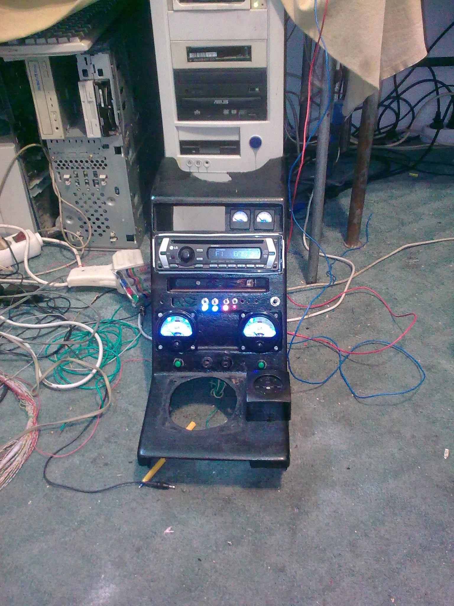
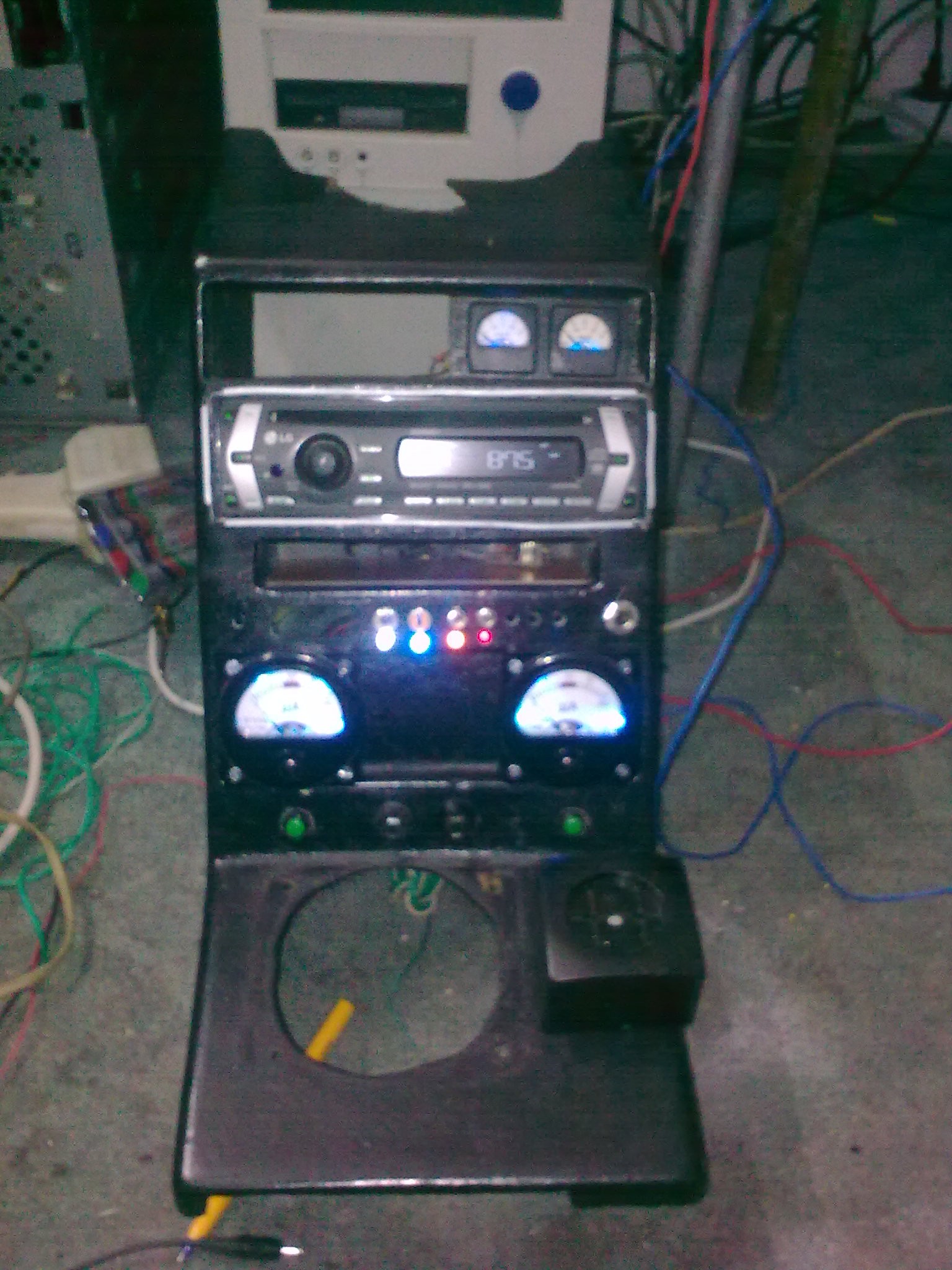
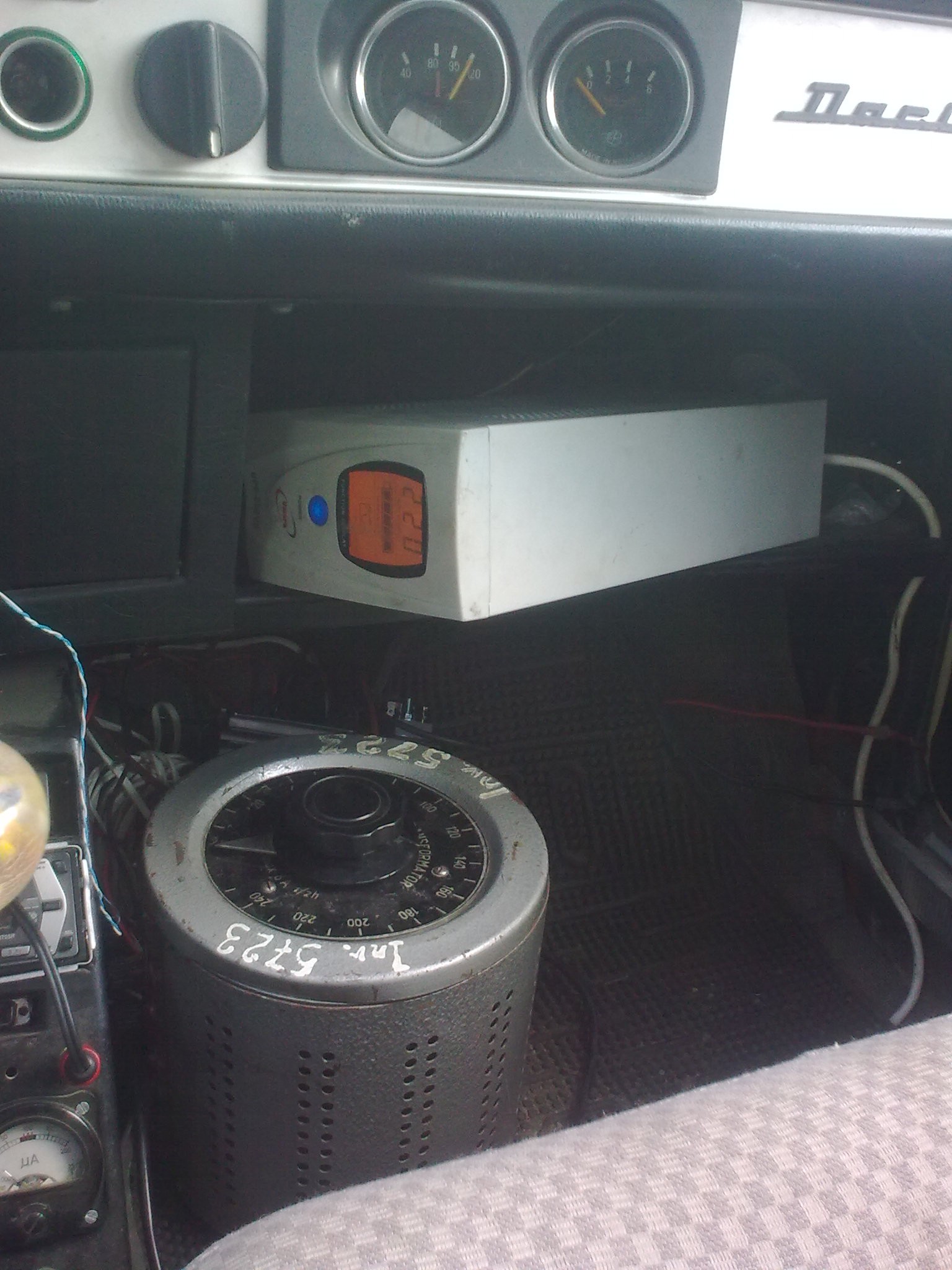

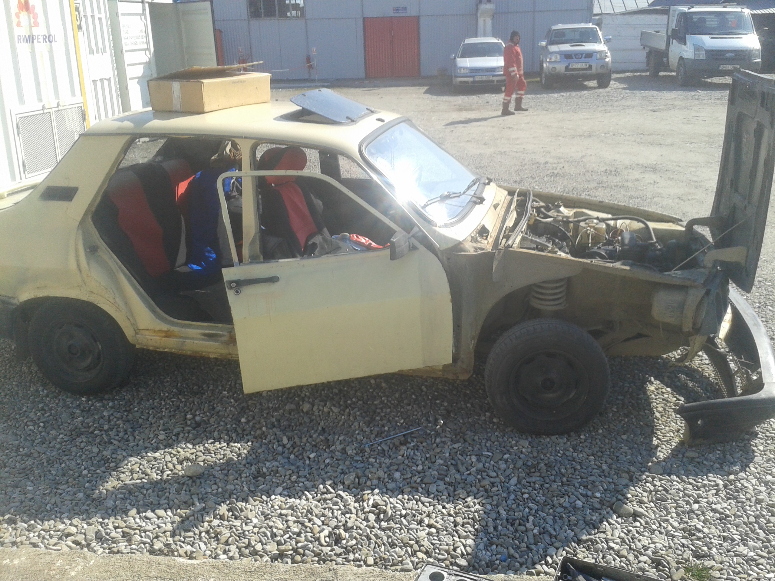


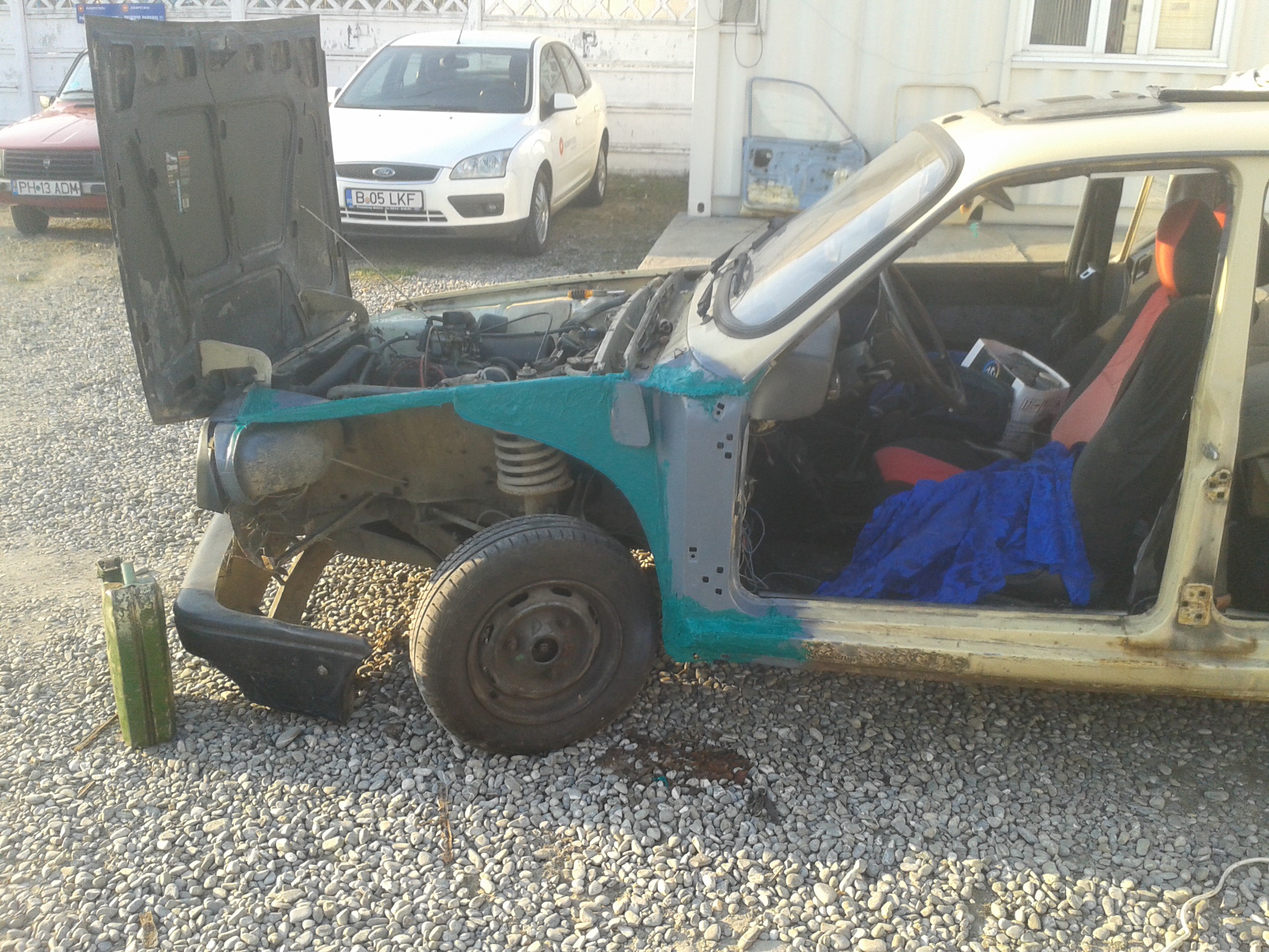

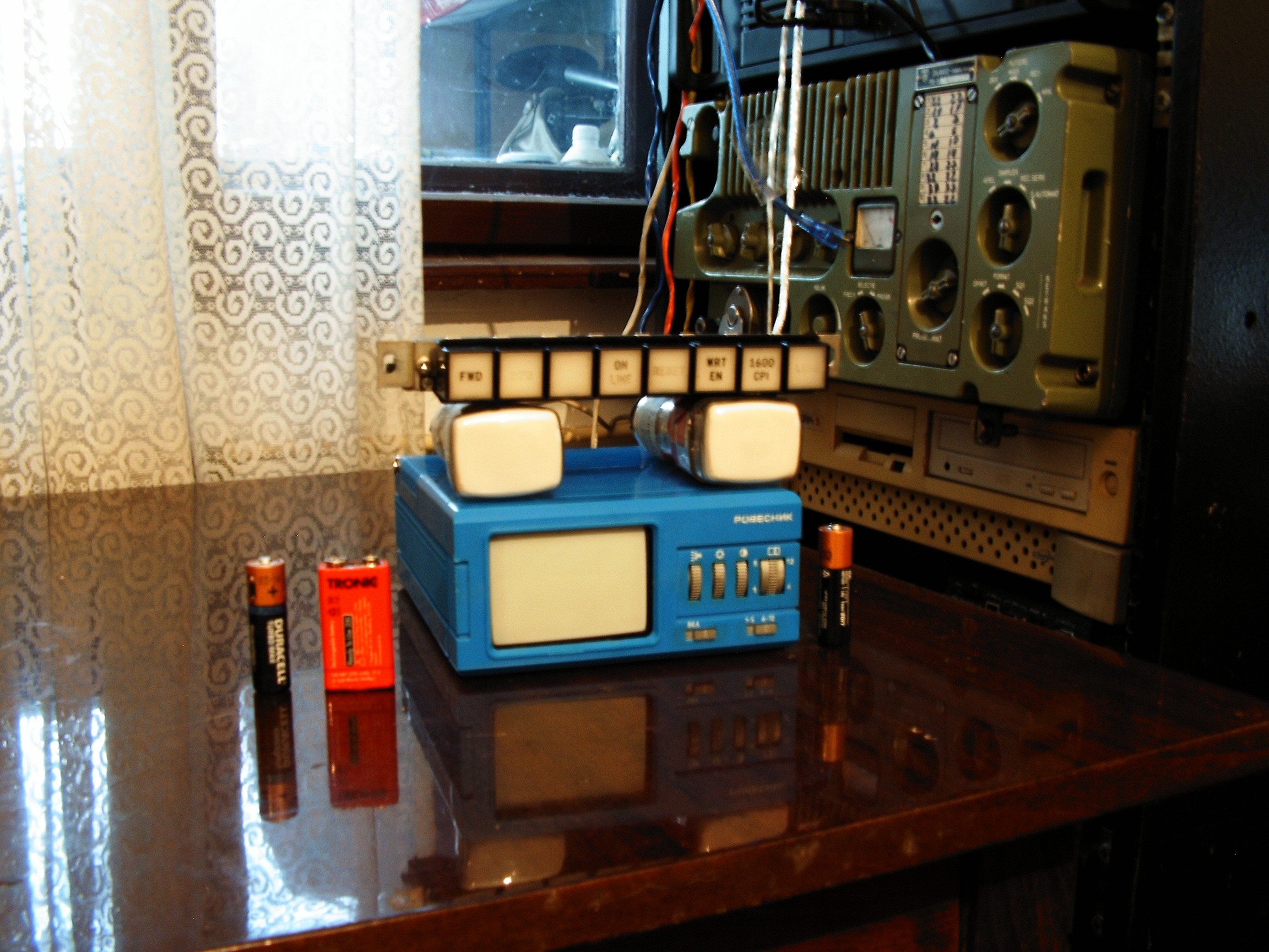
 These are the two D5-100W 2" oscilloscope CRTs which are supposed to stay in the right side of the color display. Also the "Rovesnik" Russian TV set in perfect working condition. The 8 button keypad will have new labels as soon as I define their functions.
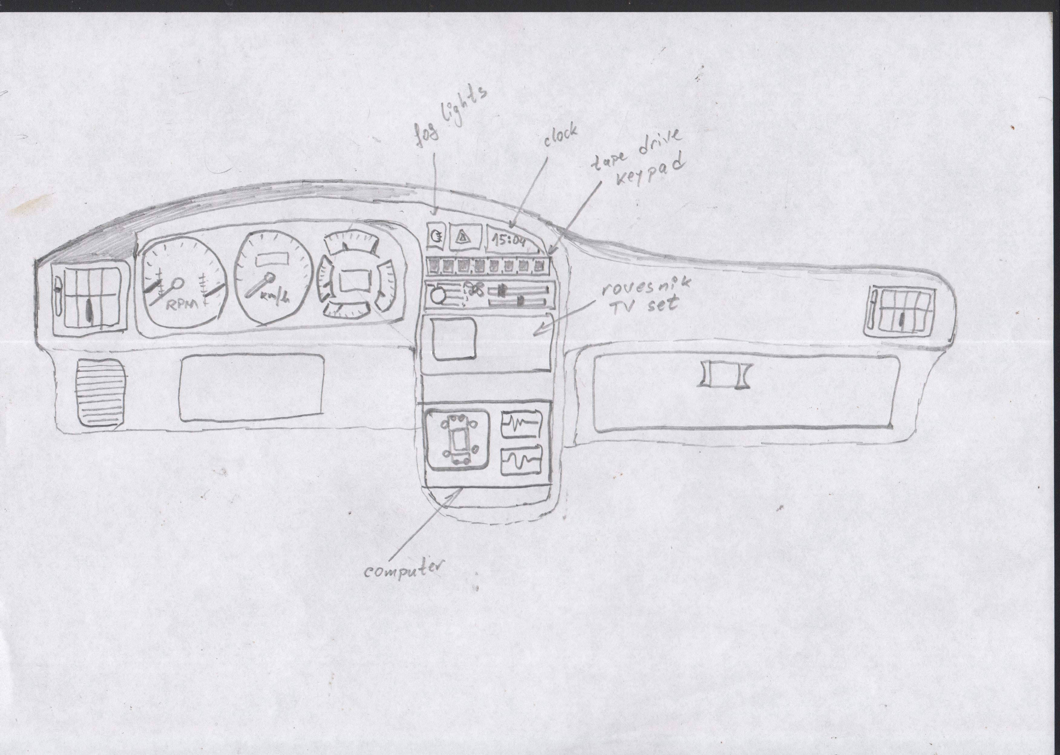 General view of the interface.
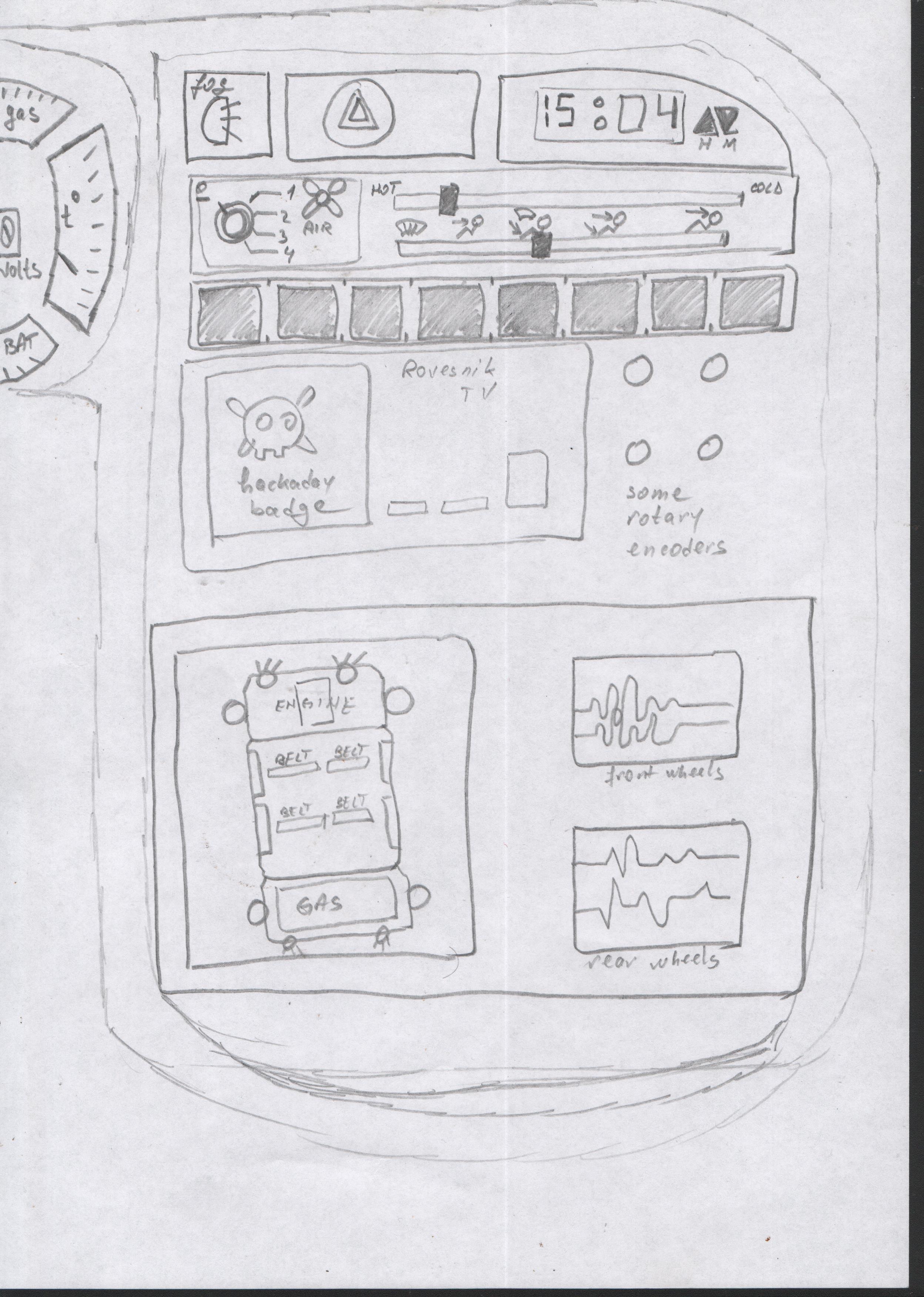 Control panel details.
 screen with automobile schematic: color CRT display. In the right side - two oscilloscope screens displaying some random graphs. Keyboard is not shown in the concept. It is possible it may interfere with the gear shifter.