 bosko
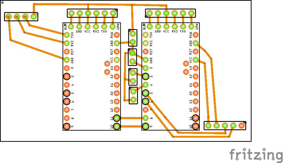
boskoHere is the first dashboard PCB prototype. In this PCB the sockets were soldered for GPS, Wireless, Buttons, FTDI and Arduinos. The Arduino on the left side is connected with the GPS and that arduino is calculating only the GPS and that information is sent to the other Arduino. The Arduino on the right is connected with Wireless module and buttons. Why I'm using two Arduinos? It's because reading the GPS signal needs about 2 seconds to get good or valid data and because I'm controlling the wireless motor I don't want to have delay that's about 2000ms between each signals. Big delay between motor and dashboard isn't safe and isn't smooth. In this prototype I was using button to increase and decrease throttle of the motor.
Discussions
Become a Hackaday.io Member
Create an account to leave a comment. Already have an account? Log In.