-
Part 10: The Re-Awakening
12/08/2019 at 13:00 • 0 commentsA few years have passed with this thing twinkling its little heart out - pining for the interactivity I'd tinkered with, but never achieved. The microcontroller world has moved along, and since this thing had no real purpose anyway, I figure it's time to simplicate!
Yes, I know that's not a word. It seems accurate, though: I'm going to complicate the display by simplifying its electronics. But what else does one do with a purposeless display, when one has ESP-01 modules sitting around doing not much of anything?
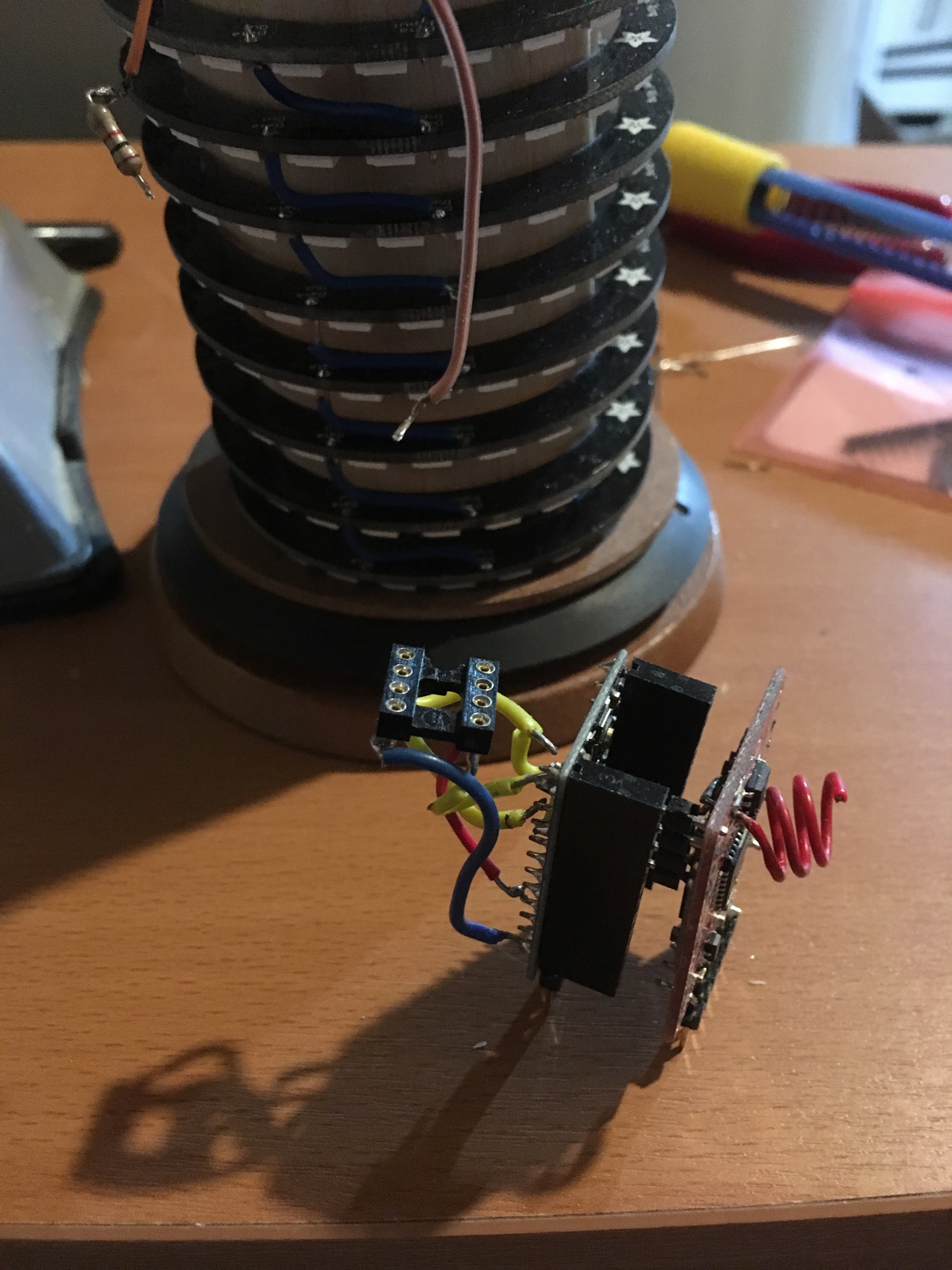
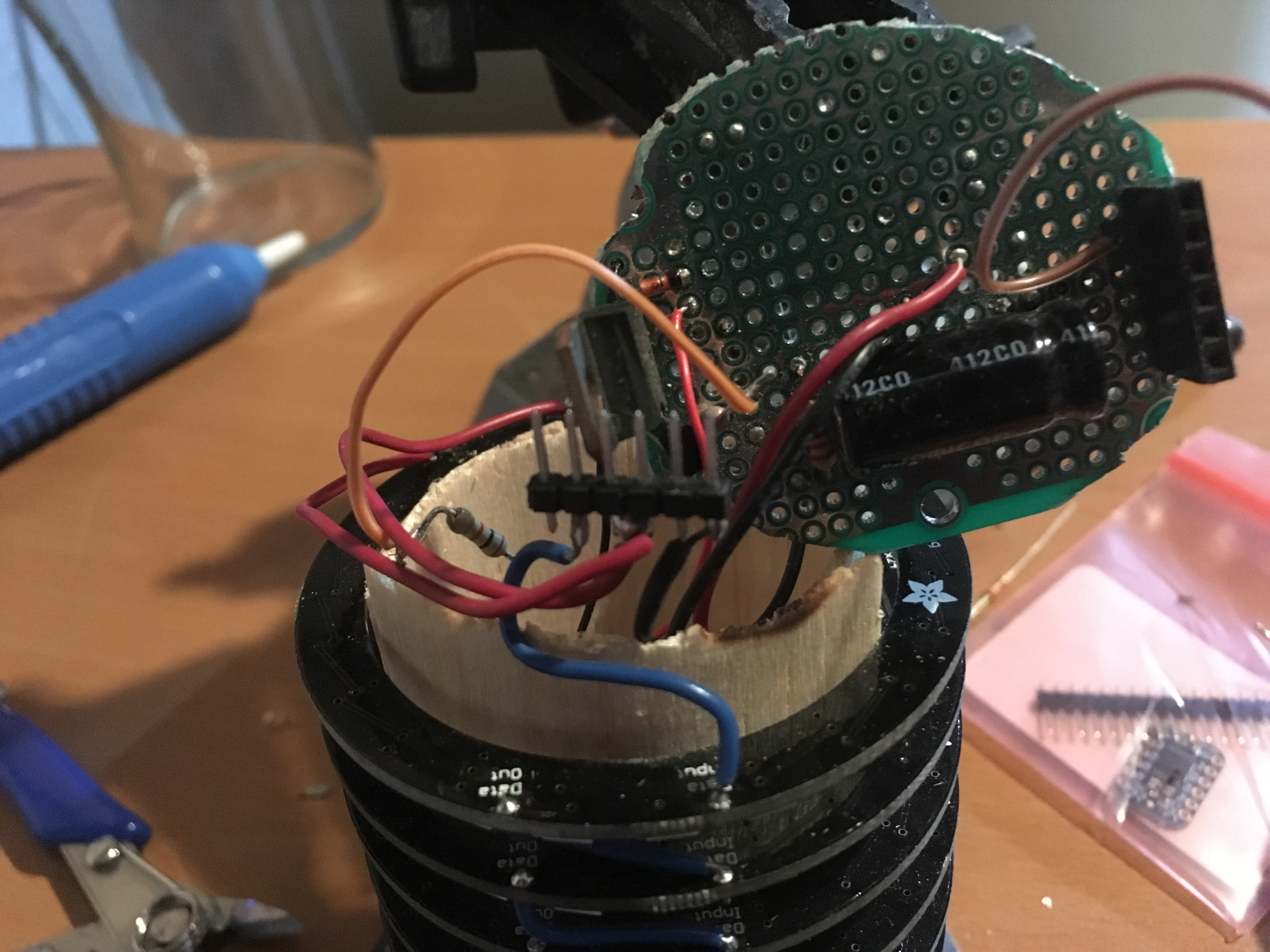
Step 1: rip out the dual-controller Moteino + Arduino Pro Mini.
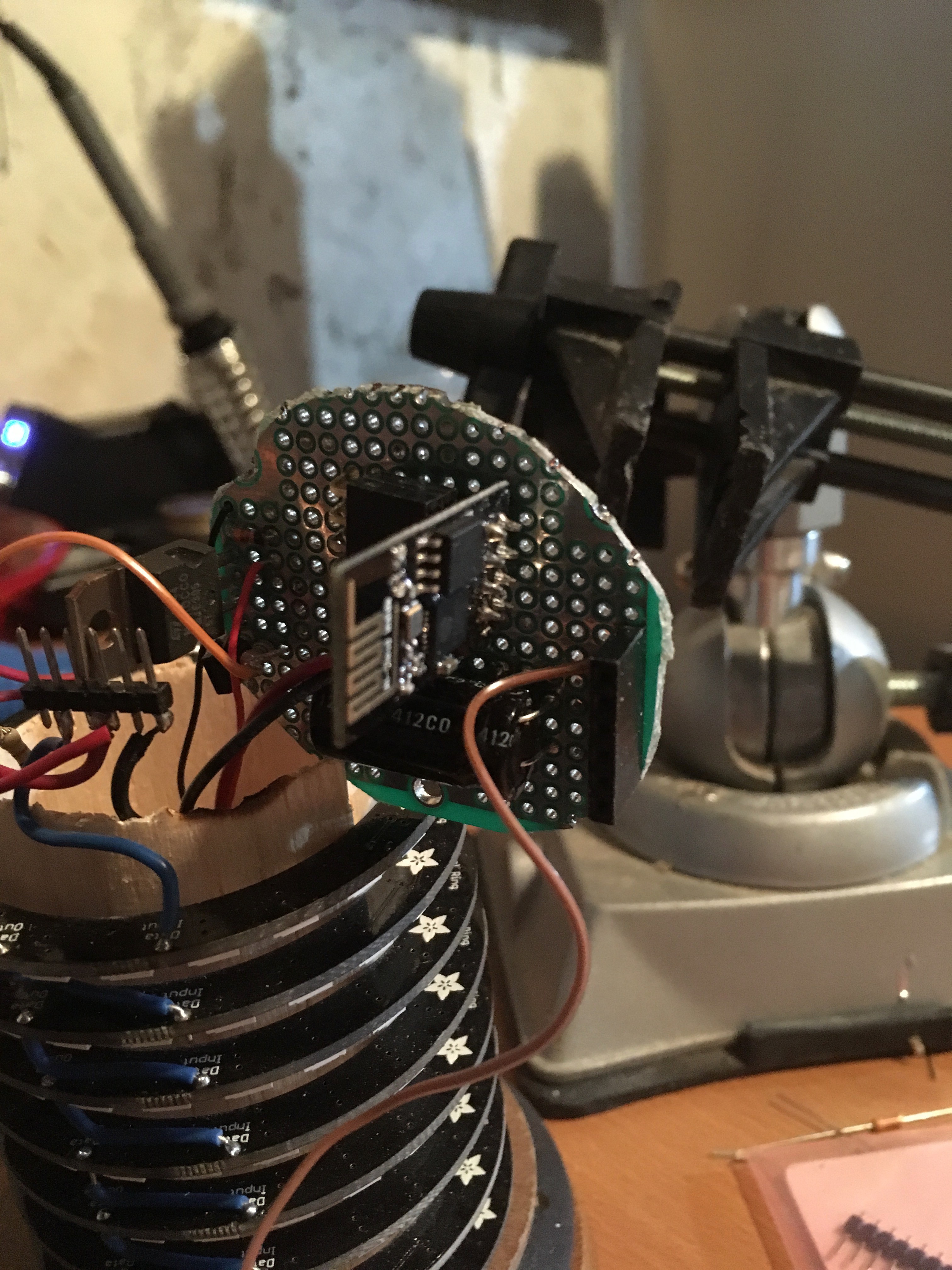
Step 2: rebuild around an ESP-01.
Step 3: ... find something interesting to do with the display?
Maybe step 3 is generally unnecessary. I'll focus on the first two...
![]()
Microcontrollers removed...
![]()
Board stripped down...
![]()
ESP-01 added...
![]()
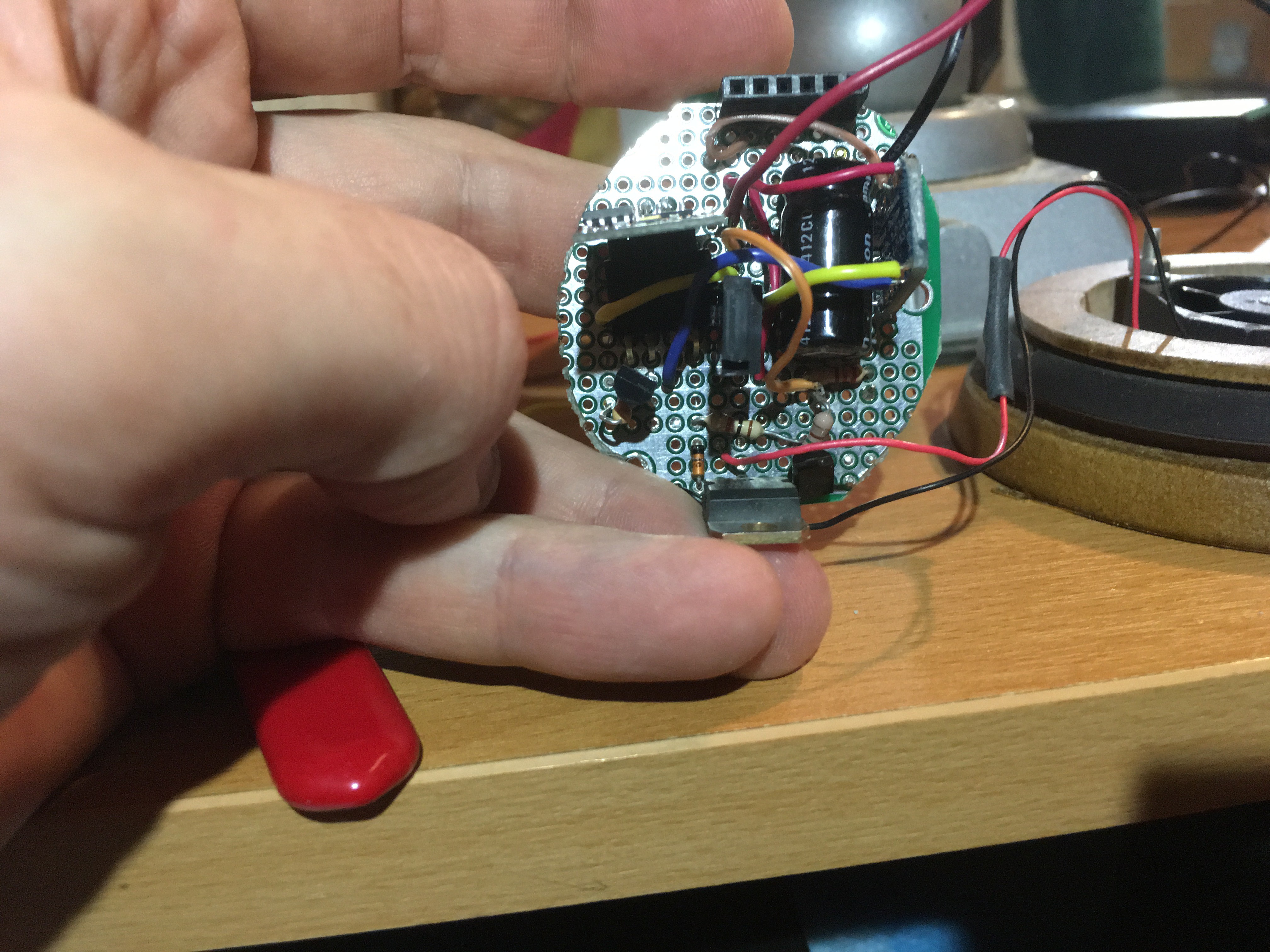
Fan wired back in.
Cool. A little programming later, and we're more or less back where I started - lights blinkin', purpose nonexistent. On the other hand, the microcontroller is now running at 80MHz with a proverbial boatload of RAM...
-
Part 9: share something already!
05/16/2016 at 12:31 • 0 commentsOkay, okay! For all the none of you that care about the actual code, I've finally published it on Github:
https://github.com/JorjBauer/purposeless-led-display
... I don't particularly want to share the encryption key that I'm using for this because, well, that's my flavor of crazy. I've finally expunged it from the archive, which means starting anew from this point on.
There are four subdirectories in the repo.
Gateway
The gateway (a Moteino with RFM69HW) is the "sending" half of the radio pair. It's directly connected to my Mac laptop via whatever TTL-serial-to-USB dongle I have sitting around.
Receiver
The receiver (a Moteino with an RFM69H and onboard flash) is embedded in the LED display. It shuttles packets back and forth from wireless to the Pro Mini "driver" via TTL Serial. It is also the timekeeping source when the display is in "clock mode".
Driver
This Arduino Pro Mini is responsible for running the LEDs. It expects commands over serial, and spits out replies the same way. Its bootloader has been overwritten, which means it can't be programmed directly via serial any longer.
Supporting
There are a bunch of Perl scripts in here that I use to send commands out the gateway. Many are just stub pass-throughs to Display.pm, but a few (like "programProMini.pl") are a little more complex.
-
Part 8: The Cycle (is too long)
05/13/2016 at 22:04 • 0 commentsAfter wiring up the static RAM, the next obvious step is, well, to test it. Right?
I wired in some test code that writes a %256 value to each memory location and reads it out; then displays a good-or-bad pixel on the LEDs. Good enough. And it works! Mostly.
Occasionally I get a failure right off the bat, and I can't figure out why. So, more debugging code inserted, and reprogram the device to try again.
Sadly, the reprogramming takes 5 minutes. Which is okay for a once-in-a-while update, but when I'm spending 5 minutes uploading every little test and I've only got 45 minutes or so to work with, that's a heck of a long time to wait.
So the RAM goes on the back burner, and let's diagnose why it takes 5 minutes to update over the radio.
Step 1: look at the protocol.
The HEX file is being sent in ASCII to an RFM69-equipped moteino. The remote end uses a custom protocol to pick that up, sends an ACK that contains the entire line received, store it in flash locally, and wait until it sees the Intel HEX terminator. Then it fires up an ICSP connection to the Pro Mini and programs it in one fell swoop.
Step 2: profile.
Turns out that most of the time is spent in the receiving of the HEX file. The programming takes somewhere around 6 seconds.
Step 3: profile some more.
If I take out the write-to-flash, it's not noticeably faster.
If I drop the contents from the ACKs, it's not noticeably faster.
In fact, I can gut all of the actual work - just receiving and replying is just this slow. Hmm.
Step 4: send less data.
Over a couple of days' lunch, I've rewritten the programmer to send binary data instead of the Intel HEX data. The packets are about a third their original length. And, once I found the mistake in my packing that data, it works just as well.
And is faster. We're down to 2 minutes.
Bonus: the write-to-flash step was just because it was convenient, not because it was efficient. I gutted that, and now it writes directly to the Pro Mini while it's receiving. Because the ICSP programming protocol isn't time sensitive (and this is why I decided to use ICSP instead of the bootloader), it doesn't really matter how long it takes to receive, parse, and write each chunk of code.
Not too bad. Now I'm back to my little red light showing that the RAM is failing to work, and I have one less excuse stopping me from fixing it.
Fortunately, my order from LowPowerLabs has arrived! Which means I can spend time wiring up two little RFM69 remotes instead of debugging this RAM...
-
Part 7: Scope Creep
05/11/2016 at 20:32 • 0 commentsI've been thinking about what to do with this thing. Sure, it works as a clock, as long as something sets the time over wireless once every few days to adjust for clock drift. And it has a number of fancy light show modes that are interesting. But that, apparently, is not enough. The purposeless display wants a purpose.
Brainstorming with a colleague, I came up with three ideas for interesting functionality.
The first two are interactive game modes where two players play head-to-head. If I'm going to write those then I need some remotes so that the players can, umm, *play*. So, parts on order, and I'll get to that eventually.
The third idea is a less interactive game mode: I'm thinking it would be interesting to have this thing play Core War.
There are just a few problems with that. How do we submit programs to it? With just an 8x24 display, how do we display the state? And with a generally expected core size of 8k (where each core "memory cell" is comprised of an opcode, some flags, and two potentially large integers - let's call it 8 bytes of data) how do we address all that in a device that only has 2k of RAM, most of which is already committed?
Hmm.
Well, the first two of those are tractable. Submission via wireless, clearly. Which suggests I could have a precompiler on my laptop generate RedCode bytecode of some sort and upload that. And the display is probably just a matter of having each pixel represent a large chunk of memory space, with some averaging of color or something-I-can-address-when-I-get-to-it. But the RAM would seem to be a show stopper.
Or WOULD it?
Step 1: brainstorm crazy idea. Check.
Step 2: make crazy idea feasible.
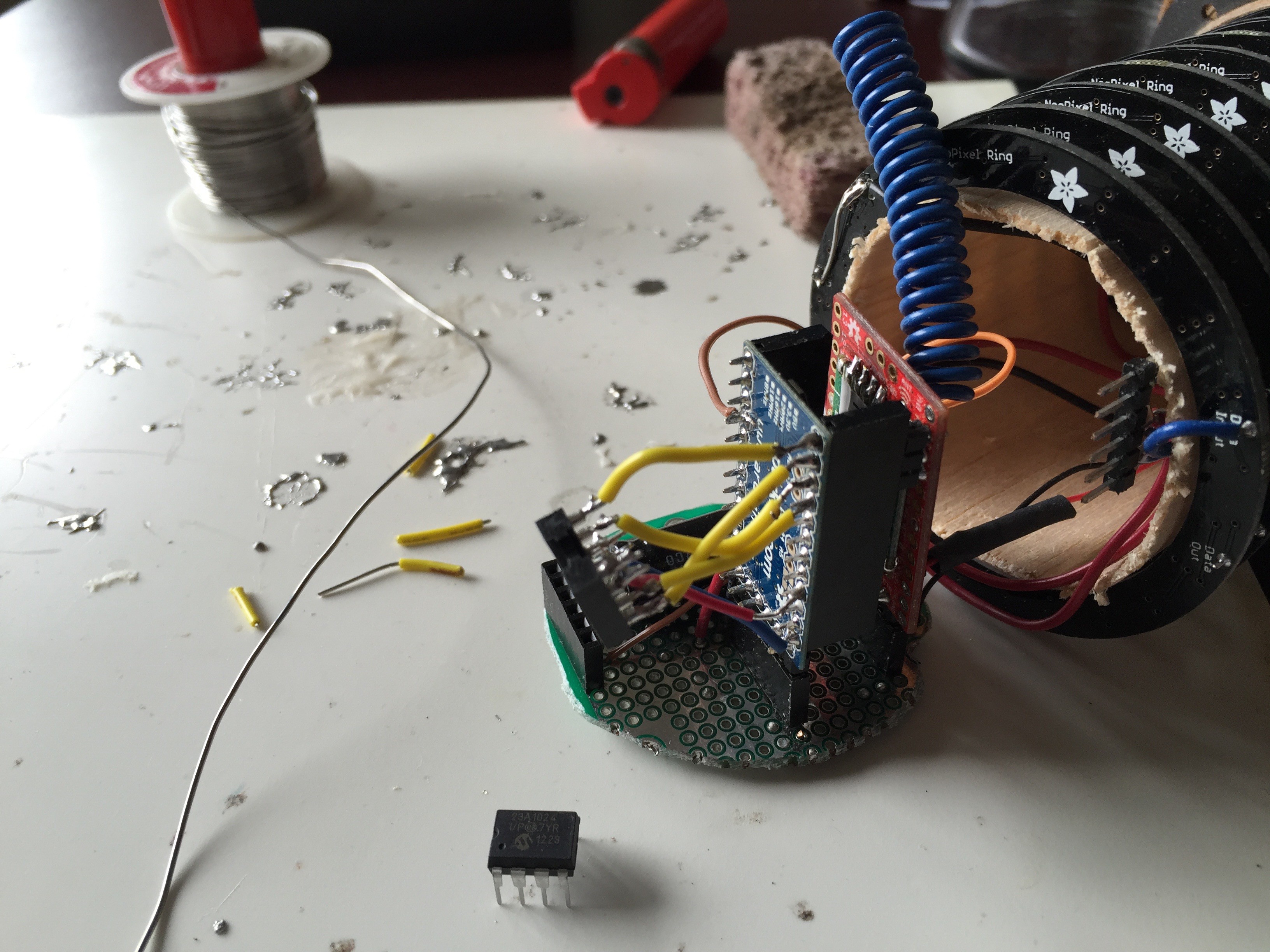
I've got some serial RAM DIPs sitting around somewhere. The 23LC1024 has 128KB (1024 Kilobits) of static ram. I could totally do something like
![]()
... yeah, that! - to throw it on the SPI bus of the driver, and then I just need to write some code to test that it works, spend a half hour wondering why it doesn't, and finally realize that - if you look at the photo really closely you'll see - I've put in a 23A1024 instead of the 23LC1024.
Sigh.
Bonehead maneuver accomplished. Probably destroyed that chip by putting +5v on the maximum-of-2.2v-as-specified-on-the-datasheet chip. Ah well, the price of progress! Onward...
-
Part 6: It's Alive! Or, at least, life
05/04/2016 at 19:42 • 0 commentsI'm slowly refactoring the code hither and yon - falling prey to the disease that Richard Feynman well described, where computer folks tend to play with the damn things forever. (This is, after all, a project I've given myself to work on during lunch, so I suppose that's warranted.)
The receiver, when I'm not accidentally bricking it by telling it to use the wrong frequency band, is working great. Taking a cue from the AT command set (which most readers probably won't know boo about; sigh) I have it interpreting "~~~" as a local command, where all other data is sent over to the driver. The driver communicates state back via serial, and then the receiver transmits that serial data back to the gateway node.
Shown above is a short time lapse of the Purposeless Display playing Life, one of the many modes I've chucked in to the code.
-
Part 5: Software? Maybe?
04/06/2016 at 13:33 • 0 commentsI suppose it's time to start talking about the software running this thing. But to do that I need to talk through the hardware some more.
My original design goals included:
* Use the parts I've got, as much as possible.
* Allow wireless programming so I don't have to open this once the hardware is stable.
So, as I've already mentioned, I decided to use an Arduino Pro Mini (5v, 16MHz) to run the LEDs; and a separate Moteino with an RFM69 and flash onboard. There's a single 5v 10A brick running the show (I didn't want to jam a DC-DC converter in the already-sahara-desert-conditions candle housing).
So the whole software design starts with programming.
If you go take a look at the LowPowerLabs github site (https://github.com/LowPowerLab/WirelessProgramming) you'll find that Felix already has a way to wirelessly program the Moteino. I love the flexibility of these little devices, and I'm ready to wax poetic here - not only do these make it easy for me to throw 5v at a 3.3v board and skip all the logic level shifting, but they let me reprogram them remotely? Sign me up.
If you look at the WirelessProgramming_node (in the Arduino programming environment's Examples -> RFM69 -> Examples) you'll see the hook buried in loop() - it's essentially this:
RFM69 radio;
SPIFlash flash(FLASH_SS, 0xEF30);

void loop()
{
  if (radio.receiveDone()) {
    CheckForWirelessHEX(radio, flash, true);
    // ... or go do something with your received packet if it still exists
  }
}
That CheckForWirelessHex() call will run the radio and not return to your code if it sees a magic "I want to program the Moteino now" packet. This abstracts the code reasonably well; while I would have preferred that it return some indication that it does its magic, I'm okay with it as-is. If it finishes receiving a wireless update it winds up resetting itself, so there's no real reason for it to return a value. I suppose. It just feels wrong.
Anyway, my coding preferences aside: now we have a Moteino that can be wired up and jammed in the housing, never to be seen again (well, mostly; see my post about adding DTR to a cheap PL2303). We just need to figure out how to wire it up.
I want two more things here. First: the Moteino has to be able to tell the Pro Mini what to display. Easy enough: let's wire up the RX/TX serial lines to each other (RX to TX both ways, and we can also read confirmation from the Pro Mini that it has read and enacted whatever we've told it to do).
Second: I never want to have to open the housing up to reprogram the Pro Mini. So I want to wirelessly be able to program it, too.
I thought about embedding the ArduinoISP sketch inside the Moteino's code, having it act as a wireless ArduinoISP programmer. I shied away from this because it wasn't clear to me that I'd be able to stick to the timing that this protocol expects.
Instead, since the Pro Mini has just one output pin (to control the LEDs), I figured I might as well take advantage of the other free pins! Using RST and pins 11-13, we can program the Atmel chip directly, bypassing the bootloader. Timing is very lax in this programming protocol, and I figured I could buffer the program in flash on the Moteino on its way to the Pro Mini.
Looking at the Moteino and Pro Mini and thinking about how I hoped to put them inside this housing, I figured that using Moteino pin 4 for RST and 15-17 for MOSI, MISO, and SCK (to connect to the Pro Mini pins 11-13 of the same) would let me put the two face-to-face and wire the pins directly to each other. Two sockets underneath them would give both boards power and ground, and connect the two serial lines TX-to-RX bidirectionally.
Fantastic. I just have to write some code to do the programming from the Moteino, which can wait until later.
As an afterthought, there's that fan I mentioned back in Episode 2 of this thrill-a-minute (perhaps I should get out more) build log. The fan is controlled by the Moteino, which has a temperature sensor in the radio (OH MY GOD IT CAN ALSO MEASURE TEMPERATURE I love these things and I should definitely get out more, shouldn't I?).
Once you've got an RFM69 object like above, it's this trivial to read the temperature from the radio module:
uint8_t temperatureC = radio.readTemperature(-1);
The "-1" is a user calibration factor. I figure I don't really care about calibration just yet, so I've told it to ignore my calibration and just tell me what it thinks. Maybe I'll come back around to look at how to properly calibrate this some other day.Oakie-dokie: I've got a temperature reading, and a fan. I want to control the fan's speed relative to the temperature. I mentioned a couple articles ago that I set this up with PWM and a couple of NPN transistors, so let me try to recount how this thing's wired up... from memory: the Moteino pin 5 goes through a 200-ish-ohm resistor to the base of a 2n2222. The 2n2222's collector is wired up to +5v through another 200-ish-ohm resistor, with the emitter wired directly to the 3055's base, and the 3055's emitter is wired to ground.
The fan has a diode (a 1n914 or 1418 or some other small signal diode that I had lying around and seemed like it would suffice for the reverse current of a small fan starting and stopping) across its leads, backwards. The positive of the fan is then wired up to +5v, and the negative of the fan is wired to the collector of the 3055.
Did I mention that the 3055 is extreme overkill? Why in the heck did I put a 70V 10A NPN power transistor in here for a 5v fan that's going to be pulling a couple hundred milliamps, at best? I have no idea. I must have been looking for a MOSFET and stumbled across this instead. This is typical of my projects, really.
Maybe I'll reverse engineer what I wired up and draw that out more seriously, but the words are good enough for now. It's all sort of loosey-goosey, and is a terrible model of a two-stage transistor buffered amplifier. Basically I tried driving it directly from the 2n2222 and found that I couldn't reliably get it to run, so I threw a second stage on it haphazardly. Meh, it works.
It's like my ability to speak German. After spending three weeks in Germany, my brain rewired itself for language. When I came back I found myself continually mixing metaphors. It was all about getting the general point across, rather than using the right specific words and phrases. In both cases, I'm well aware of what I've done wrong, after the fact: I just have no intent in going back and fixing it because it does its job well enough.
Anyway.
With that get-up I can drive the fan with a PWM from the Moteino. Pin 5 is open, so I use it. Now, with some definitions of when I want the fan to come on at low speed and when I want it at full bore (which are all guesses right now):
// degrees C
#define MAXTEMP 35
#define MINTEMP 25

#define PIN_FAN 5

uint8_t temperatureC =  radio.readTemperature(-1); // -1 = user cal factor, adjust for correct ambient later

if (temperatureC >= MAXTEMP)
      temperatureC = MAXTEMP;

if (temperatureC >= MINTEMP) {
  uint8_t fanRate = map(temperatureC, MINTEMP, MAXTEMP, 0, 255); // scale the temperature value to a 0-255 fan rate
  analogWrite(PIN_FAN, fanRate);
} else {
  analogWrite(PIN_FAN, 0);
}
One last hardware tidbit before we close up the enclosure and move on to software. Adafruit recommends a beefy 1000uF capacitor across the power leads to the LEDs. I'm not filtering the power from the power brick at all (I really should), but I did put in the 1000uF cap across the power feed where it leaves my board and heads out to feed the LEDs. I figured I might as well learn from what they've already (presumably) screwed up.
And with that, I think we can close this baby up and see if we can write software to make it do anything even remotely interesting.
-
Part the Fourth: Go Forth And Replace
03/31/2016 at 02:09 • 0 commentsSo speaking of Adafruit and value add: the heat is going to continue to be a problem for as long as the LEDs are touching that glass. So hows'bout we try a little something else?
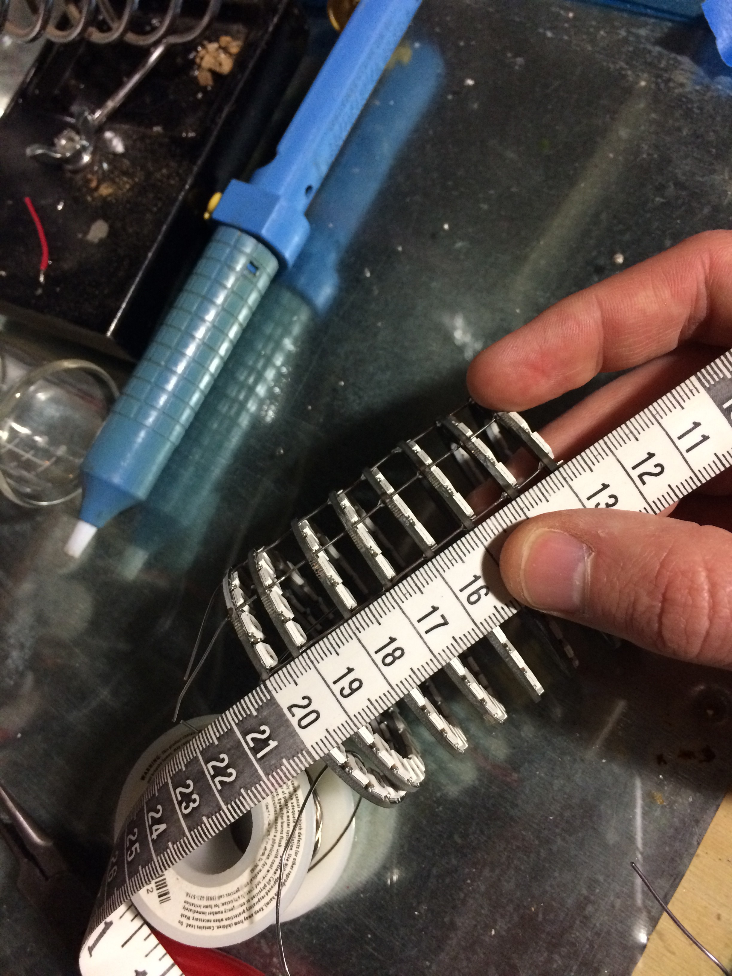
That's 8 Neopixel rings. So I'm going from 7 strips of 27 LEDs, to 8 rings of 24 LEDs: 189 to 192 LEDs total. The diameter of the rings is slightly smaller than the baking soda canister I had used to mount the WS2812 strips in the last iteration, so the air flow should be improved. And, coming from Adafruit, I'm pretty sure they'll have checked these out for faulty parts.
And, some soldering later, I jammed some balsa wood around the inside of the rings as a rear reflector, and here's what we've got:
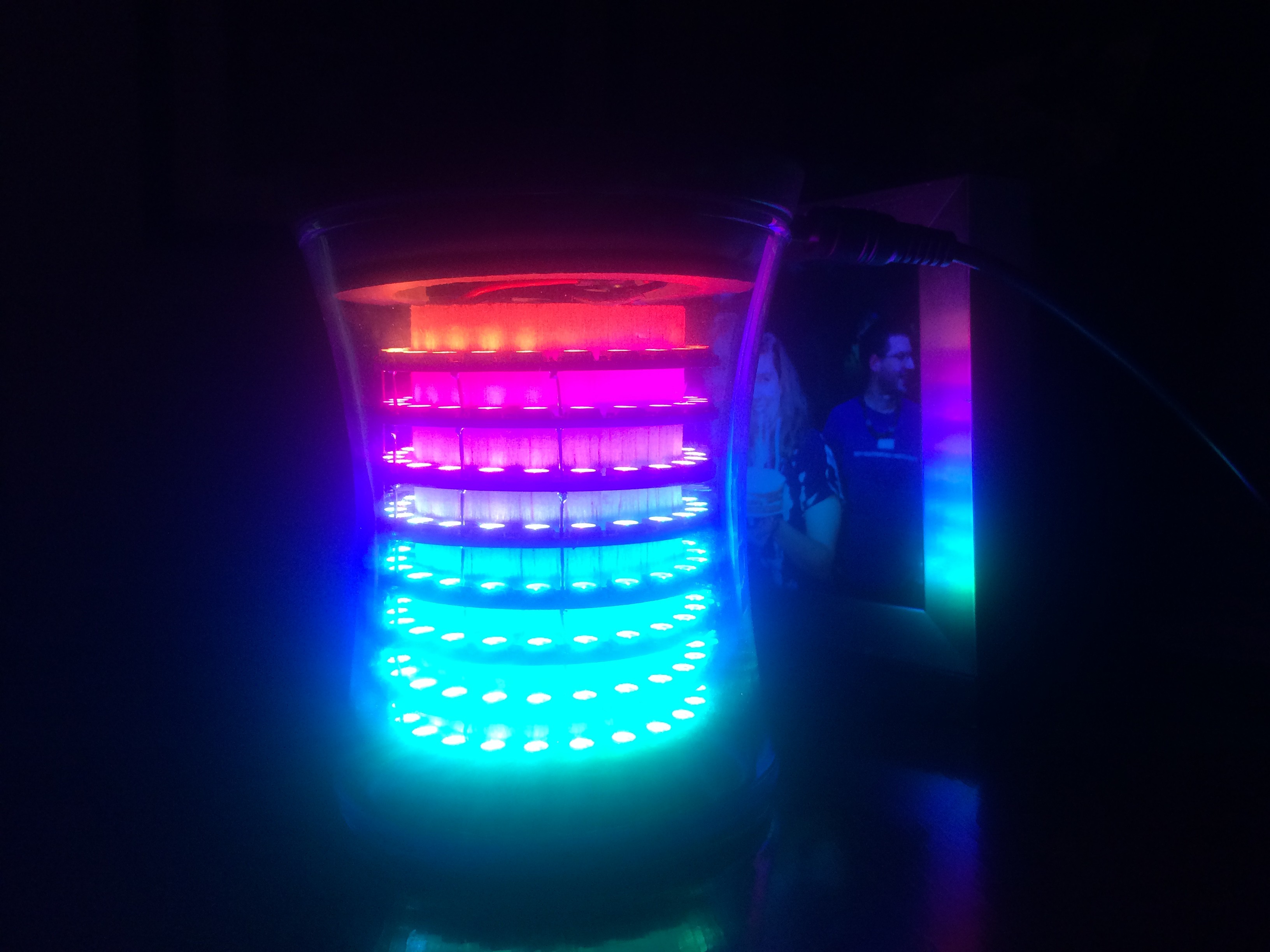
As usual, the LEDs aren't very good photographic subjects, but you get the idea: the LEDs wind up showing on the balsa wood if you're looking at them from on- or below- horizon. And from above, you get the full assault of the lights.
So far, so good. I've been tweaking firmware and playing with light patterns today, trying to convince myself as to whether or not I actually like this arrangement.
-
Number 3: The Microcontrollers
03/30/2016 at 13:30 • 0 commentsI should probably talk a little about the electronics in this build.
Yes, I chose a Moteino. The RFM69 with flash onboard. The frequency is immaterial (but I'm using 433 MHz). The flash was deliberate: when done, I want to be able to reprogram this thing via wireless, which you can do if you plop on the flash IC.
But there are two microcontrollers in there.
The Pro Mini has a pin driving the LEDs as a single strip. And the two microcontrollers have their RX and TX lines connected (swapped, of course) so they can talk RS232 to each other. I have a half-baked protocol that I've been using to control LEDs for my Christmas trees, so I used the same protocol here (yay code re-use!). And there's a pin on the Moteino that's being used to drive the fan via PWM (using the onboard temperature sensor in the RFM69 to keep an eye on the temperature, driving the fan appropriately).
But none of that lets me reprogram the Pro Mini wirelessly. That's a real problem I want to solve: I would hate to finish this thing off and find a bug, have to open it up to reprogram the Pro Mini.
Of course, the solution is obvious: use the Moteino as an Arduino programmer.
So: a pin on the Moteino is connected to the RST line of the Pro Mini, and pins 11, 12, and 13 of the Pro Mini are driven from the Moteino as well. With those lines it's fairly simple to implement the programming protocol. The one down side is that doing it this way blows away the bootloader. Which is fine: I just have to program the pro mini via the Moteino (or any other in-circuit programmer). I can put the boot loader back if I absolutely need to.
It works like this:
I compile code for the Pro Mini, and find the .hex file that was generated.
I have a (Perl) script that sends the .hex file, with some necessary header info to invoke the "programming mode" in the Moteino.
The Moteino stores the .hex file's text contents in flash as it gets them. When it detects that we're done (which, again, I did in a kind of half-assed way that's sufficient for now but makes me kind of uneasy) then it starts programming the Pro Mini.
Along the way I added a "reset the Pro Mini" command from the Moteino, so that I could reboot it if something weird happened; and I added some feedback while it's programming in the form of pulsing the fan so that I can tell when it has started receiving a program, when it starts flashing, and when it's done flashing and is rebooting the pro mini. Because there's no good way to get feedback on the LEDs while the pro mini is being reprogrammed.
Well, maybe "no good way" is a bit of an overstatement. It's certainly possible for me to flash bits of code, reboot the pro mini to execute it to show something on the LEDs, and then flash more bits of code. Repeat. But that seems like a lot of work for very little feedback.
The process is slow: I haven't optimized it at all. It takes somewhere around a minute to flash the pro mini. And there's a race condition somewhere that I haven't quite tracked down. But it works well enough for now.
-
Phase 2: heat remediation (aka "Quality Control? We Don't Need No Quality Control")
03/30/2016 at 13:18 • 0 commentsMy first attempt at heat remediation was: put some rubber feet on the bottom; drill two holes in the wooden plug; add a 5v fan that I had lying around, PWM controlled from the Moteino (so the Pro Mini can continue driving the LEDs full bore).
I had a 2n2222 at hand, and grabbed a 3055 NPN power transistor. The 3055 is totally overkill here: I'm talking about a 5v couple hundred mA fan, at best. The 3055 is rated for something like 20A at 75v. But I'm not using it for anything else, and this combination makes a fine fan driver (with a couple 200-ish ohm resistors, one on the base and one on the supply of the 2n2222; and the 3055 dumping current rampantly through the fan - yes, probably with some ringing that I don't really care about yet - and whatever diode I can find lying around to deal with the motor's current backrush).
As usual, I've totally bodged this together. I didn't sit down and plan it, so I didn't draw out a schematic. I didn't put it on a proto board. I just soldered it all up dead-bug style and jammed it in the cylinder to see if it worked. And voilà, the fan sprung to life!
With no demonstrable improvement in heat load. The fan was just some 20mm DC fan I had lying around and really didn't move enough air. Off to Mouser, then, and a suitable high-CFM 5v 35mm fan was bought.
Now, I'm trying desperately to keep the wood plug on the bottom. I like how it looks with the glass exposed on top. But I realize this is a terrible idea for reasons of physics (convection). I really want to let the heat out the top. And to make it worse, where I had planned to mount things to the wooden plug, I now had to make a substantially larger hole for this fan.
Okay, okay, it's finally time to give up on the plug-on-the-bottom. I flipped the whole thing over, and this is where I actually start taking pictures. The components all get a circuit board as a home; I routed a nice hole in the plug, and filled it with some perforated black aluminum. The fan screws on to the aluminum, and now I'm thinking that there's a good amount of air flow (6 CFM max, which my back-of-the-envelope heat load calculations say ... well, that I have two unknown variables and I can't possibly solve the equation, so I give up and figure I'll see how it goes).
With the fan running well, I figured I'd spend some time repairing the pixels. Of course, at this point I've used up my spare 144-LEDs-per-meter WS2812b strips, so I have to actually spend money on some. So I find a cheap supplier and get them somewhat slowly.
Friends, there is a problem here. There are two price brackets for the same product: you can spend $30/meter for these from suppliers, or $60/meter from resellers. That kind of markup always makes me go the cheap-but-slow route. Well, let me tell you: order them from Adafruit at $60/meter.
The first problem is counterfeits. In this case, that means LEDs that have excessive heat load (or 2812s that are being sold as 2812bs). Which maybe you can tolerate, or maybe you can't. And maybe you find the good suppliers that are using the good WS2812b, so it's not a problem.
The second problem is the real kicker: about 2% of these LEDs are DoA. About 3 per meter. A little research shows that this is typical for these buggers. If that's truly the failure rate, then companies like Adafruit must be putting a ton of staff time in to testing, replacing, and returning the defective runs. No wonder they're marked up so much. All of the LEDs I'd started with were from Adafruit, because reasons: they're in New York, I'm in Philly; Lady Ada is awesome, and I want to support her business; Adafruit makes great materials available to novices, which I think is really important for budding electronics nerds. So I had absolutely no problems with the 2m that I had lying around from early Christmas tree light tests.
But these replacements *suck*. I wound up spending hours replacing individual LEDs, splicing together larger runs, removing the old dead runs from the cylinder and putting in place new runs - just to find out that the new runs worked well under light load, but had substantial problems when they ran full-out. Heat failure was very common, even with more massive airflow (outside the candle holder). Some pixels appear to have mechanical problems, not having been soldered on the strip very well, and slight heat variations cause them to fail. This is, in short, not a working solution.
Time to think about a better solution.
-
Initial design (aka "What Junk Do I Have Lying Around?")
03/30/2016 at 12:52 • 0 commentsThe actual candle pictured here - before being burnt - is a "large" Woodwick candle. That's not the container I'm actually using, but I don't have any more "medium" candles lying around.
This seemed like a fun thing to build; I have no particular purpose for it, but I have a bunch of WS2812 (and 2812b) LEDs lying around. So one night, I rummaged around our house looking for something that could support these LEDs inside said container.
The closest cylinder I found was a baking soda container, whose diameter was just a hair too large. So I emptied it out, sliced it down the side, and - you can just see this in the picture with the solder side of the LEDs - glued it together so it would be a bit smaller (E6000 glue, if you really care). Then I spraypainted it black, waited for it to dry, and cut up the strips of LEDs to the right length.
The LEDs are hot-melt-glued on to the cylinder. Now, I know these LEDs are going to throw off a lot of heat and hot melt glue probably won't be the best choice, but at this point, I have some serious questions about whether or not this is going to work. I figured that the soldered wires would be a fine mechanical restraint, at least to get some bearing on the project. And so far, that's been true.
The control circuitry, then.
I've done a bit of WS2812 controlling. For the past two years, we've used them as ad-hoc Christmas tree lights, with some nice patterns and colors that we all enjoy - driven by an OctoWS2812 coupled with a Moteino, so that we can wirelessly control the light patterns. This year, my son set up a small tree in his room too and wanted more lights: so we set up a small strand of WS2812s driven by another Moteino. So I have some history and - dare I say it? - infrastructure to support these.
I figured I wanted to build this out of junk parts, so I didn't really want to go buy another Teensy and OctoWS2812. I have a bunch of Moteinos, and some Pro Minis, so I thought it would be sufficient to drive this thing from a Pro Mini and communicate over RF with the Moteino. (I assumed, right or wrong, that a single Moteino would be underpowered for high-speed display changes, and I still had no idea what I wanted to do with the final display, so two microcontrollers made some sense.)
All of this, generally speaking, worked fine. It was December and we're some combination of crazy and cheap; our house runs about 62 degrees Fahrenheit. This thing puts off a bunch of heat, but not so much that it seems a problem. Particularly when the lights aren't on full bright and constant. I orient the candle so the wood top is now the bottom, jam all the parts inside, and it looks pretty good.
And then I set it up on a window where the sun shone in.
The candle, of course, acts like a greenhouse. There's no airflow through this thing. And the WS2812s do, as I had at this point forgotten to deal with, put off a good bit of heat. So when they hit something like 230 degrees F, they began to fail. Bringing me to remember about heat load and dissipation. Riiiight.
But the point is proven. I like how it looks, and I figure it's just a matter of dealing with the heat load - a couple holes and a fan, replace some dead pixels, and I should be golden. Boy, was I wrong...
Purposeless LED Display
When life gives you an empty glass candle holder, why *wouldn't* you jam a ton of LEDs in it?
 Jorj Bauer