Tobias
-
More Power Saving
05/24/2016 at 23:29 • 0 comments![]()
![]()
![]()
![]()
58.4mA 459.7mW 53.2mA 418.3mW Could a different buck converter save power? The DROK Analog USB uses 40mW more than the lower board of the DROK Buck Converter 5V-30V to 0.8-29V.
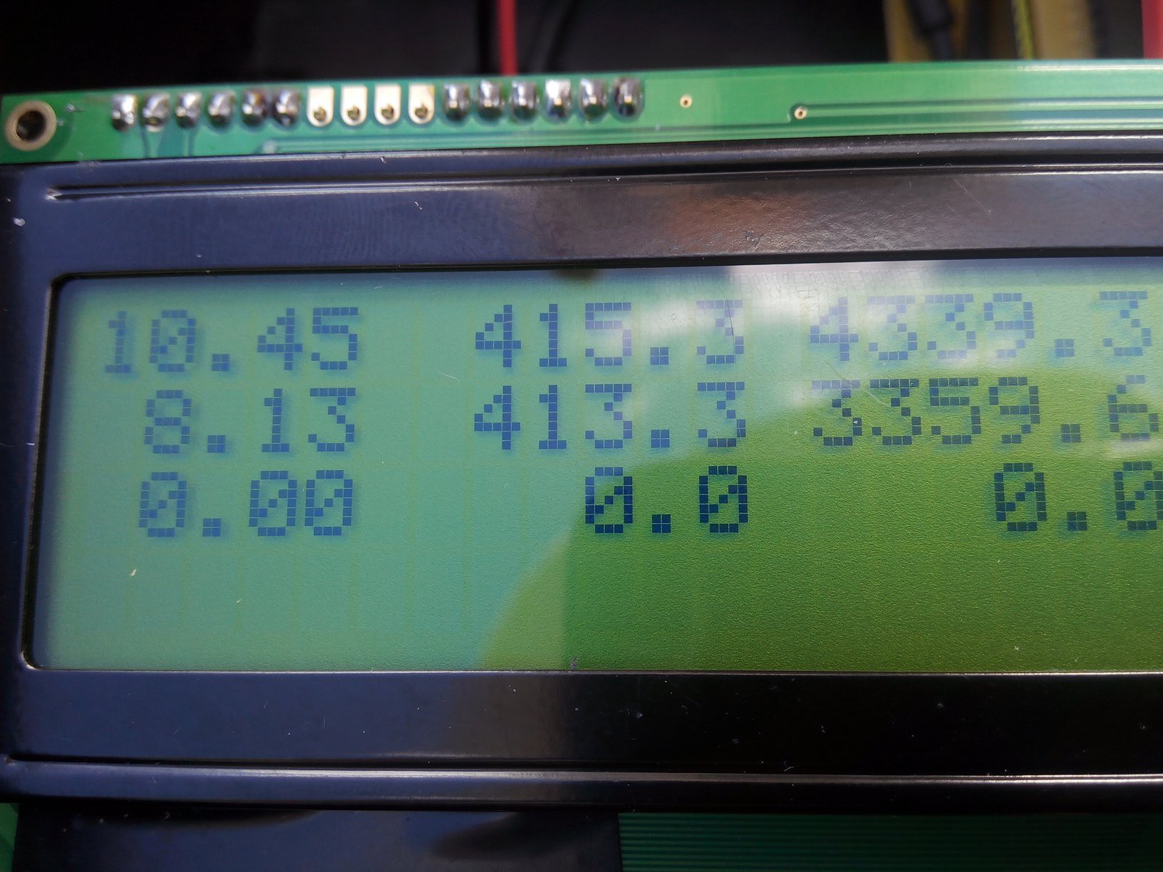
Turning the PWM off when it is not needed saves 3mW:
![]()
![]()
PWM on: 418.3mW PWM off: 415.3mW Finally, from https://youtu.be/urLSDi7SD8M
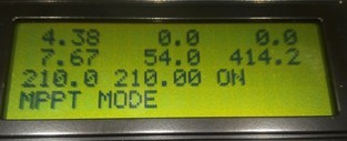
Letting unused digital IO pins on the Arduino not float (set as output, input, or use pullup resistors) can save 4mA!
![]() Some floating pins
Some floating pins![]() No floating pins
No floating pins54 mA 414.2 mW 50.8 mA 389.7 mW -
Power Consumption Improvements
05/22/2016 at 02:09 • 3 comments![]()
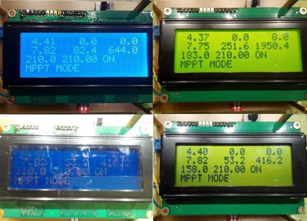
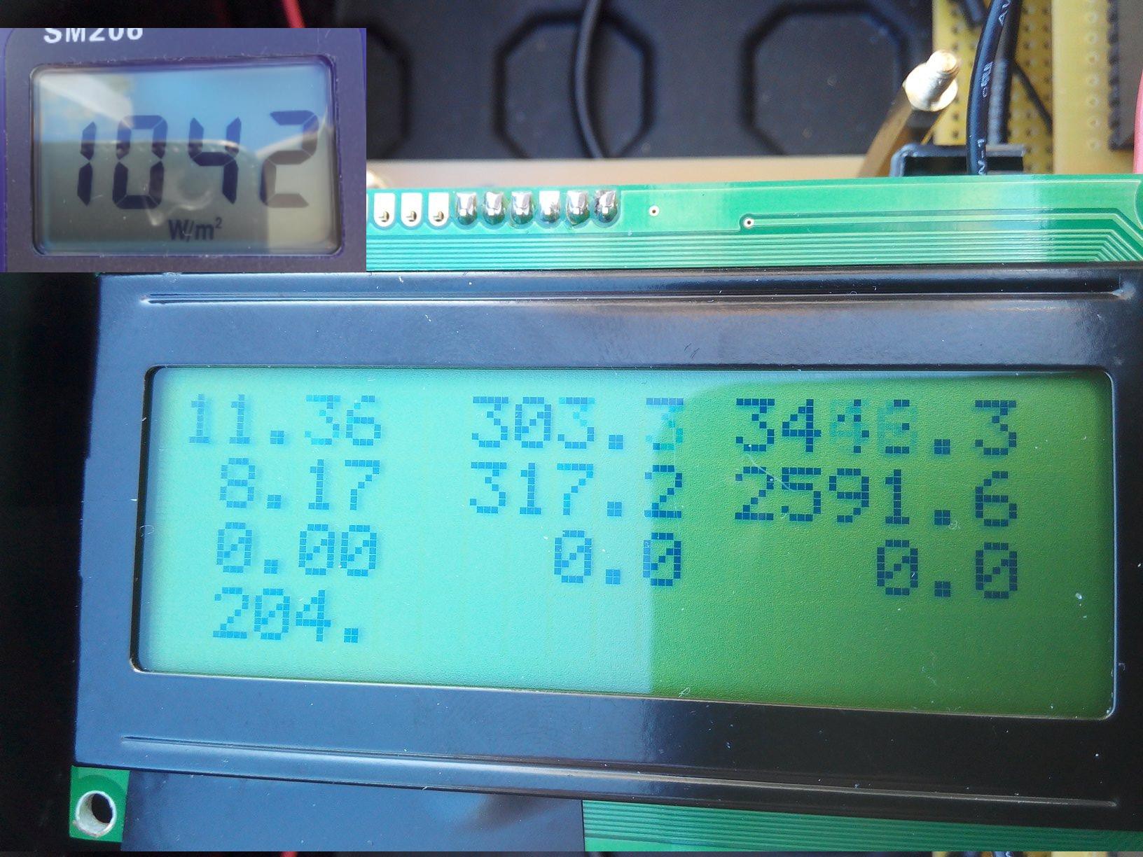
LCD Backlight Analysis:
Current/Power blue LCD transflective (sunlight readable) LCD backlight on 82.4mA 644mW
251.6mA 1950.4mW
backlight off 53.2mA 416.2mW
53.2mA 416.2mW
The LCD backlight turns out to be a real power hogger. 1950 milliWatts? Whoa!! Maybe I should read the datasheet more often..
240-280mA! I thought I had a short circuit, but apparently, this LCD uses that much current for the backlight. From now on, the backlight will be off in my circuit (cut pin 15 to the display), but I added a switch, just in case.![]()
-
Autonomous Solar Powered System
04/29/2016 at 00:03 • 0 comments![]()
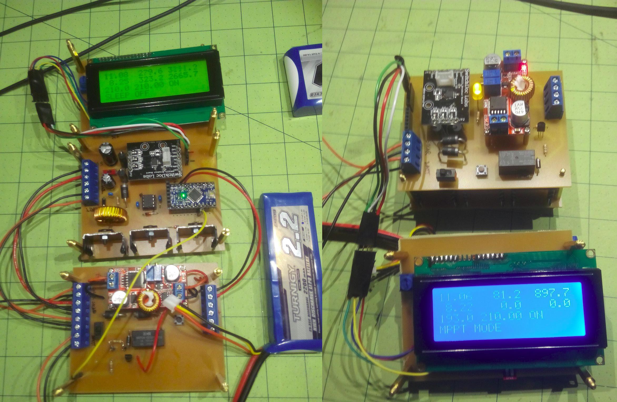
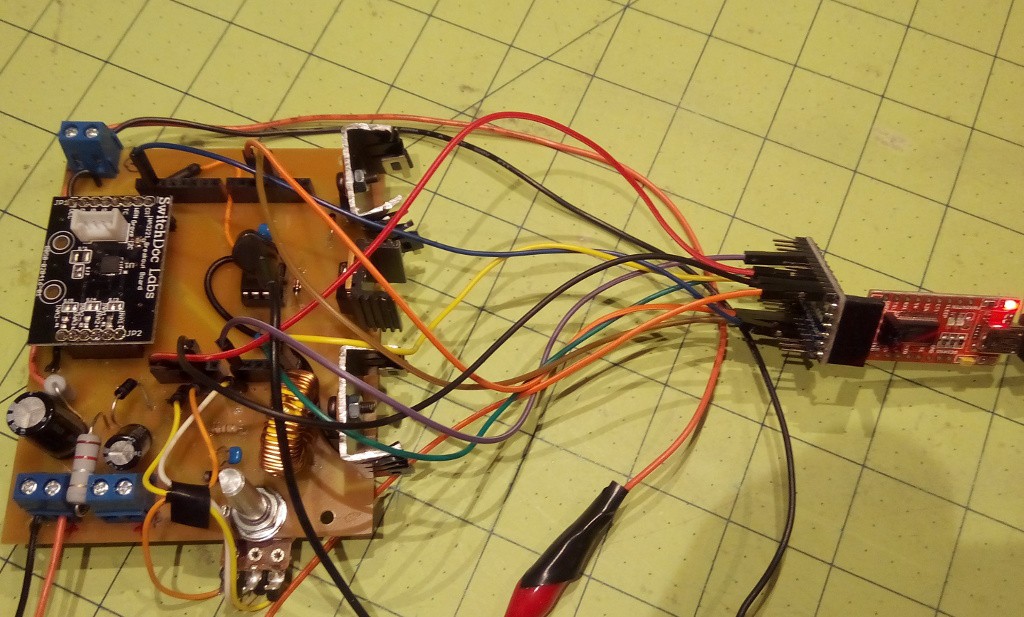
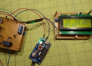
The MPPT charge controller works pretty well by now, but there are a few more steps necessary to make this an autonomous system that does not require human intervention. I added a power controller board that takes care of that. To reduce internal cables and screw connectors, I added two Arduino headers that quickly connect and disconnect the two boards (picture on the right).
One of the important aspects is that the battery will not get drained over time; for that purpose, I added a relay that completely disconnects the battery when its voltage drops below a threshold. The relay itself is powered by the Arduino through a transistor.
The system can be powered up either by the solar panel (when the sun comes up and sufficient power gets into the buck converter which turns on the Arduino) or by pushing the button that bypasses the relay until the Arduino keeps the relay powered on.
In principle, it should be possible to use this design for a planetary rover that spends days, weeks, or months inside a container without sunlight and wakes up when the solar panels receive sun light. It continues to work even after the battery has deteriorated.
-
External Voltage Regulator and Buck Converter Efficiency
04/28/2016 at 22:40 • 0 comments![]()
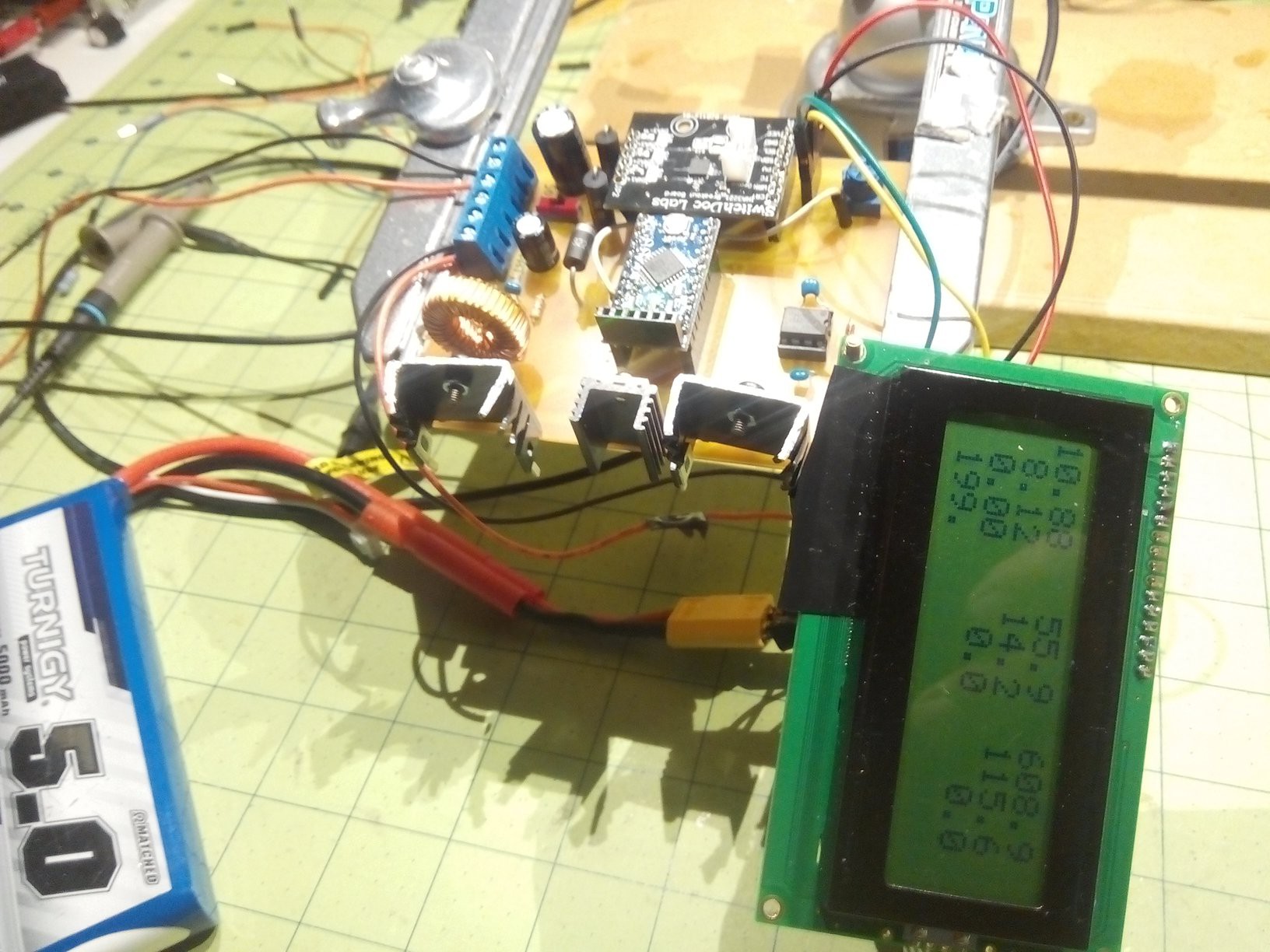
I damaged another Arduino Pro Mini, due to overloading the internal voltage regulator. Time to try something different. (The Arduino still works, as seen in the picture, except for the RAW input). Let's supply the Arduino with 5 Volts on the VCC pin, rather than around 8 Volts on the RAW input. This will also free the Arduino Pro Mini from having to supply the power for the INA3221 board and the LCD.
As a first approach I tried a 7805 linear voltage regulator which works, but is very inefficient.
![]()
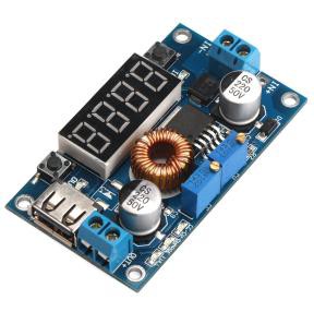
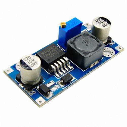
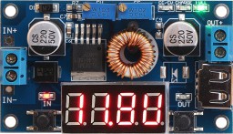
So I decided to use one of the buck converters which I had tested in the past. The advantage is that I can use the 5 Volts from the same buck converter for the Arduino as well as the load which is a Banana Pi. So only one buck converter in the whole system.
Efficiency:
DROK Analog with USB
![]()
![]()
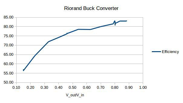
Riorand
![]()
![]()
-
First Prototype working
04/23/2016 at 23:29 • 0 comments![]()
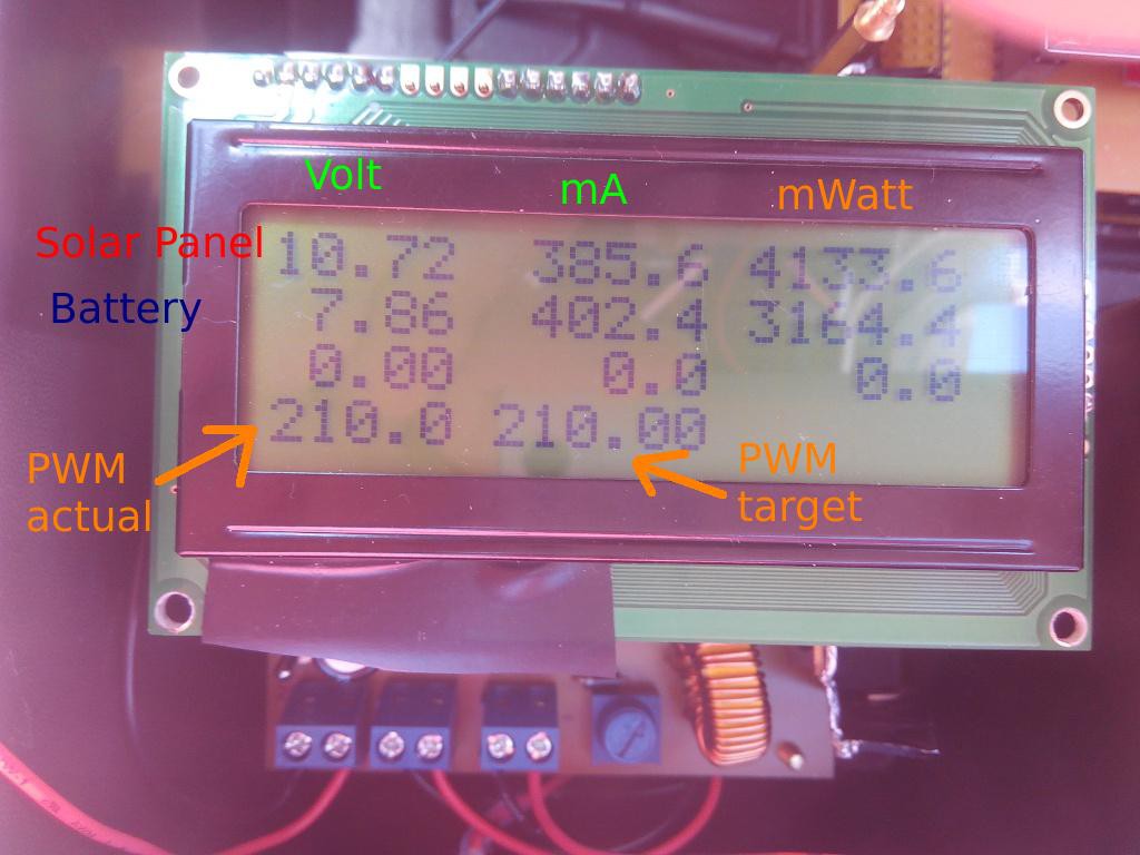
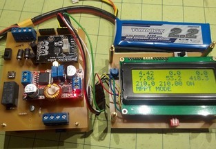
I started working on the Arduino software that measures the voltages and controls the PWM duty cycle. Two functions have to be implemented: Limiting the charging when the battery is full, and setting the PWM to the maximum power of the solar panel during charging. Protecting the battery is priority, so I started on that first. For a first approach, I set the charging PWM to fixed 210 which means 210/255 = 82% which I found from previous testing to be very close to the actual maximum power point in full sun light.
In a first attempt, I told the software to charge at full 210 PWM when the battery voltage is below 8.4 Volts, and 0 PWM when the battery voltage is above or at 8.4 Volts. Not a good idea-the abrupt switching from 210 to 0 and back destroyed the Arduino Pro Mini.
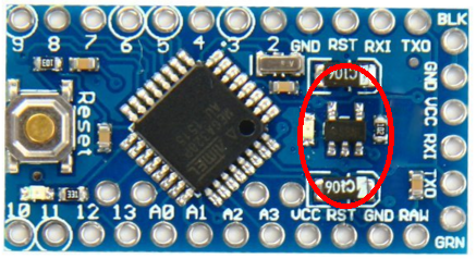
![]()
The marked area got very hot, probably the voltage regulator. Fortunately, I paid only $2.80 per Arduino.
To fix the problem, I introduced a hysteresis function such that the software computes a target PWM value, based on the battery voltage, and changes the current PWM only by one in each pass through the loop (loop delay at about 0.5 seconds).
Software at
-
LCD works, enough power from Arduino Pro Mini
04/19/2016 at 23:12 • 0 comments![]()
![]()
I did not expect the LCD to work in addition to the INA3221 power monitor on the I2C bus, but it does. I am powering the Arduino Pro Mini with an 8.4 Volt Lipo 2S battery on the raw pin, and an internal converter turns out 5 Volts, apparently with enough milli-Amps to run both my I2C devices. Very convenient during development. Here are some measurements of the current from the battery:
- with LCD: 39mA at 8.1 Volts, PWM=169/255, solar panel disconnected
- without LCD: 23 mA at 8.1 Volts, PWM=169/255 solar panel disconnected
- without LCD: 20 mA at 8.1 Volts, PWM=169/255 solar panel connected
- without LCD, with green LED on Arduino on: 29mA regardless of whether solar panel is connected
So the LCD draws about 15-20 mA, the green LED 5-10 mA. Without both, it is 20 mA.
The bottom line is, without bells and whistles, the board can do its job for about 160 milliWatts. Later: There are a lot more tricks to reduce power consumption of the Arduino Pro Mini.
-
Further Arduino Pro Mini Testing
04/19/2016 at 00:14 • 0 comments![]()
An Arduino Pro Mini was connected instead of an Arduino UNO and testing was sucessful. Time to make a new board specifically for the Pro Mini.
-
Going Arduino Pro Mini
04/16/2016 at 01:35 • 0 comments![]()
I did some preliminary testing to find out if I can replace the Arduino UNO with a less power-hungry Arduino Pro Mini.
PWM signal generation on pin D3 - works
Reading power values from INA3221 through I2C - works
The Pro Mini doesn't really have to power an LCD in the long run. If it can do that, great; If not, no problem. I don't really want to waste power on an LCD for a solar charge controller anyways. So far, this is looking pretty good.
-
New Design
04/16/2016 at 01:22 • 0 comments![]()
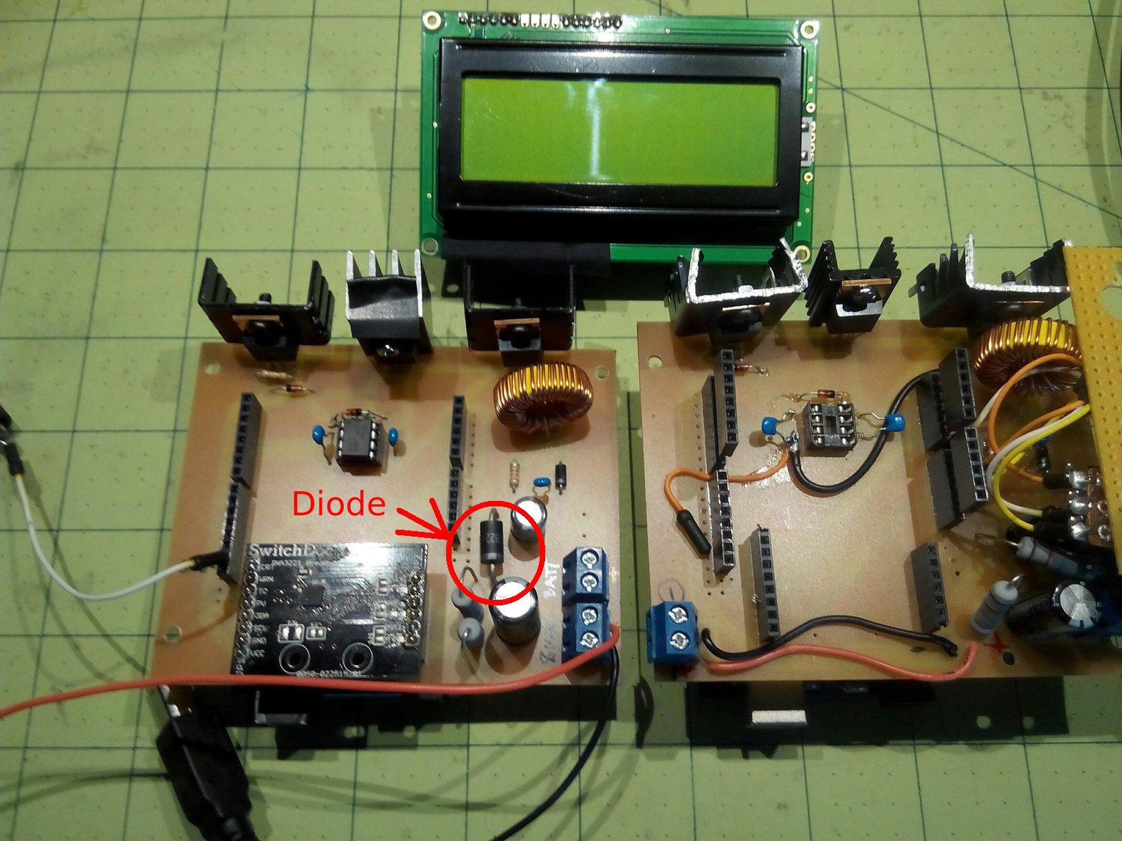
Previously, components were destroyed by high currents battery flowing back into the circuit. I added a diode which works well and the circuit is now much more robust.
The drawback is that efficiency has dropped from 88% to 78%.![]()
![]()
full sunlight, 1370 W/m^2
![]()
-
Destruction Derby
04/15/2016 at 00:48 • 0 comments![]()
I noticed that when a battery is connected and I turn the PWM to a low duty cycle, a negative current flows from the battery into the cicuit. The current can get very high, here 1.35 Amps, even more than 3 Amps. A few days ago, I turned the potentiometer to a low PWM duty cycle setting and then I heard a pop. Here is the destruction tally:
1 IR2104 chip
1 INA3221 board
1 Arduino UNO
1 diode
Obviously, the design has to be changed.
I suspect that when the output voltage of the buck converter is lower than the battery voltage, the gate of the MOSFET Q3 is still open, but the battery now pushes current through the MOSFET to ground. There is almost no resistance, which can lead to high currents and the destruction of components.
One possible solution would be to keep the PWM high enough through software, but that setting depends upon varying conditions. It is much easier and safer to just add a diode that prevents current from going into the circuit from the battery. A 1N5822 Schottky diode costs me a voltage drop of about 0.3 Volts, which is not bad, but still reduces the efficiency of the circuit. Eventually, I want to look into the technique of using a MOSFET as a diode which can reduce the voltage drop.
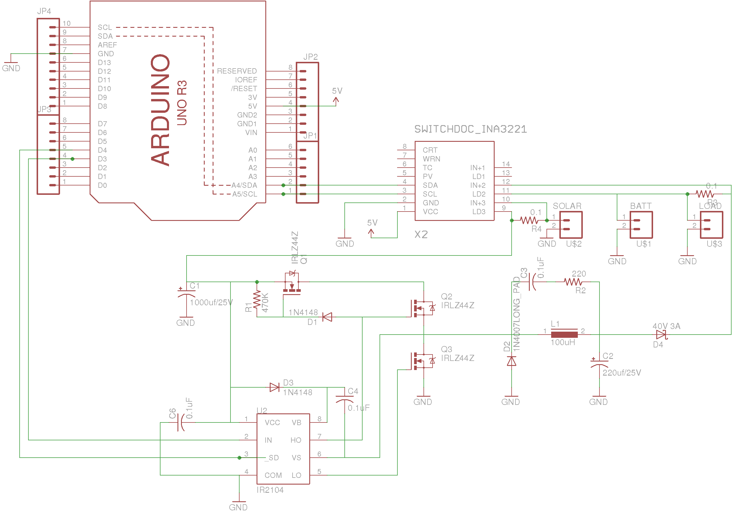
Arduino MPPT Solar Charge Controller
The charge controller consists of a buck converter that is controlled by an Arduino via a half-bridge driver.


 Some floating pins
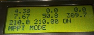 No floating pins