 Adrian
-
1Step 1
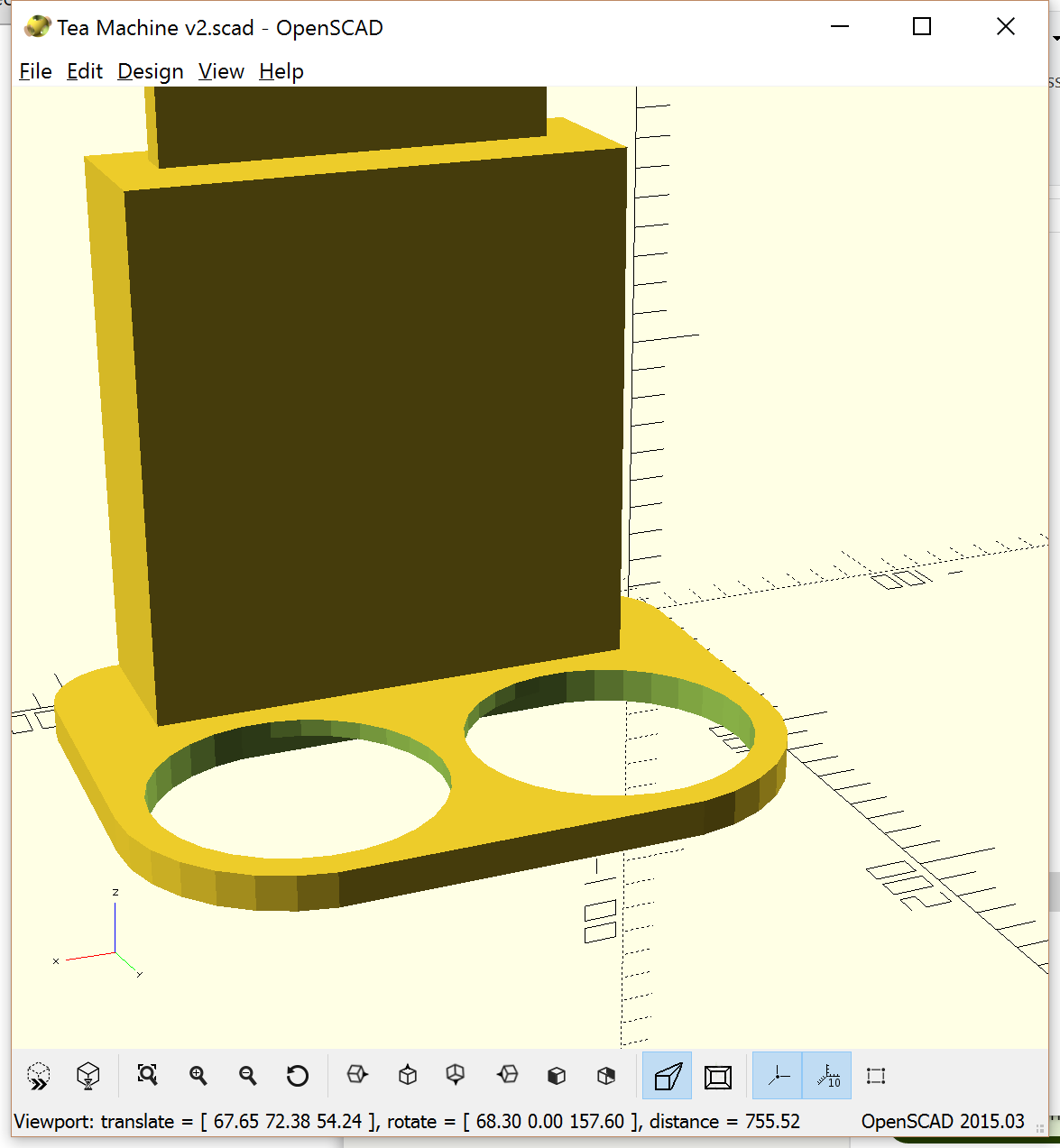
I'm putting all the design files I have for this project on github - so far I've got the model for the box which although 2D Laser cut, was designed in Openscad. I actually use this along with Slic3r to generate Gcodes that drive my RepRap powered K40 Laser.
![]()
-
2Step 2
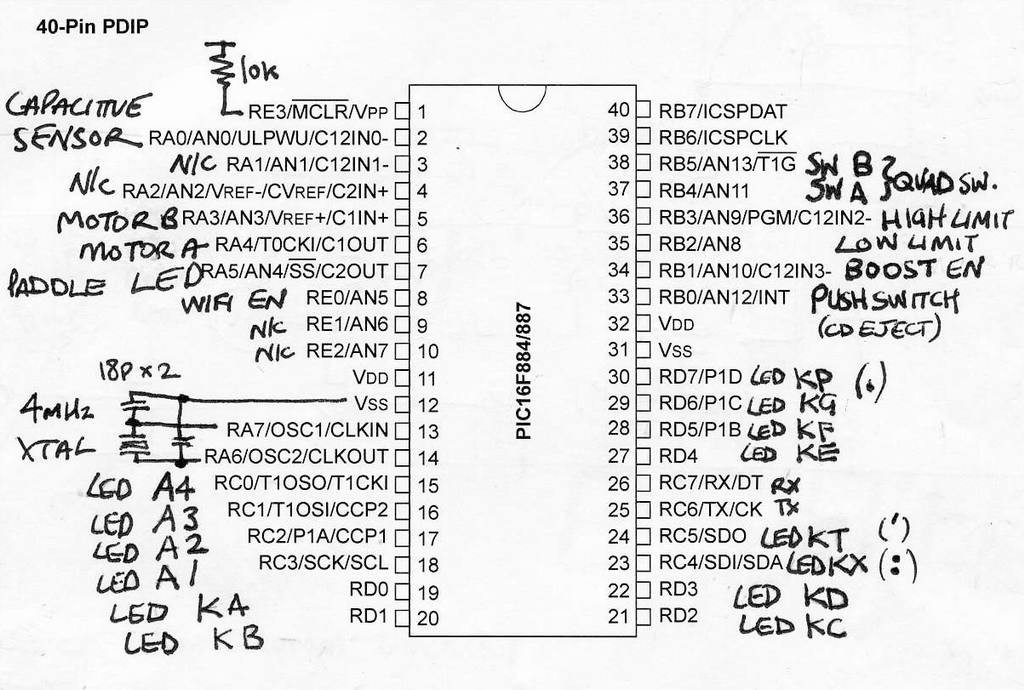
While the CAD files for the case should be good for all types of CD Drive, the electronics are going to have to fit in whatever space is left after removing the bulk of the original CD mechanism. All that's retained is the tray and front portion containing the motor, limit switch and eject button. Because of this and the fact that our one-off was made on stripboard, no PCB design is available. If you want to reproduce ChaiBot you will have take a similar approach or make your own tailor-made PCB layout.
One trick was to size the stripboard vertically such that the two battery holders squeezed in between the board and the end of the case. Three hand-drawn circuits provide everything except the detail of the rotary encoder and connections to the CD eject button. The firmware assumes that these three switches are all commoned to 0V.
RB6, RB7, Vpp, VSS and VDD form the ICD programmer connections and are not shown. You will probably have your favourite connection method anyway.![]()
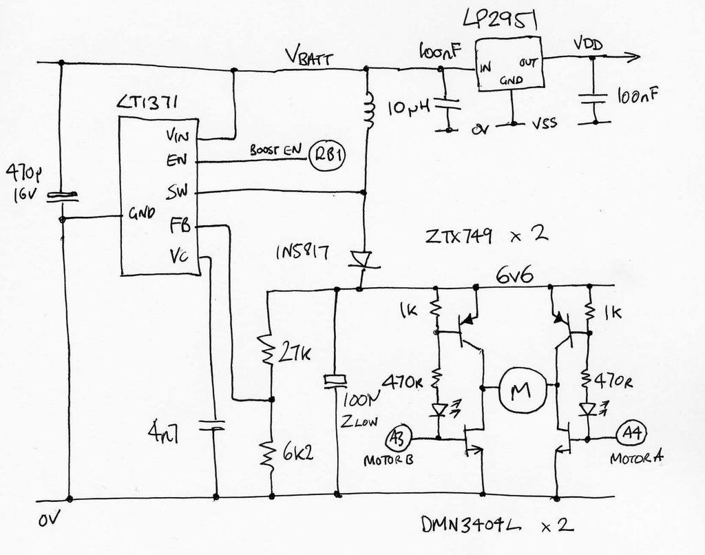
The two PNP high-side transistors could be replaced with P-Channel Mosfets. We didn't have any to hand at the time. The LED's (red) are there to drop ~2V to prevent turning on the PNP's when the RA3, RA4 are high ~5V and also serve as test indicators ;-)![]()
![]()
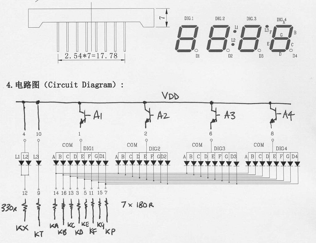
The display requires four NPN transistors connected as Emitter Followers to buffer the PA pins driving the common anodes. We used 2N2222 but BC182, BC548 etc. are all good here.
-
3Step 3
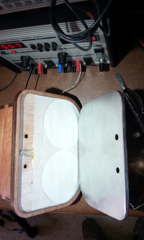
The sensing of filling and removal of the cup(s) is handled by a capacitive weight sensor. A small screened lead connects between the PIC and a pair of thin aluminium plates. The active plate is situated below the two cup recesses and is glued to the underside of the uppermost plywood base part.
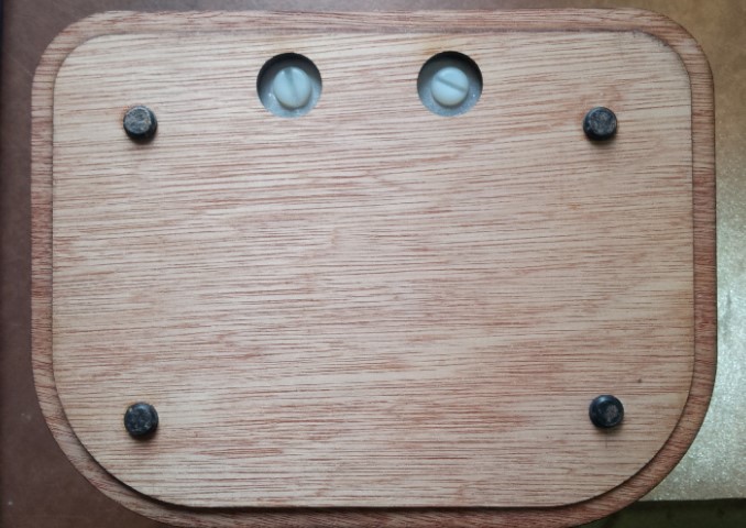
The lower part of the base is composed of a thin perimeter glued to the upper part and the remaining inner cut-out section which is free to move within the perimeter (using the clearance provided by the laser cut). This supports the ground plate and the two plates are separated by paper masking tape. Four rubber feet on the bottom of the inner base part ensure that all the weight of the device is acting to push the plates together.
![]()
To keep the coupling of any external electric fields to a minimum the underside of the cup recesses only have two joined circles slightly larger than the recess, while the ground plate is the full size of the base board. This shields the sensor plate from the worktop on which the device is placed.
A loop of the outer screen of the connecting lead serves to make contact with the ground plate at the back edge when the base is in position - while the central conductor (just visible under the paper masking tape in the photo) joins to the sensor plate in the middle. This join can't be soldered to aluminium (which is what we used) but tin (e.g. buiscuit tin) might be an alternative material. In the case of aluminium we just stripped the insulation back a couple of cm and splayed the conductors out under the sticky tape.
In operation 5V is applied to the top plate which builds up an electric charge between it and the ground plate then, when the voltage is removed, a timer is started and frozen some time later by the tripping one of the internal PIC comparators as the charge drops below a threshold. The time taken to discharge is proportional to the capacitance of the two plates which in turn is influenced by how much weight is squeezing the two plates together.
While the two plates aren't actively sprung apart, their loose proximity is enough to make a relative measure of applied weight. One detail that may not be present in the CAD files are the locations of the two holes for the large Nylon bolts used to secure the CD drive in the box and retain the base plate.
![]()
The position of these may vary depending on the type of drive used. We hot-melt glued two nylon nuts in the base of the drive to accept the bolts. The optimum location should be found and the holes added to the Openscad designs or they could just be drilled after assembly.
Note that the nylon bolts prevent the base plate falling out altogether if ChaiBot is lifted and clamp the plate to the cable screen but also allow the small amount of movement needed to sense the force from applied weight above.
-
4Step 4
The C source for the PIC16F887 is tailored for the CCS compiler. Hopefully it wouldn't take too much effort to convert for other compilers however the compiled .hex is also provided. The only include is a library for displaying ASCII on the four-digit LED display. The #defines at the top of this file were lifted from somewhere, somewhen long ago (I think it might be Linux). We're abolute novices when it comes to licensing and attribution so any advice is appreciated. The intention is that anyone is free to use our design in whatever way they wish.
-
5Step 5
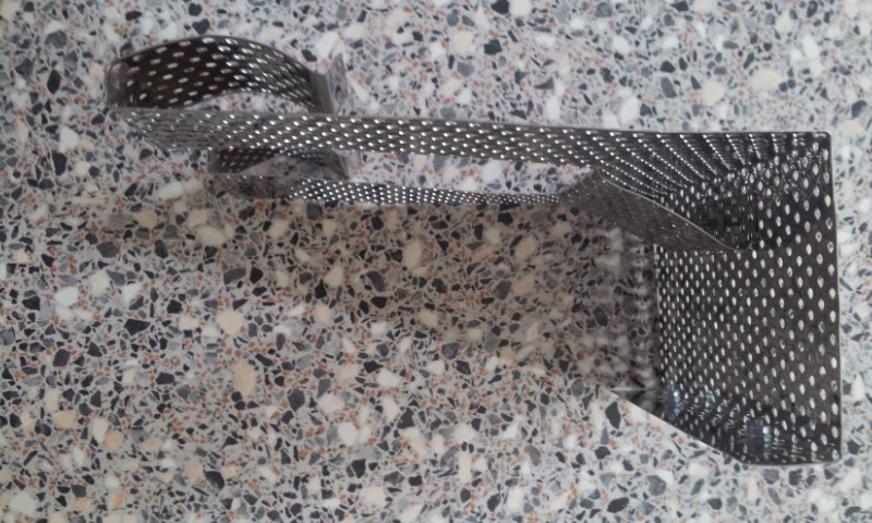
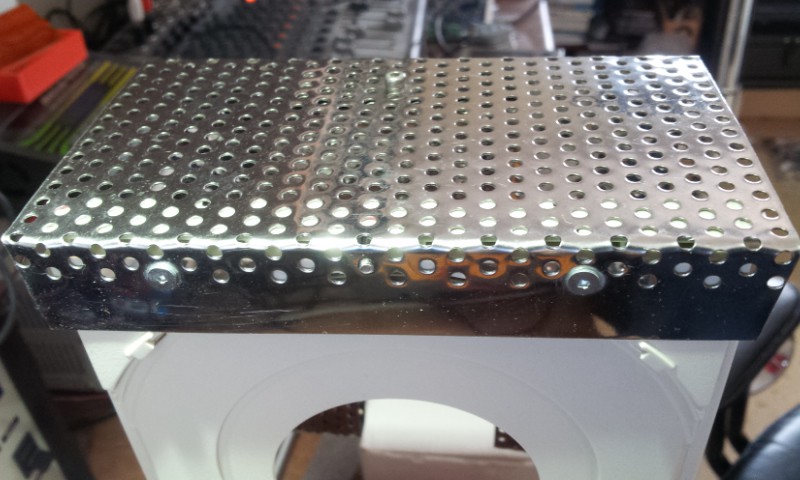
The gantry that's used to raise and lower the teabags was made from 0.5mm thick perforated stainless steel sheet bought as a barbecue accessory. It was cut with sharp scissors and folded into shape as shown:
![]()
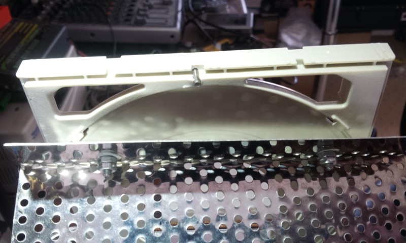
This was formed "on the fly" with no design drawing but started out as a 127mm x 305mm rectangle. The fold at the top edge simply hooks over the CD tray and is retained on a pair of nuts & bolts that locate into cut-outs on the tray as shown below:
![]()
The bolt protruding from the middle of the CD tray was also added to positively locate the mesh on the tray. The following photo shows how this aligns both parts. In use, the gantry can easily be tilted forwards and up off the CD tray for cleaning.
![]()
The rectangular slot in the paddle for the tray doesn't give much clearance so the bolt heads need to be filed almost flat (as we did) or swapped for countersunk types.
ChaiBot
Tea Steeping robot that starts a timer when cups are filled with hot water and lifts bags automatically to make perfect tea every time.
Discussions
Become a Hackaday.io Member
Create an account to leave a comment. Already have an account? Log In.