Adrian
-
Calibration
04/03/2016 at 10:56 • 0 commentsThe capacitive load sensor readings can be monitored and a detection threshold set for cup sensing (both for auto timing & auto shutoff) by entering "test mode". This is performed by pressing the paddle switch and holding it down until TEST appears on the display. A reading of something around 1000 should be expected without any weight on the cup base and the value should go up as cups and water are added (or you simply press down on the base).
While in test mode, turning the rotary encoder will alter the stored threshold setting. This value defaults to 200 but can be adjusted to suit the build. This threshold is used in two places:
- After empty cup(s) are placed and the gantry is lowered, the capacitive reading (weight) is noted. The threshold is now used to detect the pouring of hot water to automatically start the timer. I.e. weight has increased.
- When steeping has ended and the gantry is automatically raised, the threshold is used to determine when the cup(s) have been removed. I.e. weight has decreased.
Because of 2. a three-second delay has been introduced before the gantry is lowered following cup removal detection to allow time for both cups to be removed. A possible refinement would be to use the weight increase (as measured between the point when the empty cup reading was taken, and at the time when steeping terminated) and only perform auto shutoff when more than half this weight was removed.
To exit test mode (and as general rule to shut down the device) press and hold down the paddle.
-
Initial fettling
04/01/2016 at 21:30 • 0 commentsWith the initial design, the power supply was just 4xAA feeding the PIC + motor bridge etc. The idea was to eliminate the need for a regulator as the batteries could be expected to be between 1.6V max and 1.1V min. and by introducing a silicon diode in series with the battery supply, we get battery reversal protection and a 0.7V drop to keep Vdd within safe limits. This worked fine with fresh batteries but after around one weeks use the gantry motor didn't get enough power to lift two wet teabags.
The volt-drops were all adding up: e.g. 1.3V at each AA minus 0.7V diode drop meant only 4.5V was feeding the Vdd rail. 0.2V in the PNP side of the H-Bridge plus another 0.4V lost in the steel battery springs (has anyone else noticed how resistive these things are?) all conspiring to make the motor stall out.
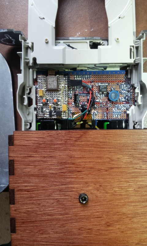
Handily, I've acquired a few tubes of LT1371 Boost converters so the solution was to boost the battery supply up to a regulated 6V and regulate the 5V for the PIC with a Linear LDO. This was all made using SM parts soldered on the back of the stripboard:
![]()
Top right: SM LT1371 legs splayed out to match 0.1" stripboard - works for me.
Top left: ESP8266 add to provide IoT capabilities - naturally.
ChaiBot
Tea Steeping robot that starts a timer when cups are filled with hot water and lifts bags automatically to make perfect tea every time.