The main things to be done are:
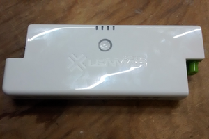
- Conversion of 8xC size battery holder to hold a standard 4x18650 USB power bank
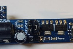
- Adding a 5v to 12v DC-DC converter to run the speaker from the USB power bank
- Adding a car Bluetooth module to the line-in port and mounting internally
- Adding some way of controlling all these devices so they can be mounted in the cabinet
First step was to dismantle the speaker - this is done by prising off the fabric grille and undoing the screws. This reveals the hot glue abortion that is inside. Luckily there is plenty of space.
I decided to mount the USB power bank in the battery compartment - this is a sizable 8 x C cell compartment so easily fits the bank with the removal of the cell row dividers.
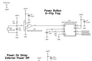
I then got to work on the logic board - basically I want to be able to press the power button on the speaker and have everything else turn on for me. So I set up a small logic board with a microcontroller. This then connects to three relays, one turns on a DC-DC converter to power the speaker, one presses the button on the speaker to power it on, and then one presses the button on the bluetooth module.
I also connected to the bluetooth module LED so I can tell what state it is in by measuring the pulses with it.
The rig on cardboard is the main circuit to do all this - the logic board with the relays and DC-DC - this connects to the bluetooth module (which will connect via a 3.5mm jack for audio to the speaker's line-in). It also connects to an RGB LED to give a status update to the user, and also connects to a switch to put it in to pair mode. And additional set of volt-free contacts simulates a pressing of the power switch on the speaker.
The basic mode of operation is controlled by a state machine in the PIC which has the following states:
- POWERING UP
- POWER ON, NO BT CONNECTION
- POWER ON, BT CONNECTED OK
- PAIR PREPARATION (preparing BT device for a pairing)
- PAIR WAITING (waiting for a device to pair)
- REBOOTING
The user interface consists of:
- Power button on speaker now connects to power button of USB power bank. (When this comes on, the PIC will do the rest in terms of powering up devices).
- RGB LED (mounted behind the grille somewhere) will indicate the state to the user.
- A switch mounted on the back or similar to initiate a pairingAt this stage most of the software has been completed using the cardboard rig, the project is currently awaiting installation of the device into the speaker. The speaker's switch has been modified to turn on the USB power bank, and the volt-free contacts from the logic board are awaiting connection to the speaker's logic board.
Why relays etc? Because they provide volt-free contacts and are easy to use. This is a multi-voltage system and I didn't want to mess about with isolation etc.
Why a PIC16F88? Because I had one laying about - it's a touch overkill and you could get away with pretty much most 14 to 18 pin PICs. It also just about supports debugging and has an internal oscillator, and has two 8-bit timers. FOSC in this project is kept at 32.150kHz to minimise current use since it's pissing current away in LEDs and relays already!
 Stefan Kratz
 Dan Julio
 TEC.IST
