xkcd.com/now clock in hardware
as I work with people all over the globe, I need a simple way to tell their local time without hanging lots of clocks on my wall
as I work with people all over the globe, I need a simple way to tell their local time without hanging lots of clocks on my wall
To make the experience fit your profile, pick a username and tell us what interests you.
We found and based on your interests.
I started this writeup/log with a plan in my head, but not written down here in detail. It looks like it is time to take a step back and look at the whole picture...
A quartz clock epoxy blob contains the following logic (more or less):
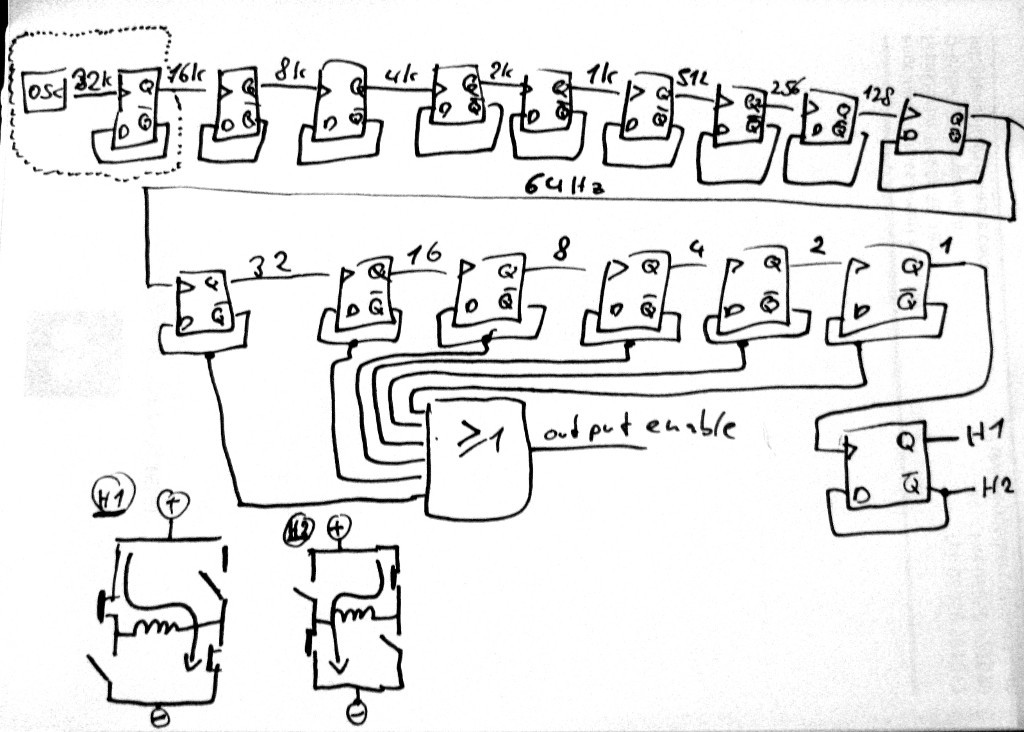
We got an oscillator (with support from an external quartz crystal), a whole bunch of frequency division stages and at the end a H-bridge which drives the electromagnet. A half evolution of the electromagnet moves the second pointer 1 second forward. All this bases on the exact time input from the oscillator/clock crystal which is 32768Hz +/- 0,00...% . The electromagnet is driven in short pulses to reduce power consumption (see "output enable" signal in figure above).
If such a clockwork needs conversion from 12 to 24 hours, the easiest way to achieve this is to reduce the input clock frequency to 50%.
It is not as easy as to just put another clock divider stage in there. As all this is buried on a chip in a black epoxy blob it is not possible to access this logic structure without huge effort.
Due to the way quartz oscillators are built, it is possible to just feed an external frequency into one of the pins and let the circuit run on this frequency.
See the following sketch for a detailed standard-logic-ic replacement of the dotted area in the figure above:
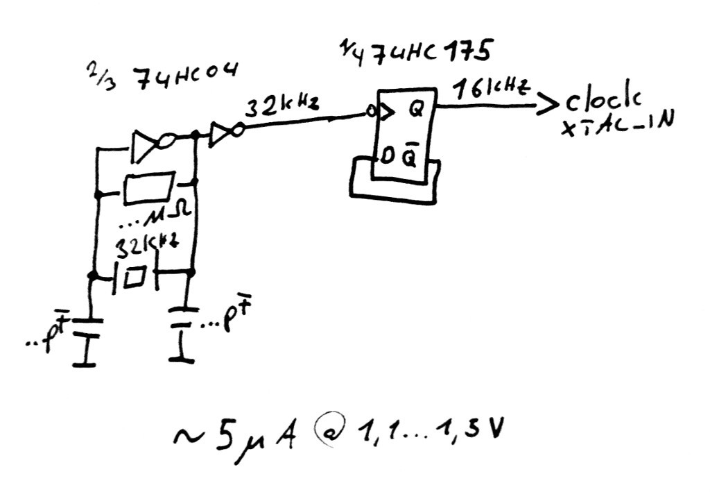
If the quartz is left out on the inverter IC, it is possible to just feed a signal in on inverter input.
My initial plan was to re-create this circuit, but replace the 74HC175 flipflop with an ne555 non-retriggerable monoflop with a monoflop-time of a tiny bit over one period of the 32kHz input. As the ne555 is just overkill for this application I decided to spend a few cents on a bunch of 75HC175 D-Flipflop from old stock (datecode 1988...) and go that route - sorry, the ne555 was just for the search hits :P.
The following screenshot was taken from the circuit above (yellow: current consumption in uAmps, blue: circuit output / 16kHz)

As the inverter and flipflop are cmos based, the current spikes occur at the same time as the logic gates switch. High spikes show the flipflop and inverter switch at the same time, low spikes show the inverter only. The average current consumption boils down to approx 5uA.
Connected with the clock and zoomed out the following picture appears (yellow: current in uA, peak mode enabled to fight aliasing):
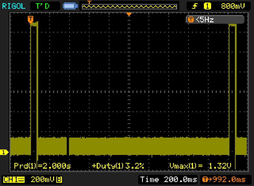
The bold line on the bottom shows the logic ICs switching. The big pulses at 2 sec period (clipped - ucurrent runs on 3V battery) show the drive magnet spin.
The circuit is built in 3d prototype construction technique for now, a flat perfboard design will follow.
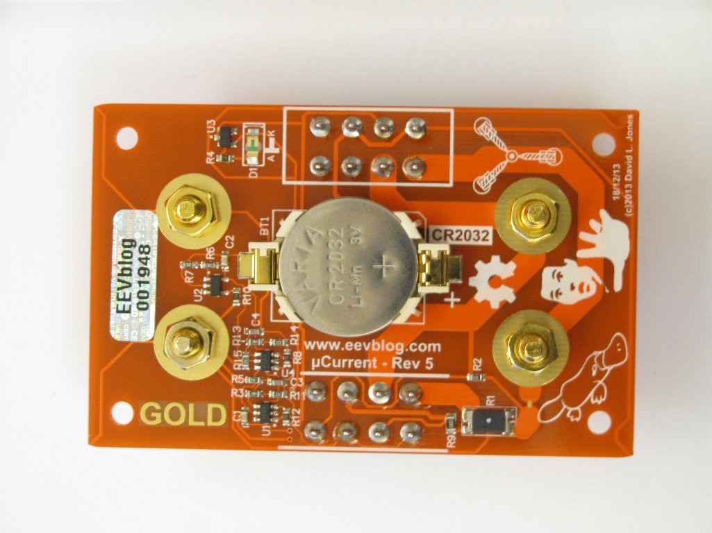
Finally, I received a letter to inform me that a parcel from Australia waits for me at the next customs office - uCurrent \o/
For German customs, you must provide info on what the value of the product is (read: all you paid for it, including shipping, transaction fees etc). If this info is not included with the parcel (e.g. because the sender has no clue what transaction fees you paid), you have to provide that info in person. Best way to prove this is to print out the relevant info from paypal, remove irrelevant info with a big black marker and run the result thru a photocopier. If "all you paid (until now)" is below approx 21 Eur, you don't have to pay any fees or taxes. For everything above that, but below a higher limit, they charge you 19% MwSt (=~VAT), but no Customs fees. If you get caught speeding on the way to a customs office, this costs an additional fee...
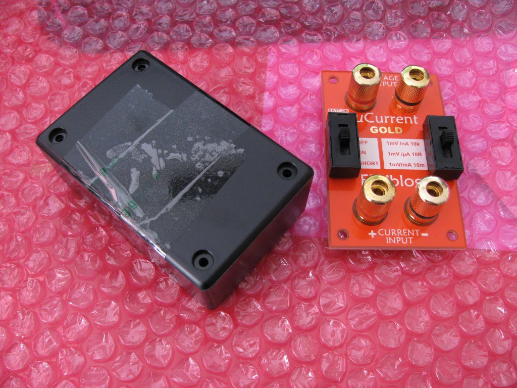
The uCurrent comes in two parts: PCB and housing. The housing contains the four screws and is held together with tape. Of course they had to look inside and and close it with "inspected by customs" tape, which is really sticky. Thank you -.- I'll try to get a refund from them for the time I lost removing that glue without damaging the enclosure...
CR2032 installed...
Measuring the current consumption of one of these continuous clockworks (their noise and power consumption make me go crazy...):
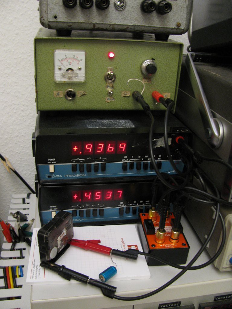
The power supply with the nice lockable multiturn dial (~5 Eur , flea market find) provides 0.94V, the clockwork consumes avg. 454uA. The big blue cap at the clockwork helps on averaging and provides stable readings. This clockwork consumes half a milliwatt.
"You could fly to the moon on that!" -- Dave Jones, EEVBlog
Anything else around I can test out the uCurrent on? That cap looks like it got some leakage current...
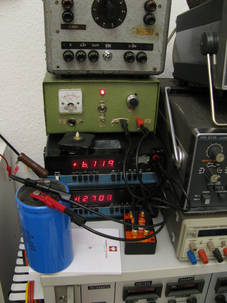
At 6.1V, I left it charging for about 10min. MAKE SURE TO NOT OVERLOAD THE UCURRENT SHUNT RESISTORS. The charge current settled at 1.27 uA.
According to the following chart, this seems reasonable:

Image Source: https://en.wikipedia.org/wiki/File:Leakage_current_behaviour.png
This project is not dead, yet ;) In the meantime, I've built an ne555 monoflop circuit and hooked it up to the clock. It works, but draws too much current. Maybe I'll go the JK-flipflop-route...
the clockwork consists of the drive (coil and small gear with attached magnet on the right) and the clockwork itself on the left:
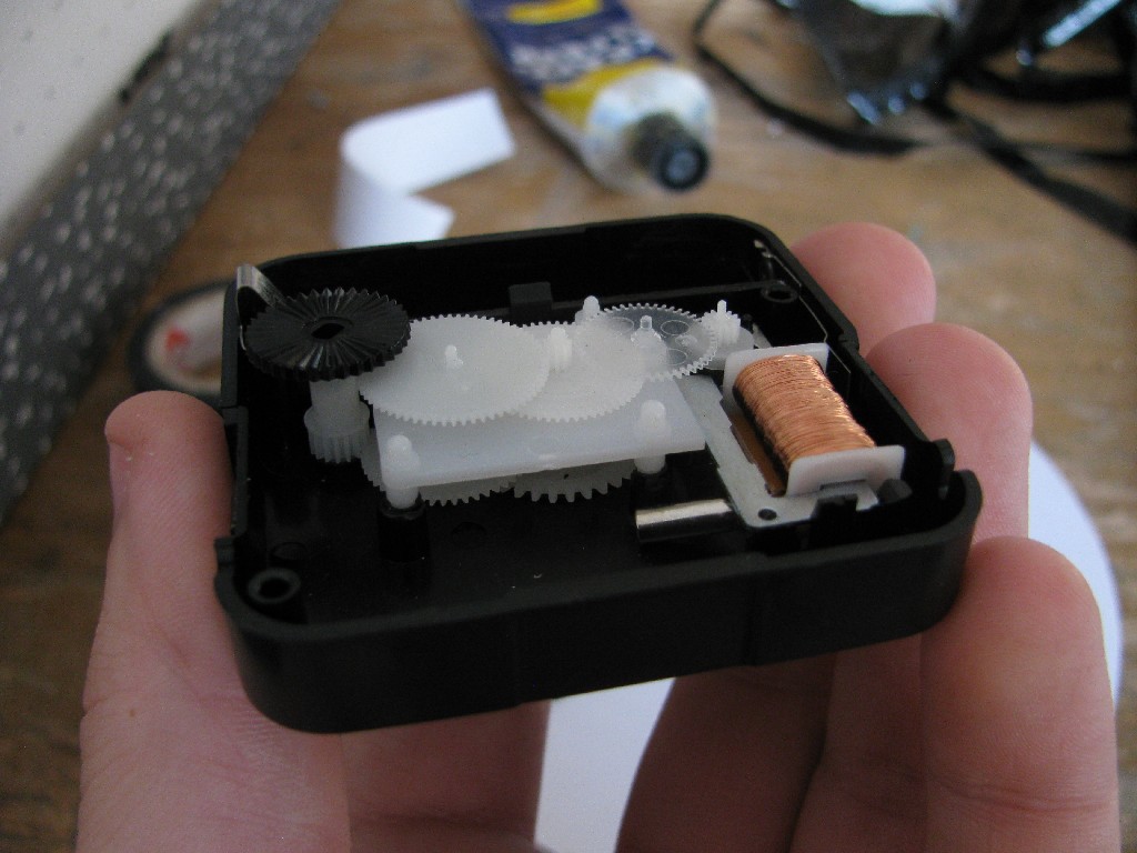
The three main gears are connected with two additional gears. Divider factor is "60" for each step, resulting in seconds, minutes (runs at 1/60 speed of the seconds pointer) and hours (runs at 1/60 speed of the minutes pointer):

the drive mechanism is really simple: 32kHz quartz, electromagnet, "logic" blob:
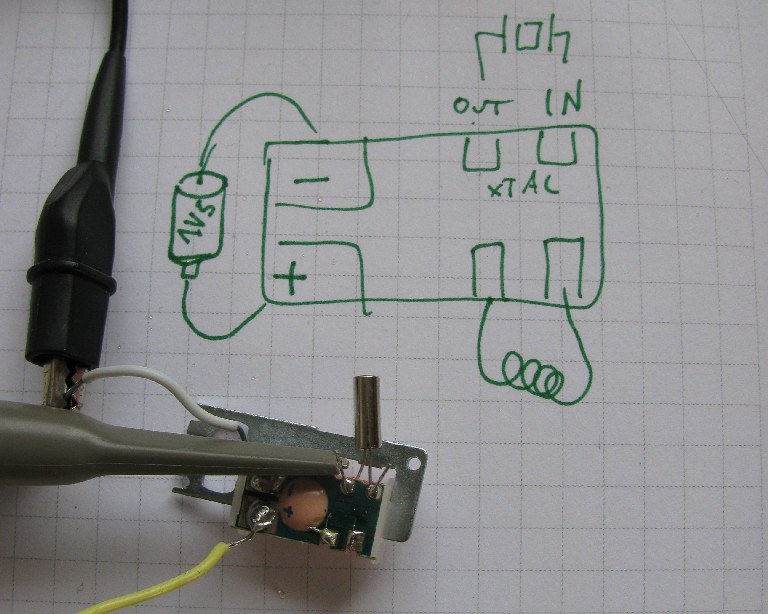
Which of the quartz pins is XTAL in and out can be figured out by probing with an oscilloscope: The pin with strong signal is XTAL out, the other one with a weak (or no signal) is XTAL in (input impedance of scope stops the oscillator).
Test driving the circuit with a function generator works best with AC coupled clock signal (there is already an internal resistor which drags the input to threshold between hi/lo logic levels:

With a bit of modification...
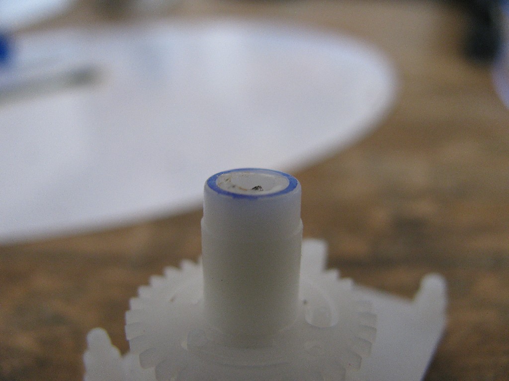
...and glue, the "world" fits on the hours pointer:
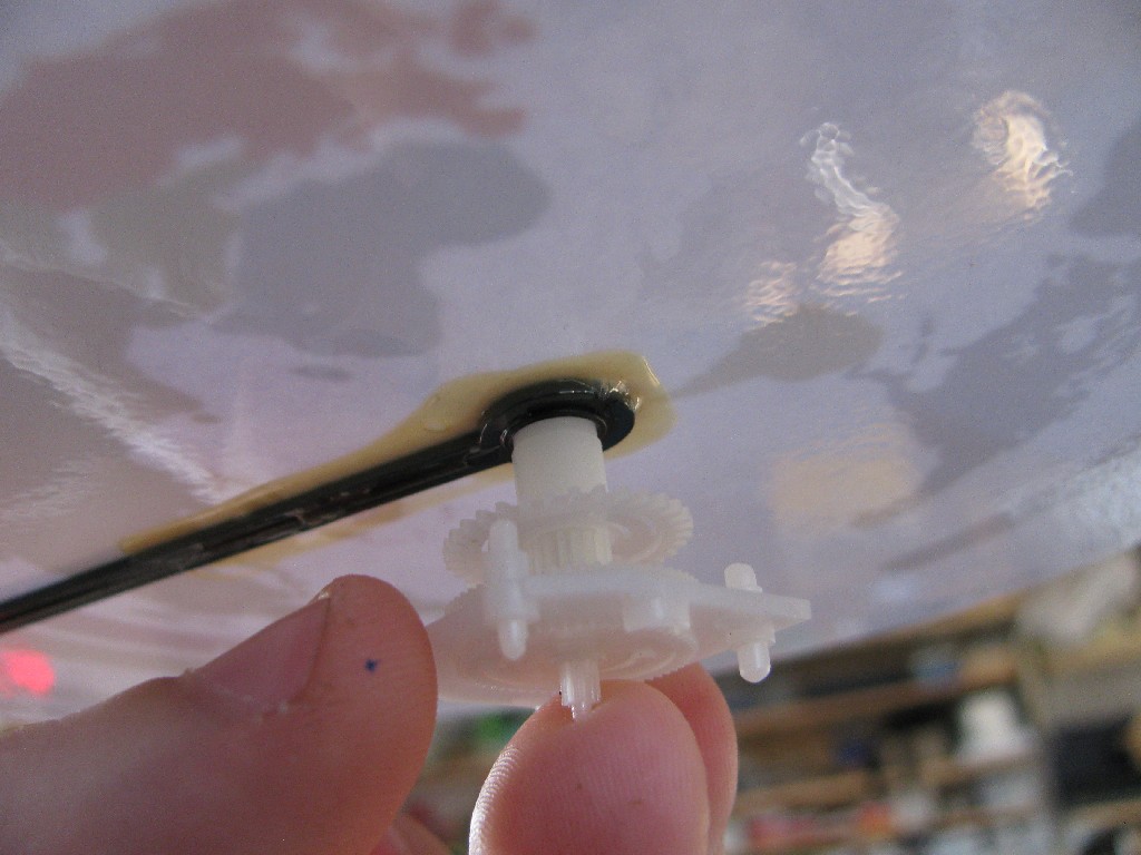
*tadaa*:
Around the world, around the world
Around the world, around the world
Around the world, around the world
Around the world, around the world
(daft punk)
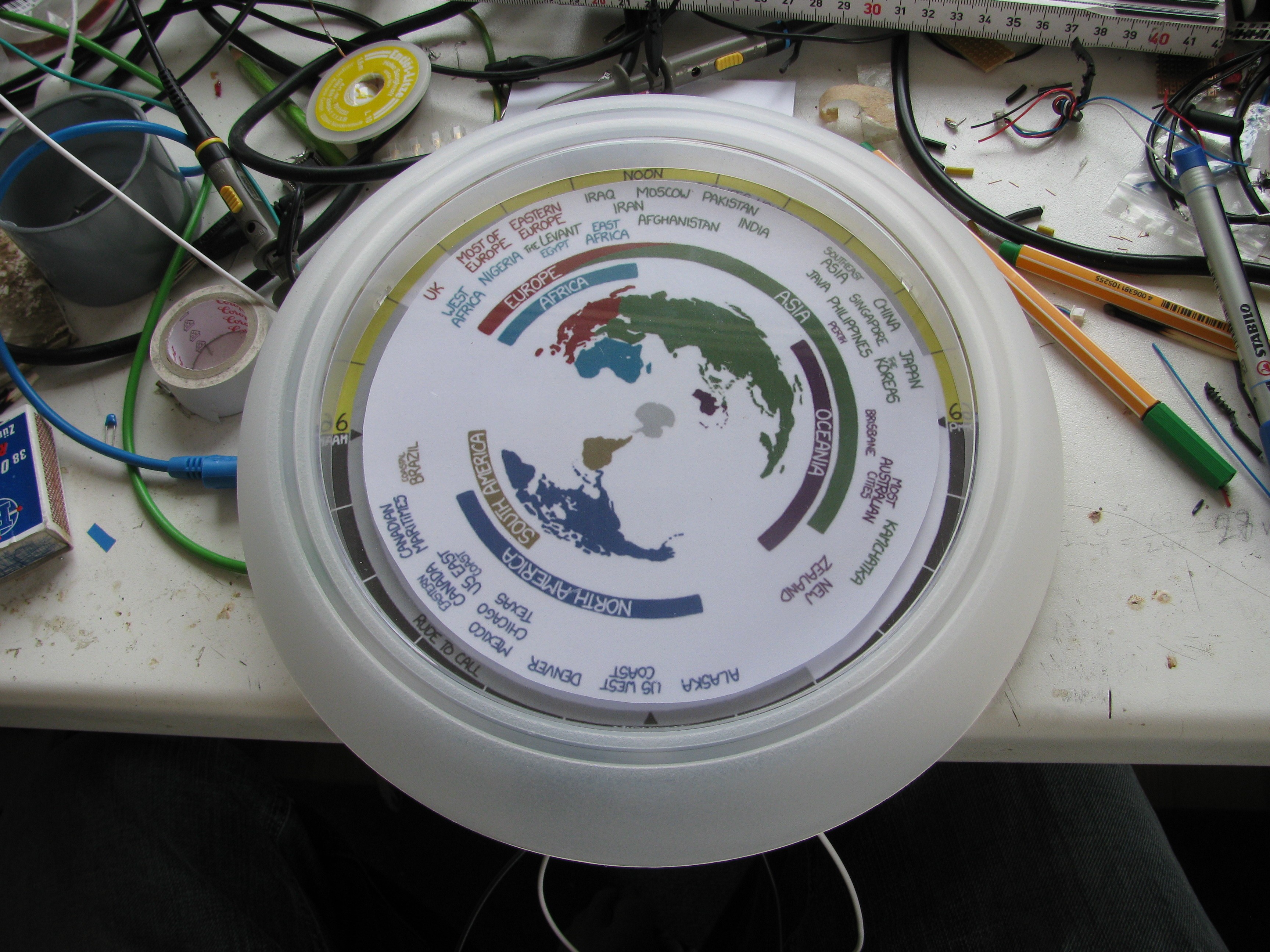
I'll leave it like this for now, maybe the outer ring will go on the white plastic frame later. It is possible to use standard acrylic paint for this (tested on another RUSH clock):
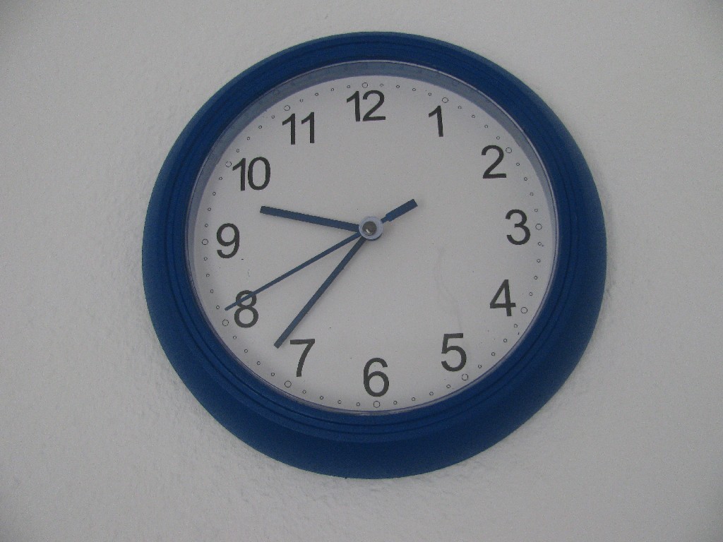
This clock stuff is a perfect excuse to upgrade my test gear and order an EEVBlog µCurrent GOLD, lets see how long the shipping to Germany takes...
today my chaos-driven round robin scheduler gave some processing time to this project - yay!
Printed, laminated and cut out with standard office tools:
..."assembled":
First I tought about drawing the outer ring (time + business hours / rude to call ring) on the clock frame, but decided against it to stay with the original look&feel as much as possible (= make the whole thing look "Commercial off-the-shelf").
---
Other Ikea clock mods I found in the meantime:
http://www.awikiventure.org/ikeaclock/
http://arduinoforgoodnotevil.blogspot.de/2012/05/ikea-clock-hack.html
http://kitschturd.blogspot.de/2011/07/mimis-clock.html
http://fastlaneillustration.deviantart.com/art/Who-Said-Ikea-Clocks-Had-To-Look-Like-Crap-288642020
http://www.ikeahackers.net/2012/11/circuit-clock.html
32768Hz oscilator works now 1-1.5V. I thought about further optimizing the design to only use one hex inverter IC and found the "wenzel clock divider http://www.techlib.com/files/dividers.pdf which I really like, but I was unable to get it running reliably for varying supply voltage to provide constant divider factor of two...
The oscillator consumes 2-3 uA (2uA for 1V, 3uA for 1.5V). This is relatively easy to measure with a multimeter in DC mode, as the current is nearly constant (the decoupling cap makes it possible).
How much does the clock run shorter with the added circuitcy on one battery?
There is a table of AA battery characteristics: http://www.powerstream.com/AA-tests.htm
As a rough estimation: 1Ah / 3uA = ~38 Years.
To measure the power consumption of a clock, just with a multimeter, is not as easy, because it draws pulse currents into an inductive load (which depends on the position of the constant magnet??). Calculation would base on a lot of assumption, measurement setup would involve a shunt resistor and scope, which I don't have handy right now - too much effort for an estimation.
As I have to replace my clocks batteries approx. every ~3 years (26280 hrs) , this means an avg. current of 38uA. With 41uA, run time would be 2,78 years instead of 3, = 7% / 80 days less.
Clock power consumption measurement to follow...
Create an account to leave a comment. Already have an account? Log In.
Become a member to follow this project and never miss any updates
 K.C. Lee
 alcor6502
 SwiftyTheFox001
 Gabor
Gabor
"If you get caught speeding on the way to a customs office, this costs an additional fee..." HAH!