-
Isolation-Routing?
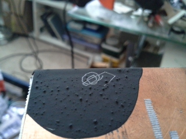
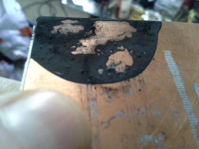
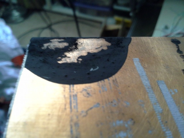
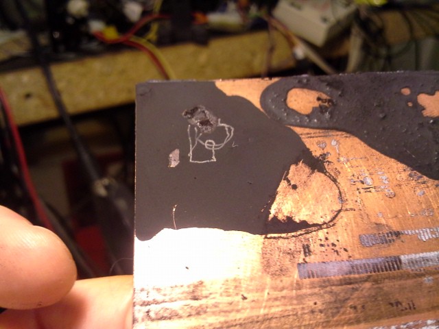
08/01/2016 at 11:06 • 0 commentsStrange accident resulted in the idea that maybe there's another way to do this... what about isolation-routing, instead?
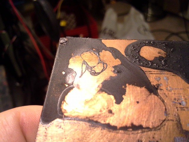
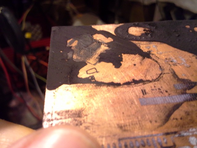
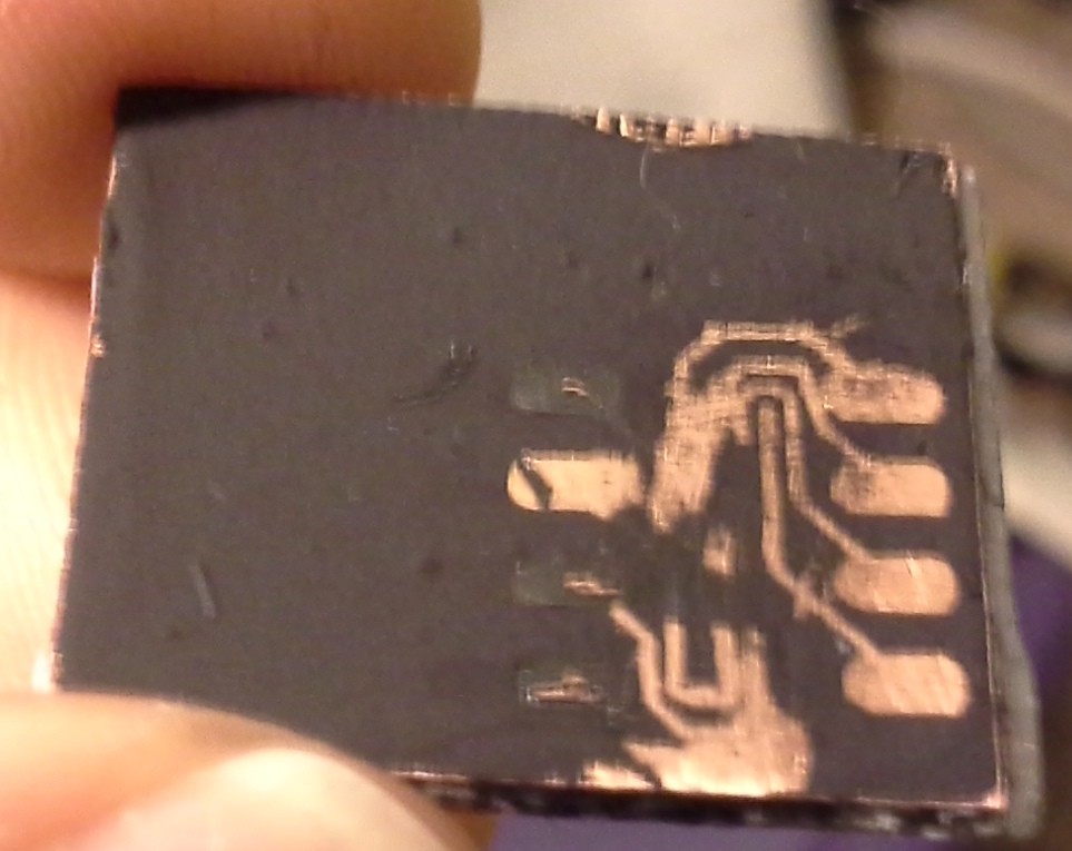
My results, so far, have been that wiping up the excess (unmelted) toner takes a steady-hand and a lot of patience... Makes one feel a bit like an archaeologist looking for fossils. Maybe I haven't got the slurry-density and feed-rates quite figured out... But I did a *really light pass* with the laser in one experiment, and it resulted in "traces" that melted together, but not to the copper... so they wiped away really easily, leaving the unmelted-toner behind:
![]()
So, instead, maybe do isolation-routing, where the traces will be the portions that *aren't* lasered, the unmelted toner that would later be adhered to the copper in an oven... Hmmm... I don't think many PCB-mills can isolation-route TSSOPs, right? That'd be a teeny-tiny cutting-bit!
More ramblings over at: https://hackaday.io/project/7535-cddvd-mechanisms-and-cartesian-thinggies/log/42926-first-cnced-toner-experiments
-
esot.eric overthought it again + grbl abstracted + first G-coding
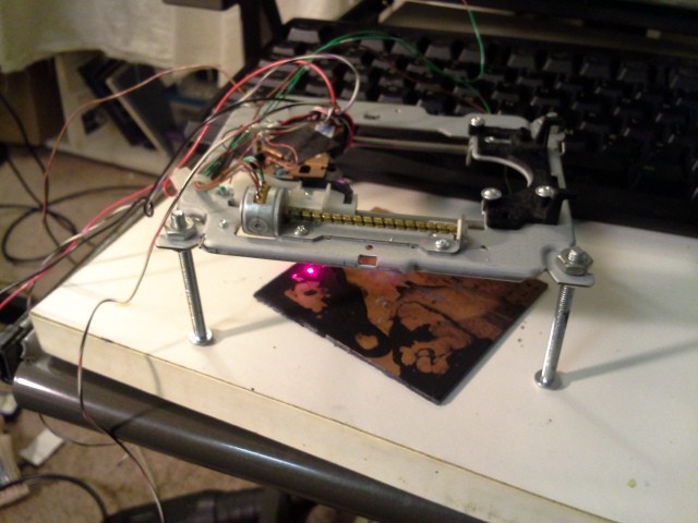
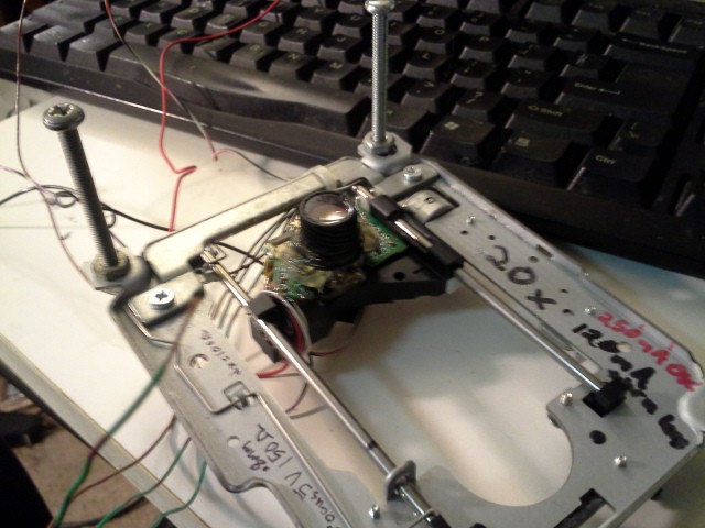
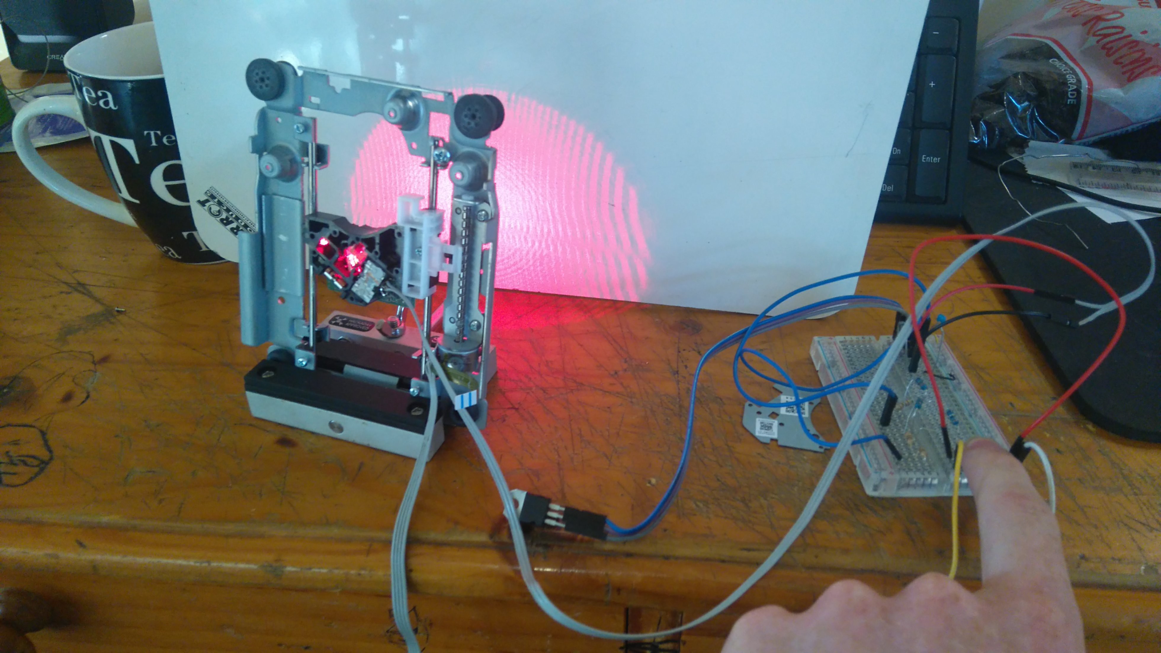
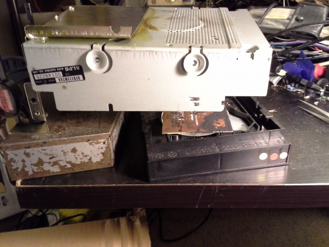
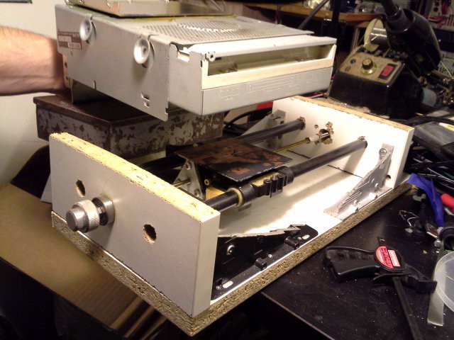
07/16/2016 at 10:13 • 1 commentAlright, so, those last two logs might've been just a wee bit overthought. Here's the new setup:
![]()
![]()
I dunno how I didn't see it before, DVD drives come in nice boxes with darn-near perfectly-square sides. Gravity can be your friend, too! Remove that focusing-lens altogether, and the focal-length is darn-near perfect.
Also: weeks of hard work, and grbl 0.9j now runs on PIC32, and more, including: it has been abstracted for porting to other architectures with relative ease, and now can directly-drive H-bridge inputs (rather'n step/dir) with single-stepping or PWM-micro-stepping.
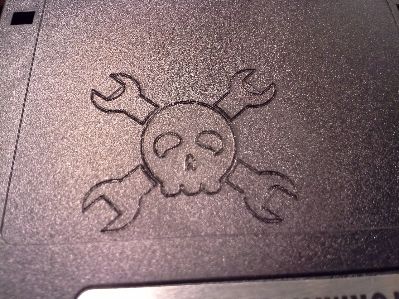
With 16x microstepping, the HaD logo takes just about 1 minute to etch.
Next steps: design a mini PCB, laser-toner, etch!
-
esot.eric's random over-thinking on zeroing
06/01/2016 at 02:49 • 0 commentsContemplating my first PCB to be made on this device, which will most-likely be the actual controller *for* my mini-pcb-printer. (Whereas for the first-runs, it'll be done on breadboard). The thought occurred to me, I'll most-likely need double-sided in order to fit two motor-driver-chips and my uC. But how to align those sides...? And some other overthinking on alignment.
Heads-up, this is overthinking, sometimes that's a problem... And, for non-dense and/or one-sided designs this is *most definitely* unnecessary overthinking.
So the quick-thought is this: Drill two holes in the PCB near opposite corners. That's the "easy" part, right? Next, install on the "bed" two pins aligned for just that. That alone might be enough, but another thought is:
a) skew (maybe my two axes aren't perfectly parallel, but good 'nough that say a TQFP could be soldered-up... That'd work fine for one side, but what about alignment on the other, wouldn't the trapezoids align such that their sharper corners are askew to each other?
b) zeroing the axis repeatably (on either side) might be a bit difficult
Now, if we can get *rounded*-head pins (or maybe even flat-headed?), surely they exist, with a slight taper such that they center themselves on the PCB-holes...
Now, I'm already reusing the DVD-drive's optics, which not only include a laser, but *also* photo-diodes... And our PCB material is coated in black toner... so the pins themselves would be a very bright reflection of the laser-beam.
So, darned-near perfect alignment could plausibly be achieved by manually moving the laser-head/bed *near* the pin-head, and a short "search" algorithm for that reflection. Do this twice, once at each pin, and we can also determine (and automatically-subtract) [small] potential-skew between the two axes.
Again, it's probably overkill.
A few other-such-overthoughts:
Design a "part" in the PCB-layout software to auto-place these holes (and avoid placing other parts in that area, or even plan to use them as vias).
These holes needn't (maybe *shouldn't*) be at the far-extremes of the axes' motion.
These alignment-guides could auto-calibrate the system for inches-to-stepper-steps. (On my system, the two axes are clearly different thread-counts-per-inch)...
A jig could easily be made for the actual drilling of these holes; drill one first, place that hole on a pin on the jig, Bam.
Another(?) jig could easily be made for alignment for drilling the other vias/holes.
Inserting the pins into the "base"/"bed": Currently my "bed" is nothing but a sheet of acryllic... Drill holes in some (single-sided) PCB-material (maybe multiple layers simultaneously, for stability and verticality). Rest pins and PCB-jig(s) atop the base. Heat Pins Hot. (Soldering-iron, heat-gun? PCB-jig(s) acting as a heat-shield?) Press down into base.
(Better to use thin "pins" e.g. sewing-needles, or wider ones such as docking-station alignment-guides? Latter is more likely to have a large enough surface for reflection...)
Sharper-pins = easier "post-it-note focussing"?
(brightness ==> focus?)
(will two pins actually be enough to determine skew when axes' steps-per-inch are unknown?! Hmmm)
Again, it's probably overkill.
-
esot.eric's upper axis
05/30/2016 at 12:45 • 2 commentsHello! It's been a minute...
So here's where I (@esot.eric) am at with the ol' #Mini PCB printer
![]()
Click that "Read-More" link, below!
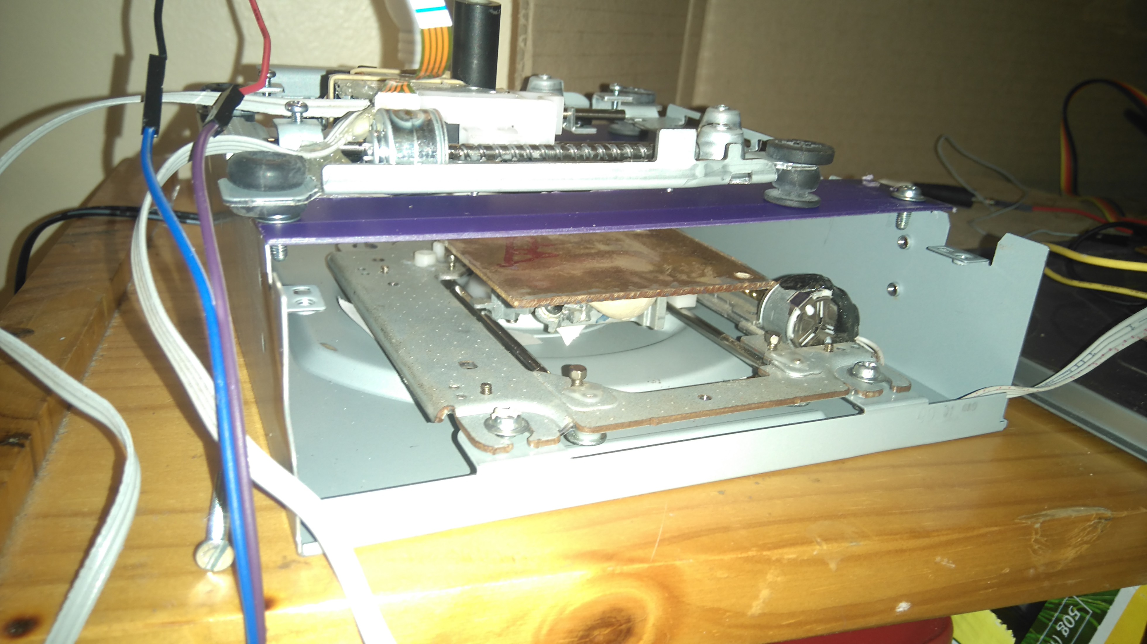
I decided to go a slightly different route than the whole "mini" part. For my purposes, that means the upper-axis (containing the laser/optics) is going to be its own module, separate from the bottom axis (which moves the PCB material. That way I can attach the upper/laser axis to a larger lower-axis when necessary.
![]()
![]() And here's the laser-lens and slide-mechanism:
And here's the laser-lens and slide-mechanism:
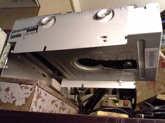
I managed to keep the DVD sled in the drive's housing, attached the lens to the drive-sled, and cut a slot out of the drive's housing for the lens to move in. (Handy that the spindle was such that there was already a big ol' hole in the top of the drive!)![]()
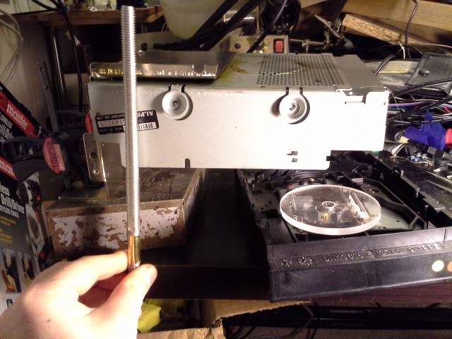
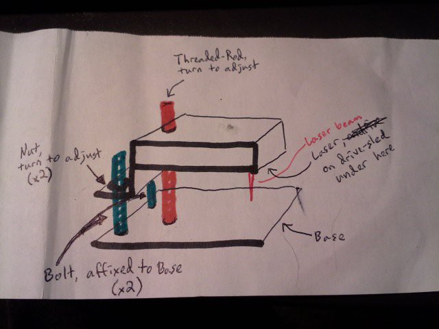
The DVD drive's housing is mounted in, believe it or not, the metal frame from an old Apple IIe's 5.25in floppy-drive, this guy got "welded" (poorly) to a bracket shaped a bit like a Z. The concept is shown below. The idea being that adjusting two nuts and a threaded-rod should allow for not only height-adjustment for different lower-axes, but also fine-adjust for focusing the laser. Though, as @johnowhitaker has pointed out, it's much easier to just adjust the focus once a little bit higher than the bed, then use something like post-it-notes to adjust the height of the PCB into focus. So, I'll probably end up doing that most of the time.
I guess there's no real necessity for the Z-bracket attaching to the blue bolts, except that I didn't have really long bolts, I needed a little bit more distance out the back, and I wanted to try my hand at some stove-top solder/welding. So, I "welded" that bracket to the drive-frame by applying flux to both pieces and setting a big ol stretch of solder between the two pieces of metal. The idea, then, was that it'd heat up on the stove long/hot enough to melt the solder between and squeeze it out the sides, bracket sinking comfortably into place. I think it might've worked quite nicely, but the smoke was pretty extreme (took most of the day to clear out of my apartment) and right toward the end the grease/carbonized food sitting in the stove-burner's "drip-pan" actually caught flame. So I aborted early and just kept it as-is. The "weld" is a bit wonky, not at all square, but still seems pretty sturdy. Again take a look:![]()
![]()
I hesitate to do this sort of work in the oven, as I don't want lead/flux fumes lining the thing. And I didn't have a pan big enough to set this entire contraption in, so wound up setting the metal right on the burner with a sheet of aluminum-foil between. Probably not the wisest, as that foil trapped in the heat of the burner and I think that's why the grease below caught flame. Besides that, surprisingly(?) the aluminum-foil actually melted (or burned?) in a few places, and a little bit of solder did actually find its way onto my burner, though that scrubbed right off pretty easily.
Again, I think it could've worked well with better airflow and a better pan... (don't leave it unattended, and don't forget that baking-soda nearby!).
My lower-axis DVD mechanism was a bit of a stupid mistake, on my part. I had the actual sled-mechanism outside the drive's housing for a while and got it all prepped before realizing that it was originally mounted in the drive's housing at an angle. So much for using the housing as a "square" (though, I suppose, the upper-axis is probably a bit off-square with my "welding" technique, as well).
The "Bed" for the PCB (etc.) material is nothing more than a piece of acrylic that'd been cut out with a hole-saw... was just sitting around and happened to be darn-near the perfect size and had a perfect sized hole right in the middle to be screwed down to the laser-sled.
![]()
Hah, weirdly... I've been putting off attaching the bolts and threaded-rod to a base for a while, now... Not really sure how sturdy they'd be. So for setting up the system for these photos I just grabbed some things to set it on (that's a box of drill-bits) and clamped it down to the table... And, it took me until proof-reading this post to realize: "Wait a minute! I could just clamp that thing down *just like that* to use it!" Been a bit slow, lately, I guess. Maybe I'll switch over to electronics/software now that I've got my mechanics figured out :)
-
Summary for round one, THP 2016
04/22/2016 at 19:26 • 1 commentHere's a summary of the project so far, to save you judges (and anyone else interested) from having to dig through all the old logs just to get an idea of what this project is about. Here goes:
The goal was to make a small laser engraver, and figure out a way to use it for making PCBs. After trying to cut away tape, or use a permanent marker to outline traces, we came up with a rather novel way of doing it.
A 'toner paint' is made by mixing toner powder from a laser printer with alcohol. A copper clad board is coated with a layer of this toner slurry. A laser attached to the XY system is used to selectively melt the toner in the desired pattern. The un-melted toner is removed, leaving a nice etch resist.
I burnt out my laser(s) messing around, and deleted some photos of the latest progress (!!). Nonetheless, the basic idea is sound, and the technique does work. However, I am interested to see how far it can go. The next logical step is to use melted toner as a silkscreen as well, but beyond that I'd like to try a technique similar to the light-scribe method for making capacitors. Except that by adding alternating layers of toner (as dielectric) and graphene we could potentially get caps with more surface area (and thus greater capacity). All that will have to wait until I can scavenge a new laser or buy one with the seed money :)
For those wanting step by step instructions, a good set to follow are those by groover on instructables - http://www.instructables.com/id/Pocket-laser-engraver/. His design is very similar to the one I ended up with. Or, search for microslice as they too have a good breakdown of the software and hardware parts of a build like this.
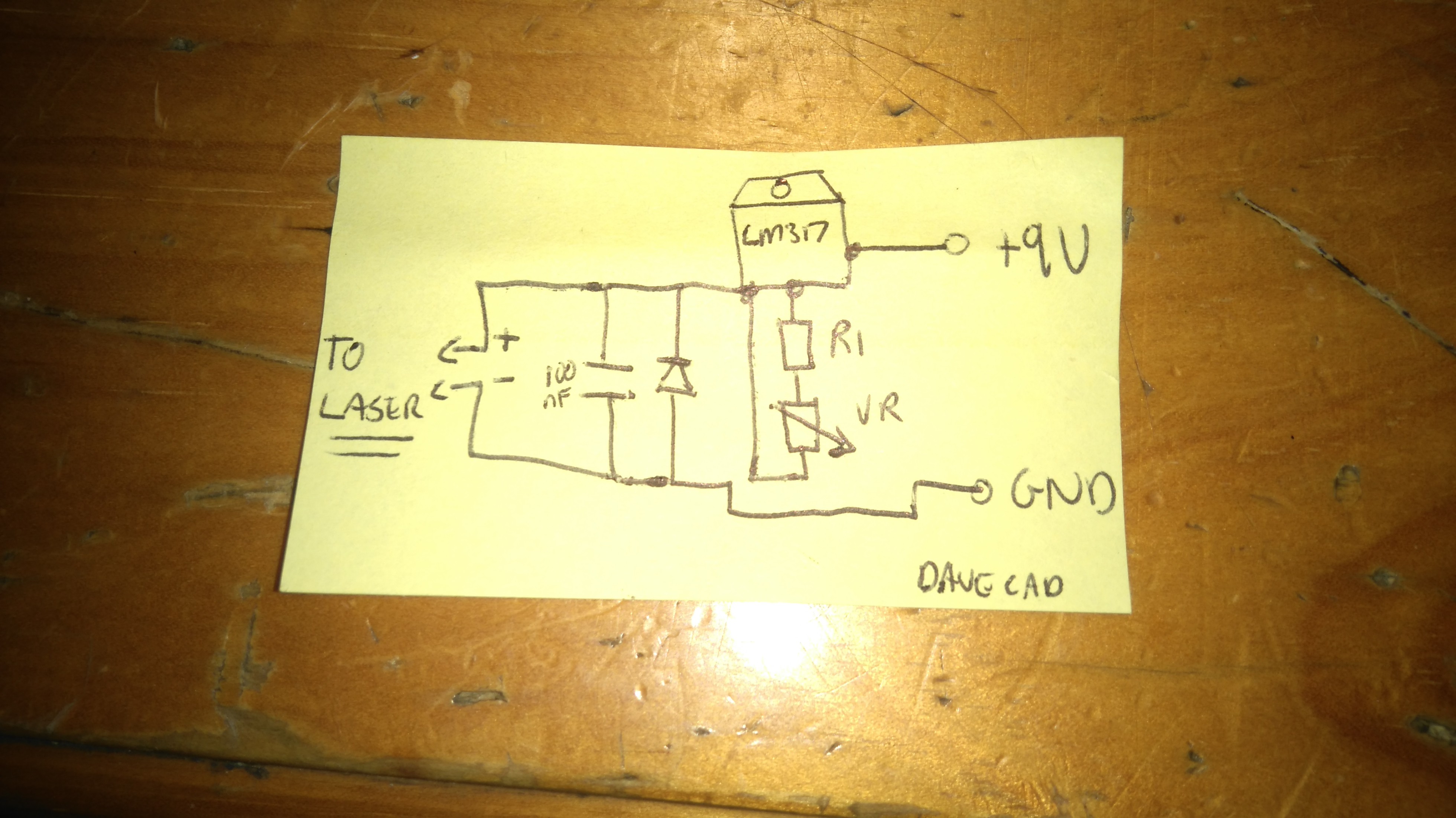
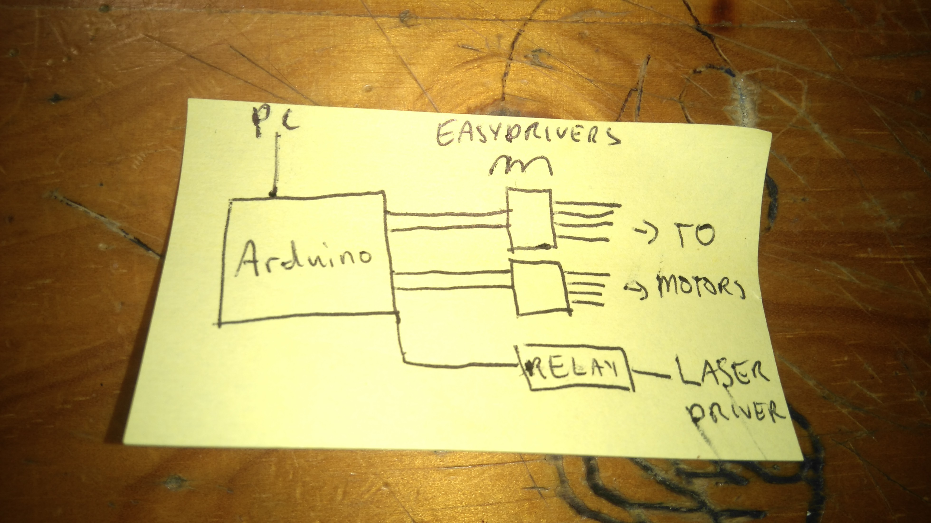
The laser driver I use follows the instructions at http://www.langeder.org/homemade-laser-driver-with-lm317/, with a few modifications. I did at one stage use a mosfet to switch the laser, on and off but switched to a relay for the latest build because it was easier, plus the click and glowing light on the relay module are useful for debugging. I also modified the inkscape extension from the microslice guys, so that it now uses M4 to turn the laser on and M3 to turn it off. Those commands toggle an LED on pin 13 in the default GBRL setup, and it is trivial to wire up pin 13 to the relay module as well.
In the above schematic, I have three 2 ohm resistors in series as R1, and a variable resistor to fine-tune the current.Also, between the 9V supply and the laser driver is the relay module, so that it only has power when the arduino writes pin 13 HIGH. Here's a block diagram:
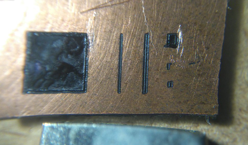
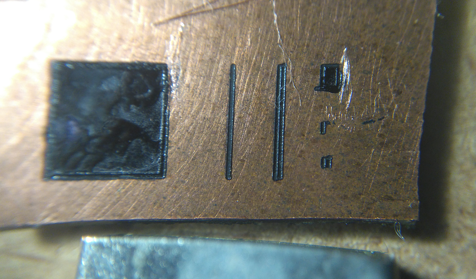
What makes you think this project log was written soon before the deadline? Here's a final shot of the best results so far, showing everything from a 5mm by 5mm square (top left) down to a .5mm square bottom right. Thinnest trace is about 0.25mm - a bit wide, but workable. There is a USB plug in the bottom of the photo for scale.![]() I really think this technique has promise, and I hope I can take it further over the course of this contest.
I really think this technique has promise, and I hope I can take it further over the course of this contest. One final note: I (Jonathan Whitaker) focused on my system in this log, but my team-mate @esot.eric is replicating this system as well. He has been able to melt some toner manually, and I look forward to his results once he gets his XY system going. His #CD/DVD mechanisms and cartesian thinggie[s?] project and comments on my old #Mini Laser Cutter persuaded me to dig out my old project and try this. That's the power of a community like hackaday.io :)
-
Better test-bed my side
04/06/2016 at 21:48 • 0 commentsJust a quick update - mainly photos of progress.
![]()
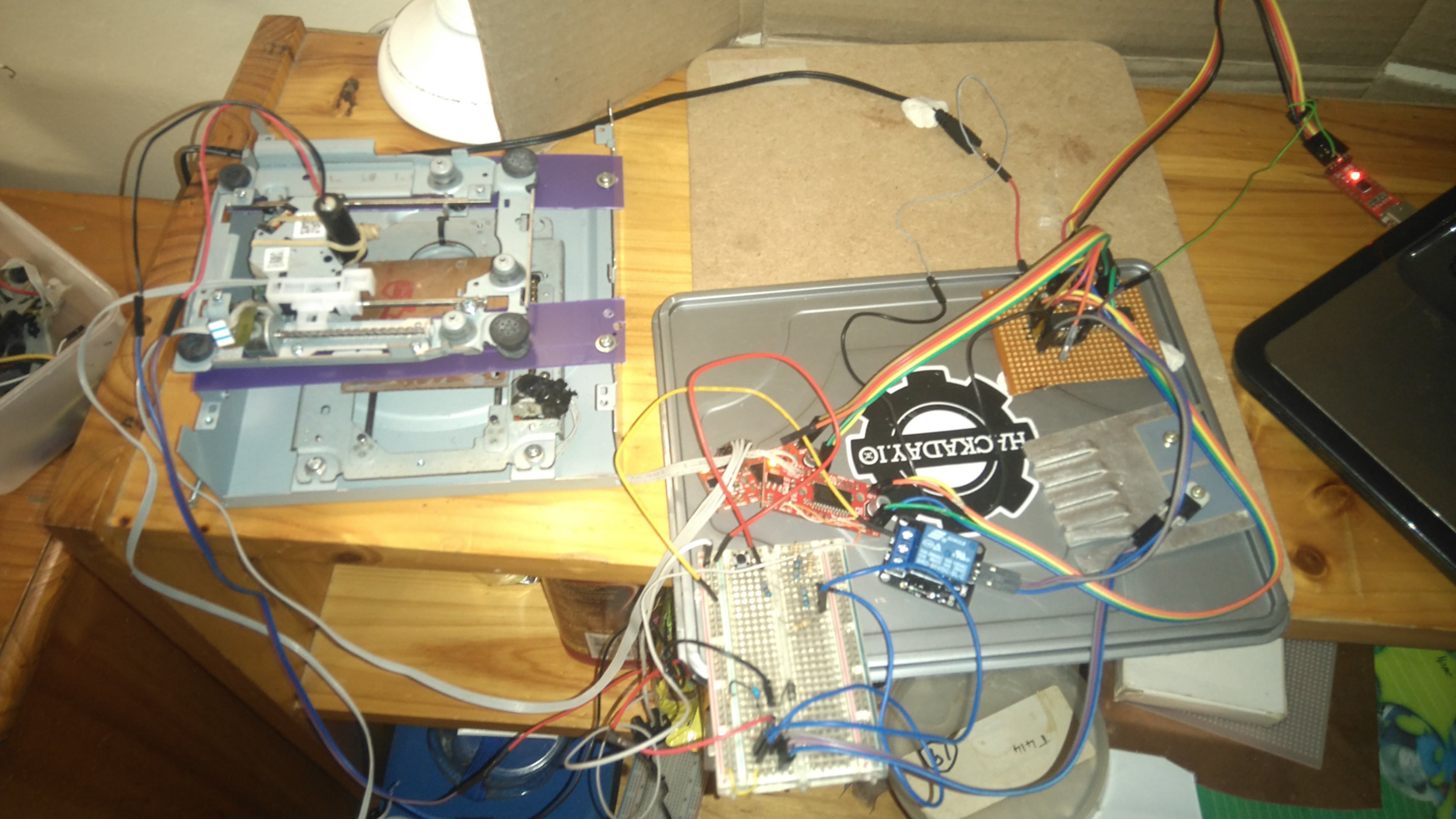
I made a proper frame to keep the axes perpendicular, and control the height of the laser. I'm currently using an IR laser I bought, with adjustable focus. The laser driver circuit is controlled by a relay module (I was in a hurry), and the rest of the system is still the same - two easydrivers and a bare-bones arduino with GBRL. The test pattern below is the first usable output!
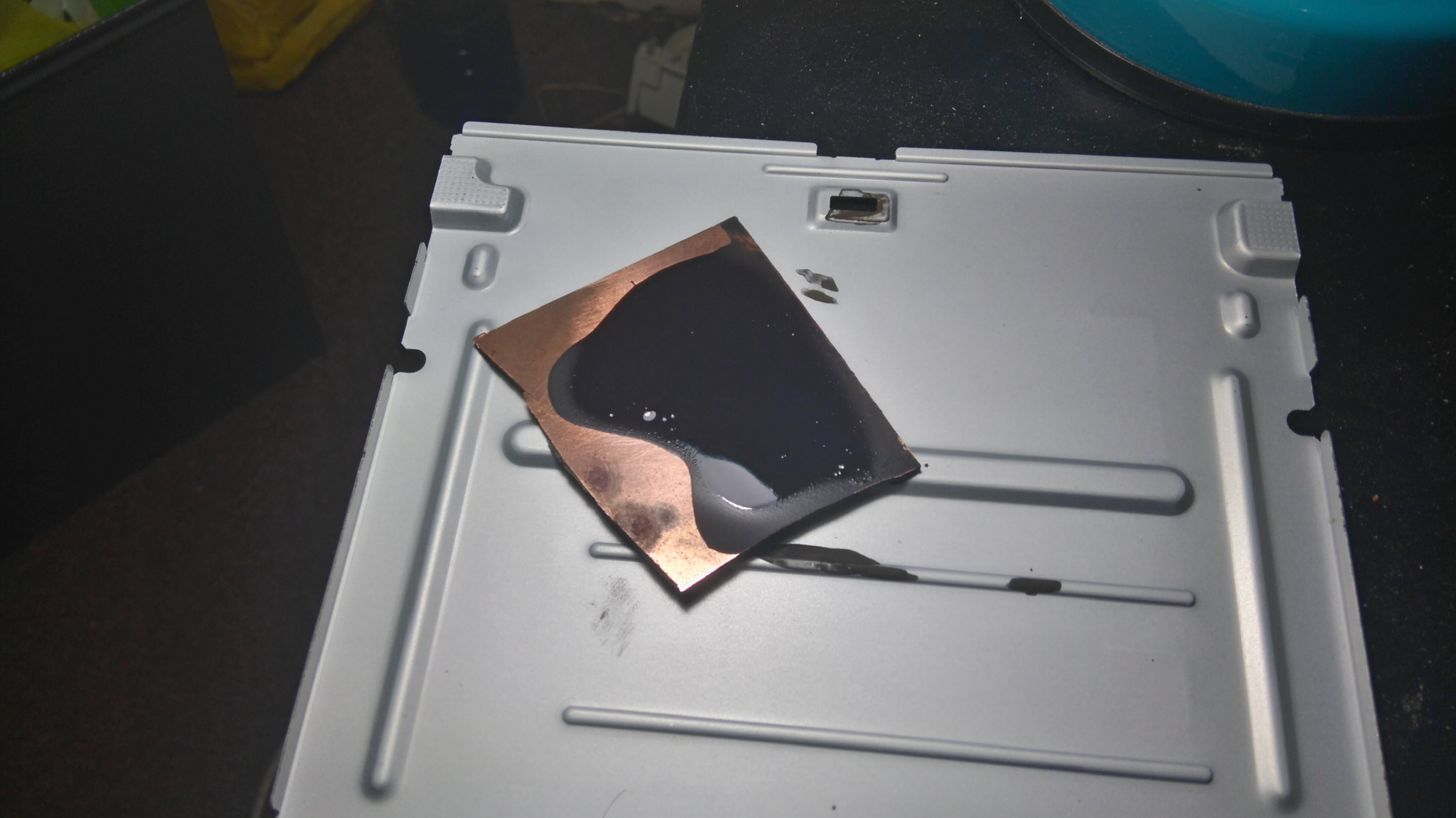
It took some trial and error to get the traces durable - the first few tries brushed off too easily. The trick was getting a thin regular coating of toner (very runny slurry of toner in alcohol - it should dry in a few minutes) and making sure the laser was focused properly.
![]()
Here's the board being prepared:
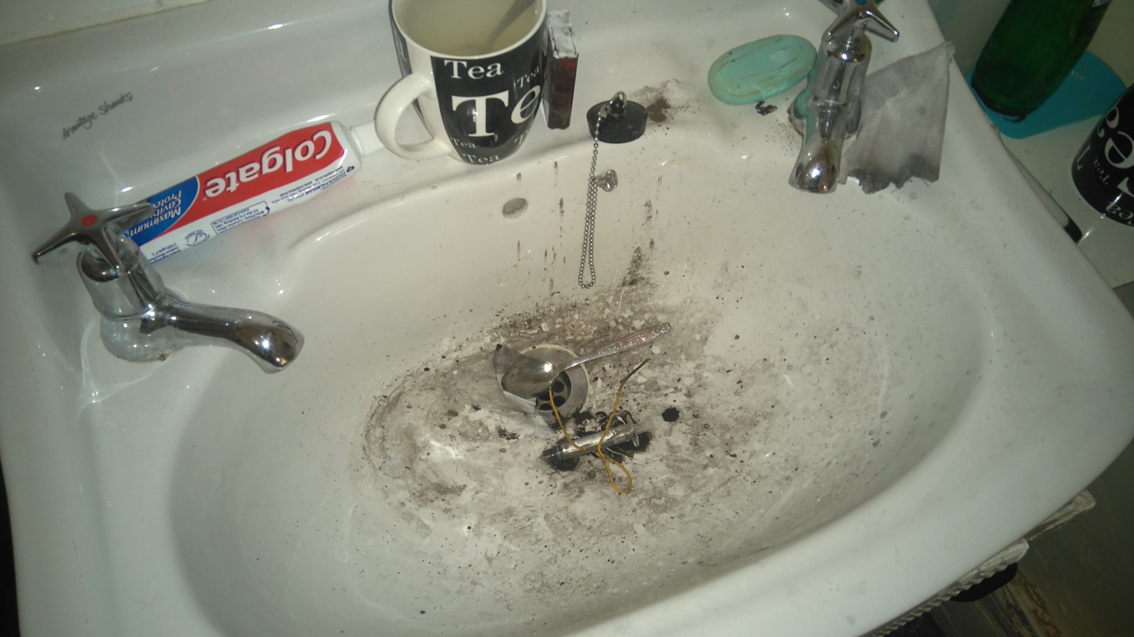
and the sink after a few spills and some silly mistakes:![]()
NB: There are some health concerns about the toner powder. Please clean it before it dries and try not to breathe it in. It is just plastic, but because it's very fine particles it can be problematic.![]()
Another shot of the XY part of the system:
The pic of the test pattern is taken using a DVD drive lens on my phone. The silver thing is a USB plug, and the boxes are (left to right) 5mm by 5mm, 5x0.3, 5x0.5, 1x1, 0.5x0.2 and 0.5x0.5. I filled the two largest using a permanent marker, and went a bit over the lines. Also, there are little 'serifs' due to lag with the laser switching system. I can't actually etch the test pattern until I get my hands on some vinegar, but I washed and rubbed the board quite vigorously and the traces held up, so I know from previous experience that there shouldn't be any trouble etching it.Next steps: Tidy up the drive electronics into a box (with a fan), etch an actual board, make a decent video and figure out how to get a consistent coating (maybe a spin coater).
-
esot.eric's first attempt at johnowhitaker's Toner-Lasering Technique... GO!
04/06/2016 at 08:56 • 0 commentsIf you haven't seen it already, over at #CD/DVD mechanisms and cartesian thinggie[s?] @johnowhitaker came up with a technique to laser-melt toner directly onto materials such as copper-clad board!
(That description and link will likely become a bit redundant, as this project-page progresses!)
Here's a log of my (@esot.eric) attempts. Result: VERY PROMISING.
See More about my experiments... Click below!
This is from a 20x DVD-RW drive. The focusing-lens has been removed and this lens hotglued on. This lens is from an old camera, but its focal-length is about the same as a magnifying-glass. In fact, I used a magnifying-glass for my earlier experiments and only decided to use this one because its size lends itself well to mounting. (In other words, if you've got a magnifying-glass, go ahead and use it!). The result is that the focal-point is an inch or so away from the laser (rather than the original focusing-lens's 1-2mm) making it much easier to focus on the material (in fact, it seems to work fine without adjustment for materials as thin as tissue-paper to as thick as a PCB).
This particular laser I've been running at 250mA reliably. I haven't attempted to go higher. (And, for the above photo, I accidentally wired it backwards. Thank Goodness it didn't blow! My supplies've run out and my graveyard is large!)
-----------------
These attempts are all moved by hand... Now that I've got these VERY PROMISING results, I'm going to rig up an X-Y system soon.
-----------------
Here's an early (failed) experiment.
Note that the laser's path is clearly visible (nice!).Note also: Do Not Shake the mixture! Stir it carefully so as not to introduce air-bubbles!
@johnowhitaker's formula is: Rubbing Alcohol and Toner. It took a few tries to get the right thickness (and, actually, I'd almost given up before finding it).
I used the butt-end of a pen cap, with a white/clear housing, to stir the mixture. First I poured toner into a margarine tub, then I added a little alcohol while the tub was tilted. The toner didn't mix in entirely, so I kept scooping more in until the thickness was *just enough* to coat the pen-cap (no more!) and still drain off slowly, revealing the color of the pen-cap.
At that point, pour it onto the PCB and drain it off...
Here's another from the first failed attempt(s):
I drew a "2" (sideways, near the bottom).The idea is to use a cotton-swab to remove the un-melted toner surrounding the lasered-portion. If the mixture is too thick, it seems to dry like thick paint, and the amount of rubbing necessary to remove it is enough to damage your traces. This one *seemed* to work, but wasn't quite right, and by the time I got it all cleaned up the traces were damaged... here's the lasered-portion for comparison:
Note how there was no lasered "cross-piece"... Frustration with trying to remove that and surrounding material ruined the traces.
Note: Don't rub vigorously with the cotton-swab, friction creates heat, heat melts toner.
(For size-comparison, the row of pads on the right are for a compact-flash connector, using the old toner-transfer-paper method, long ago).
Note also: Don't try using alcohol to clean up (until later)... it just rips the traces right up.
Now for the VERY PROMISING results:
This, again, was with it *just* thick enough to coat the pen-cap while still draining off slowly:
This is a little bit confusing, I didn't clean the board first, so there's a patch of permanent-marker near the corner interfering with the toner and traces... This was a handy unintentional experiment, too... I'll talk about that later.
I also added a square later-on... Here they are rubbed off with a cotton-swab (note the ugly permanent marker still under the first squiggles).
The traces actually have a bit of heft, almost like... the results of a layer from a 3D "cornstarch-printer" (whoa! hmmmm).
Now here's where that patch of permanent-marker gets interesting... Notice how clean the square turned out, with just some rubbing with a cotton-swab... Cool! It was pretty resilient this time. Awesome. Then I got a bit cocky and decided to try alcohol cleaning, and that square wiped right off.
After that I heated the "squiggled" area with a heat-gun to "set" the traces. Worked well... And then, I tried alcohol again... this time to clean up that permanent marker... and... NO PROBLEM.
Those traces are measuring about 17mils, which is a bit larger than I expected, but perty good for home-made early experiments, no?
I'm certain the laser could be better-focussed, also maybe the toner was still too thick, and flowed a bit when I heated it... I certainly wouldn't put the resolution cap at 17mil with this first experiment.
So, some observations... This turned out much better than I expected, especially after those initial failed attempts. I hesitated to rub too hard to clear out the unmelted material between corners and in tight spaces, but I think I could've been more vigorous (or at least more patient) and gotten even better results. Maybe a thinner mixture would work even better. And, one could design boards around these constraints, as well. (or might not even have to). I was thinking to try to avoid things like sharp corners, thinking about paths for material-removal... but then again, where there are sharp corners, there's probably not going to be *another* (unconnected) trace nearby, so even if the excess material isn't removed, it probably wouldn't matter.
And, besides, look again at that detail (WTF? My camera was set to 640x480?!)
Even in the sharp corners it cleaned up pretty good.Now, as far as resilience for PCB-etching, I think it's pretty much a sure thing. Awesome.
(I'll wait 'till I can actually etch a usable board before trying).
As far as using this method for e.g. creating labels on metal instrument-panels... I'm not sure yet. It can be scratched off, but I didn't try heating it more (and from the bottom?). Clear-coat over the top might be a good idea. Or maybe even a clear pre-treatment under the toner to make it grab better?
AGAIN:Keep following this project-page for updates and more-detailed instructions/experimental-results. Also, check out @johnowhitaker's original log-entry for step-by-step instructions and his #Mini Laser Cutter.
-
Starting out
04/06/2016 at 06:48 • 0 commentsMy #Mini Laser Cutter was disassembled and broken, so I'm starting again and focusing on the PCB fabrication aspect. To that end, I pulled the DVD drive from my PC (don't need a drive THAT much) and took it apart to see what I have to work with.
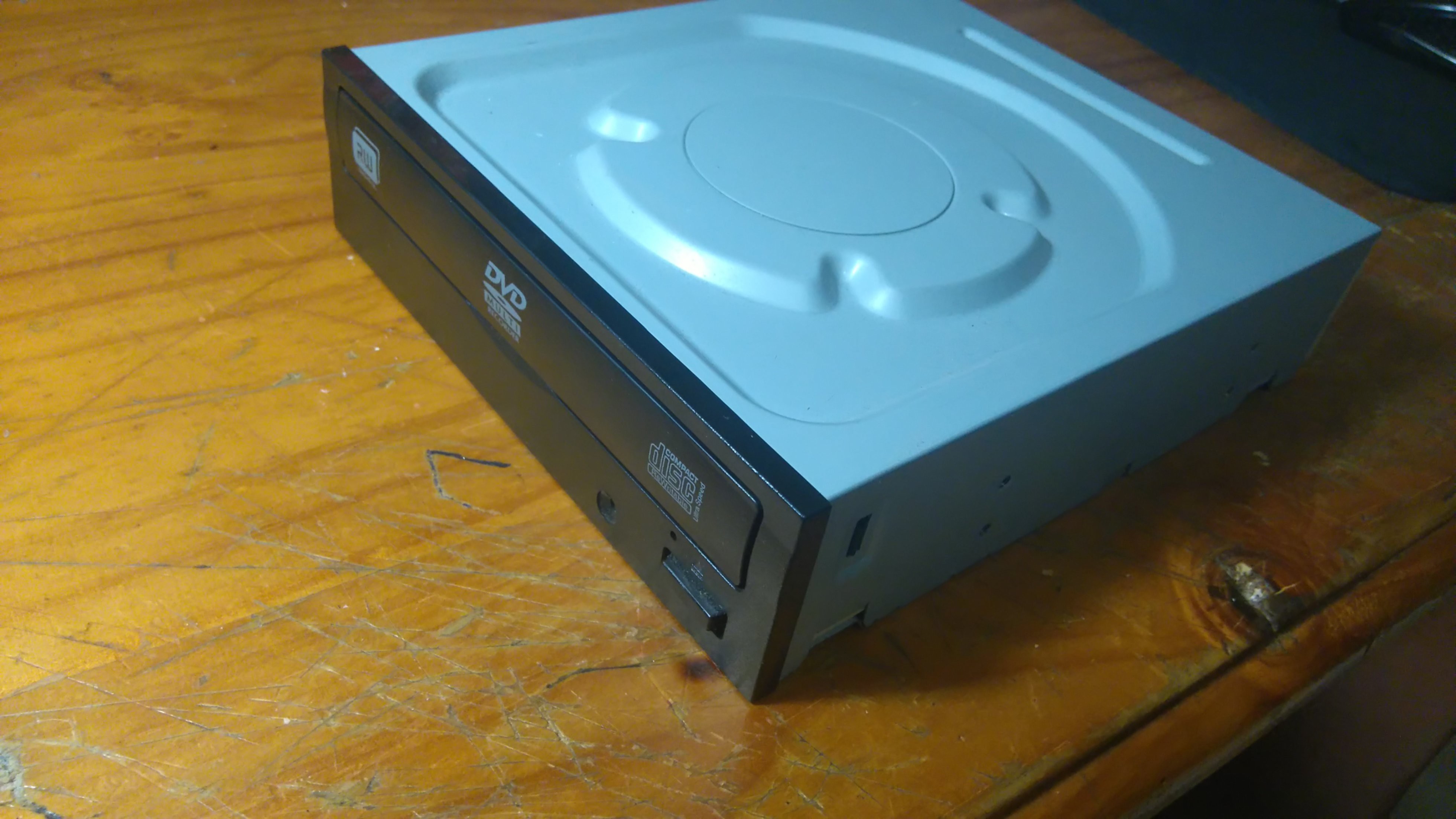
The drive:
![]()
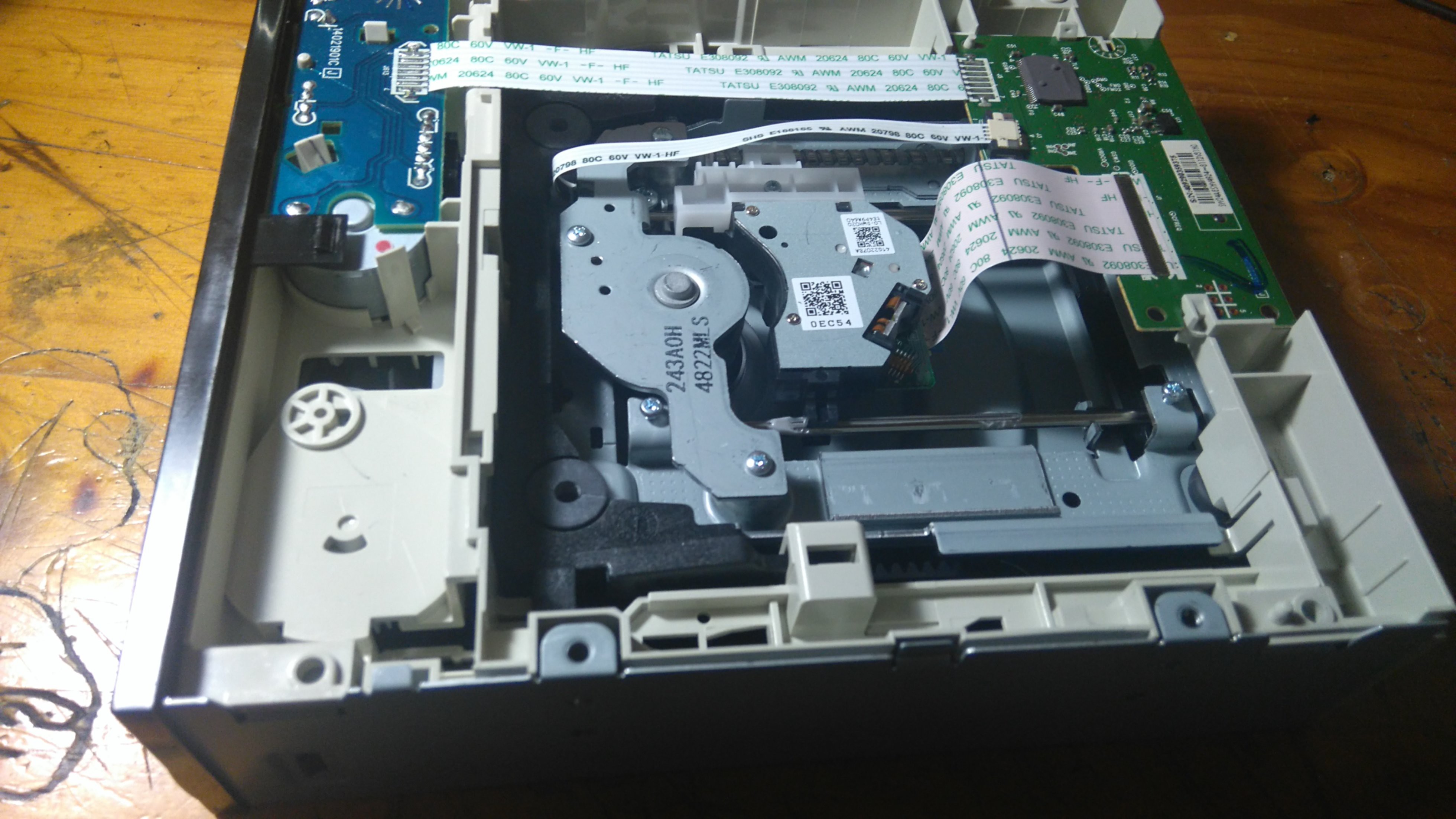
Removing two screws reveals the innards:
![]()
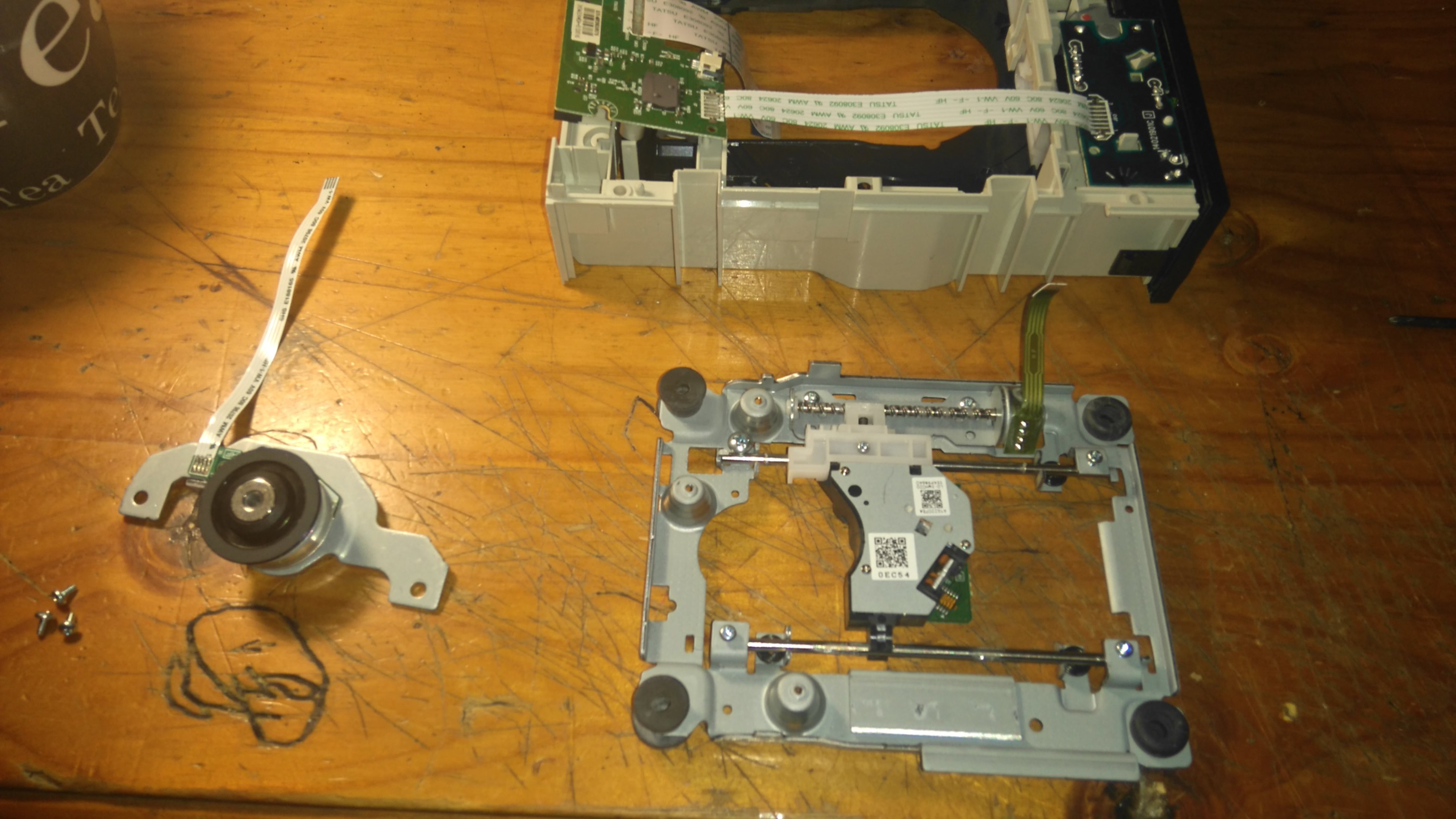
A few more and I have it in pieces - the eject mechanism and main board, the brush-less motor and the slide/pick-up mechanism:
![]()
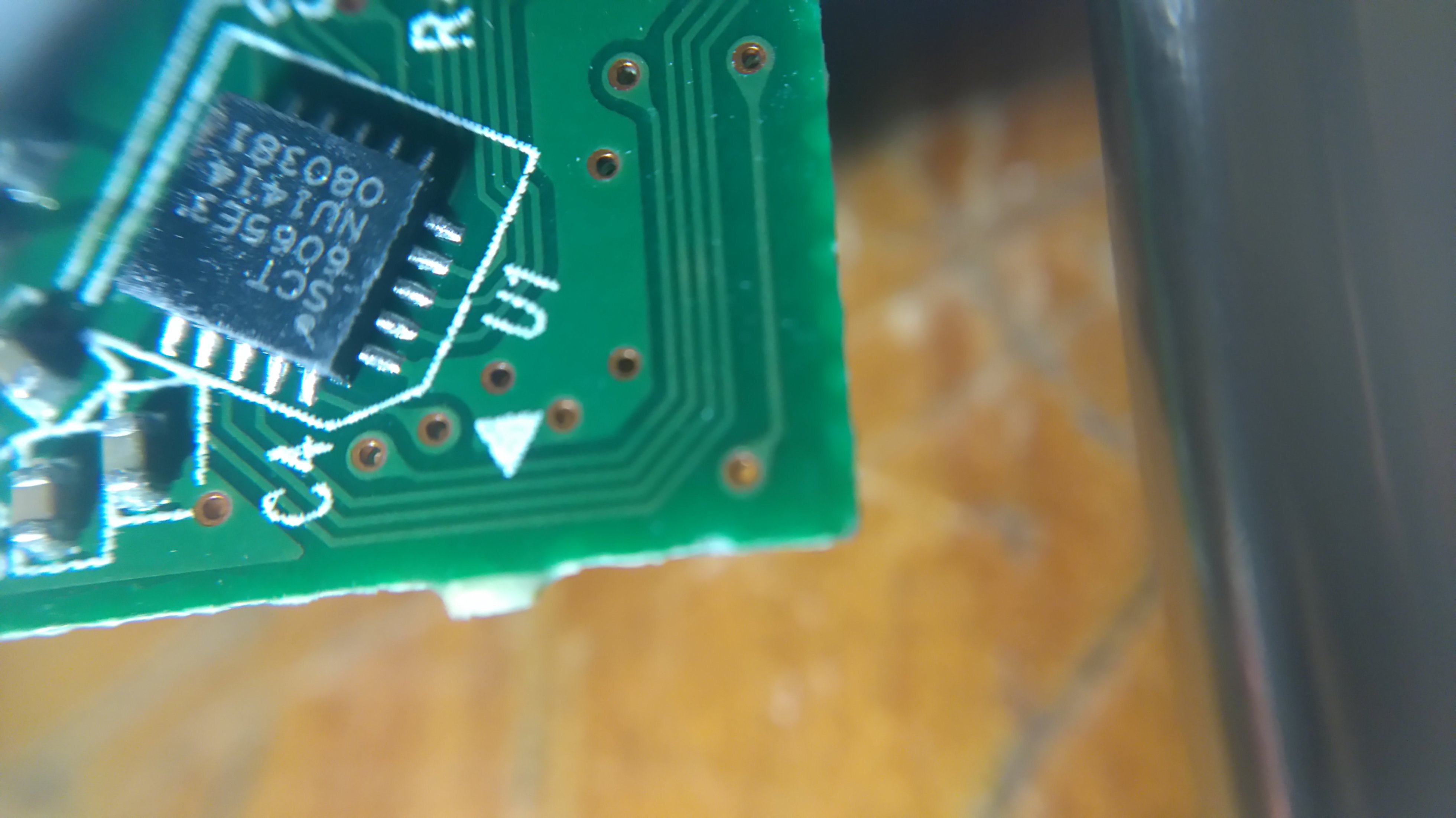
I spent a while checking pin-outs and following the PCB traces, but gave up my idea of using the built in drivers because a) I have a test today and don't need more diversions and b) I couldn't find this chip anywhere (if you know it, yell):
![]()
Anyway, I soldered some cable to the stepper and laser pins, and fired it up for a test:
![]()
Yaay, it's a red laser! BE VERY CAREFUL - sometimes you get IR lasers which can easily blind you. Red is still dangerous (this can burn paper and retinas with equal ease) but you at least know when it's on, and your blink reflex should save you especially when it's focused so that it spreads out (as in the image above). To drive the laser, I'm using the following circuit. I start with the current set resistance at 100 ohms, and moved down to ~16 ohms for now. I will find it's limits later - for now this looks bright enough and is well below the max so everything stays nice and cool and I don't burn it out accidentally.
So the plan is to use one of the stages from my old set-up, and use the built in laser for the toner melting process. I may also experiment with controlling the coils for focus, but that's for later.
One final thing: This is a team project! @esot.eric is also trying this out, so we'll collaborate and hopefully between us come up with something useful :)
Mini PCB printer
Melting toner (as etch resist) directly onto copper clad board using a laser moved by a DVD drive XY system.
 johnowhitaker
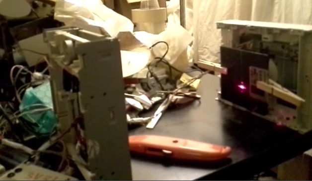
 And here's the laser-lens and slide-mechanism:
 I really think this technique has promise, and I hope I can take it further over the course of this contest.