Vijay
Vijay-
Motor-gasm : The most amazing motor on earth!
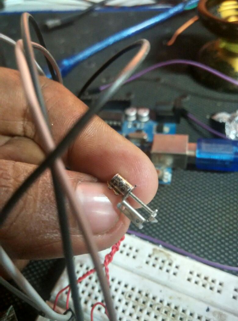
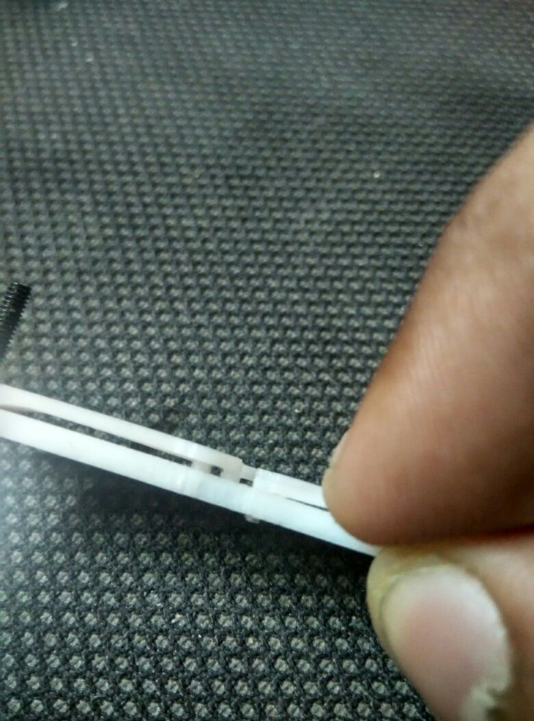
07/12/2016 at 20:20 • 9 commentsThe micro stepper motors I ordered just arrived, and god are they brilliant!
![]()
I did some rudimentary experiments about the amount of torque it has, and if it would suffice for my application, and I think it would, although i'm afraid it might miss steps.
I'm driving this straight out from the Arduino pins that should be ~40mA source and sink. Possibly some more juice from a proper driver will do the torque some good.
Let me know what you think. I would also like to thank all those who responded to my earlier log, especially @HTCPCP 418, whose micro stepper motor driver approach, ill probably be taking.
Ill be uploading CAD data for these motors in a few days if anyone is interested.
The link to this motor is : http://www.aliexpress.com/item/50pcs-2-Phase-4-Wire-Micro-15-Step-Motor-Screw-Rod-Stepper-Stepping-Motor-Free-shipping/32222560547.html?spm=2114.13010608.0.78.tjruAc -
Help needed driving multiple stepper motors.
06/26/2016 at 07:02 • 16 commentsWe are trying to figure out the best way to drive as many stepper motors simultaneously ( for the actuation system mentioned in the last post ) .
-There are 40 stepper motors in total for a 20 cell braille display, two per each cell. They preferably need to be actuated simultaneously.
-The motors do not require too much current ( unknown amount since there is no datasheet, motors will arrive in a couple of days)-The motors are 4 wire- Bipolar steppers, with 15 step a rotation.
-it takes roughly 25 rotations of the stepper motor to reach from one end of the linear selector system to another.
Some of the approaches friends have suggested:
-Using many stepper drivers like allegro or TI's solution each connected to a slave MCU like an attiny85, that takes serial input. ( i.e, each braille cell has stepper motor controller and a MCU)-Using a I2C, SPI port expander connected to a main MCU
-Using an LED driver
Any suggestions for this problem?
-
! New Actuation System !
06/22/2016 at 20:42 • 3 commentsI've been straight at it, thinking about alternatives for the last actuation system after last weeks events. I think ive got a good robust system this time, that actually is simpler than the last one in terms of components and size. Lesser parts to be 3D Printed, and more that can be bought off-the-shelf
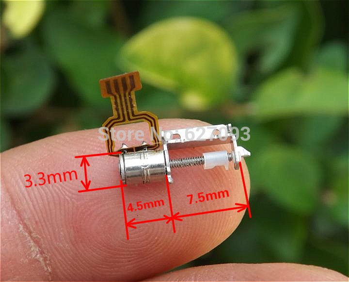
Using![]()
Micro Stepper Motor
+
![]()
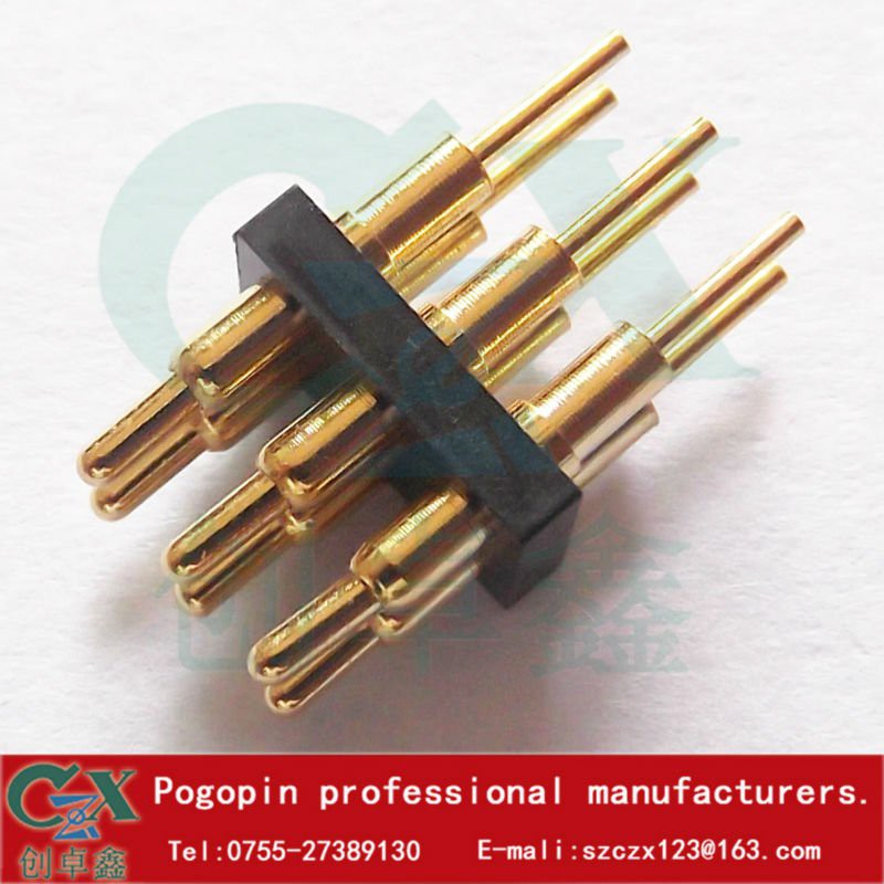
3x2 Pogo pins
=
Using retractable pogo pins, that are engaged/disengaged using some sort of linear motion ( servo/ stepper/spring/solenoid for up and down motion) that pass though a pin-selector slider mechanism that allows only some select pins to pass actuated by the micro stepper motor.
note: once an array of these is built, the engaging/disengageing ( up and down) motion of the pogo pins can happen simultaneously( for all braille cells together) with a since actuator.
What do you think? -
Discontinuing work on current actuation method
06/18/2016 at 20:51 • 3 commentsHi all,
As mentioned in my previous post, it’s been brought to our attention that features of the open source refreshable Braille display project have already been covered under a patent application filed by Paul D’souza on 5th November, 2014.
Paul’s patent describes the use of “micro-motor actuated pins, the pin cantilever design, the mechanical stop to limit rotor rotation, motors with rotors or cams, mounted vertically or horizontally used to lift pins directly or via an interposer, low force selector etc” - many of these are featured we have included in this device.
Paul has requested we discontinue the project in the interest of potential manufacturers and licensees of his patent, as well as to avoid any legal obligations he may face with the patent office. As a result, the CERN Open Hardware License the project was released under has effectively been invalidated and so I have discontinued work on this current method of braille pin actuation. The patent will severely restrict any global (and particularly local) impact we can make with this project, which was our whole motivation.
However, I would like to make clear that the designs and documentation we have released have been created from scratch, sharing only the working principles of Paul’s patent. My intention has always been to make a completely 3D printable refreshable braille display that anyone can access and I have been working on braille technologies for the past three years. As part of this work, I have developed software to convert text documents to braille and built two refreshable braille display prototypes, one using micro servo actuators and another using a hacked dot-matrix printer head. At that time, I was still a kid in college and didn’t have much knowledge about production techniques or skill in design, CAD, and electronics.
Things have changed a lot since then. Going through the process of setting up and running a 3D printing and product design startup, I’ve learned exactly what I need to know to create just about anything. I actually met Paul at a local Maker Faire and we instantly connected because of our shared efforts on braille and I was amazed and intrigued by his genius ideas for actuation. This meeting resparked my passion for braille and I began using cell-phone vibration motors as a method of actuation along with my experience with FDM 3D printing and product development to create a solution that anyone in the world could potentially have access to just by downloading the files.
What’s more, I was lucky enough to have the opportunity to show one of my early braille display prototypes to the president of India, Dr. APJ Abdul Kalam, before he passed away. He made me promise that I would do everything in my power to ensure the project would reach the people that it matters most to and that has become my life's mission ever since.
Since the 3D designs and documentation are my own original intellectual property, I will be releasing everything under Creative Commons Attribution-shareAlike 4.0 International. This is an open source license that allows anyone to use, modify, and share the documentation and 3D designs under the same license. However, anyone wishing to manufacture and distribute the device itself should contact Paul D’Souza on pgdsouza@gmail.com. I have done this to ensure that people can make a personal copy for studying purposes.
I will certainly not stop working on the refreshable braille display due to this hiccup. I have seen some amazing motors from Aliexpress while buying motors for the current system and I am confident that by collaborating with other members of the open hardware community we come up with a “patent infringement free” solution that is feasible, scalable, and will achieve my goal of bringing digital literacy to the visually impaired all around the world.
I wish @PAUL DSOUZA all the best, he has been incredibly supportive on this project, and multiple others my team and I have been working on. I formally apologize for any inconvenience caused to him.
Big thanks to @K.C. Lee @Radomir Dopieralski @Yann Guidon / YGDES @Martin and so many others who have been supporting the project. Its been awesome.
Links to my past work mentioned in this post:
https://campusdiaries.com/stories/virtual-brailler
https://www.youtube.com/watch?v=zTp81kkJXo0
http://www.angadmakes.com/my-portfolio/virtual-brailler
http://note.taable.com/post/9050C/25Under25-Finalists/2b-39849079446937193874TT76TT4T76
-
Updates!
06/17/2016 at 15:26 • 1 commentOn suggestion from @Yann Guidon / YGDES I've scaled the mechanism by 1.1 times. It changes the dimensions by a very small amount (0.6mm over a character) so that I can accommodate 4mm motors for the time being since the 3mm ones are proving hard to find. I shall maintain another copy of this version of the mechanism in another folder.
Using the prize money from the "Anything Goes" round ( YEY!) ive purchased the following motors and eagerly await their arrival:
The electronics design will take advantage of the spring leads of the motors to have a "solder-less" connection to the driver board. As mentioned in an earlier post, it driver circuitry will be similar to that used in Flip-Dot displays (Thanks Martin )
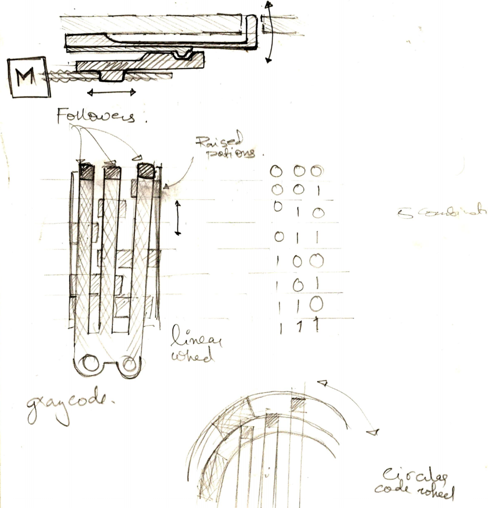
I have been requested by @PAUL DSOUZA to make everyone aware that the features mentioned in this Project thus far are covered under a patent application filed at The PatentOffice, Chennai, by him on 05Nov2014 …5559/CHE/2014. If anyone wants to exploit features of this design, they would need to get in touch with Paul or his patent attorneys (Origiin IP Solutions LLP), as rules require that even the Patent Office to be kept informed of activities in regards to patents.I have also been toying with the idea suggested by @Keith Minsel using cams to drive the pins. After finding some really cool motors on aliexpress (God bless China) Ive made up my mind to make a prototype using a stepper-cam system to lift pins up and down.
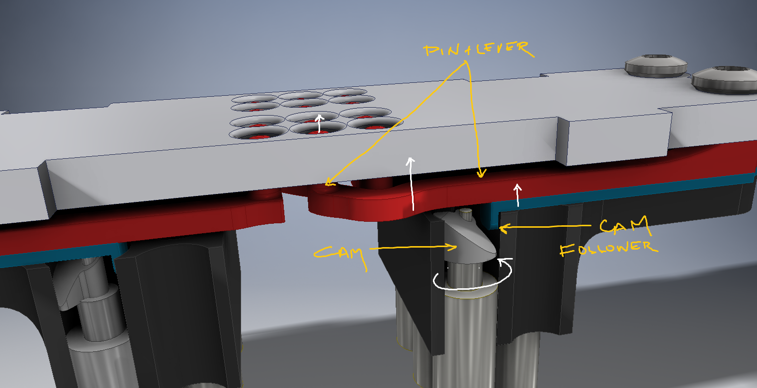
I'm considering using either a linear compound cam, on a circular one. I hope people can decipher the drawings above, The prongs are the same cam followers that I have currently on the design, only the motor block would be replaced. Any help with making the decision is appreciated( circular or linear)![]()
The stepper motors: http://www.aliexpress.com/item/hot-salow-price-20pcs-extra-Micro-stepper-motor-DC-Stepping-motor-with-Screw-Dia-3-3mm/2053510670.html?spm=2114.10010108.100009.4.UGX6T0I guarantee the size would surprise you.
-
Thats one tiny motor!
05/12/2016 at 17:30 • 0 commentsI found a single 4mm dia motor from somewhere, and am in the process of modifying to see if it works. it struck me how small these things are!
![]()
I'm also in the process of working out the electronics, looking at how Flip Dot displays are run, and probably follow the same method for the driving circuitry.
Using the following resources for that ( Thanks to Martin for the idea) :
http://www.dhenshaw.com/Art/Dottie/start.htm -
Pin actuation looks promising!
04/29/2016 at 12:06 • 2 commentsI couldn't get the motors I need, but was able to source a 6mm dia version (double the size I need) to see if the cam+follower thing would work, I just couldn't take the suspense of not knowing!
I was too lazy to CAD anything for the test, I had to know IMMEDIATELY!
so I ground the weight to a shape I wanted, got my friends iPhone to record in slow mo, and it looks promising!
I can't be 100% sure the final would work, since the actual motors I need to use are smaller, but I feel it's got a fighting chance!
I also realised I'm using 2 simple machines, a lever and a ramp, and it oddly satisfies me for some reason.
Inferences:
- there is only a ~0.5mm lift required at the cam follower to achieve the required lift at the pin.
Hence, a shallower angle on the cam, would make it even more easier to lift the pin ( because of the shallower slope of the ramp of the cam )I contacted sales at Precision Microdrives about sponsoring their motor, https://pmdri.zendesk.com/attachments/token/koNuCT5zcZuO6kQC6E56rh040/?name=303-103-datasheet.pdf
They got back saying they won't lower the MOQ or the price :( gotta figure out another way of getting my hands on them, or else try and change the design to use 4mm dia motors from china ( highly unlikely they will fit the requirement due to the size constraint)A big thanks to @Anool Mahidharia for the article on Hackaday today!
http://hackaday.com/2016/04/28/refreshable-braille-display-and-braille-keyboard/ -
CAD design changes and improvements
04/27/2016 at 21:22 • 0 comments![]()
Updated the description with the above image. As you can see, the changes in the last few logs now reflect the CAD design.
-The Cam Follower(blue) & Pin Lever(red) are different parts to aid 3D Printability-Jig-saw type thingies on the sides, for chaining the module to create a full display
-
Cam followers+ Spring action working!
04/24/2016 at 15:45 • 0 commentsThe cam followers were printed, and came out beautifully . The Spring action works just like planned.
the only thing left to test is the cam actuation with the motor.Link and description of the motor :
https://www.precisionmicrodrives.com/vibration-motor/3mm-vibration-motor-8mm-type
The MOQ and price is a little expensive for me at the moment, I will be contacting them and asking if they will sponsor the motors for the project.The video below shows the cam followers and the spring action pulling the pins back down after pushing the cam followers up.
-
The perfect tolerances: Assembly time!
04/19/2016 at 18:32 • 0 comments![]()
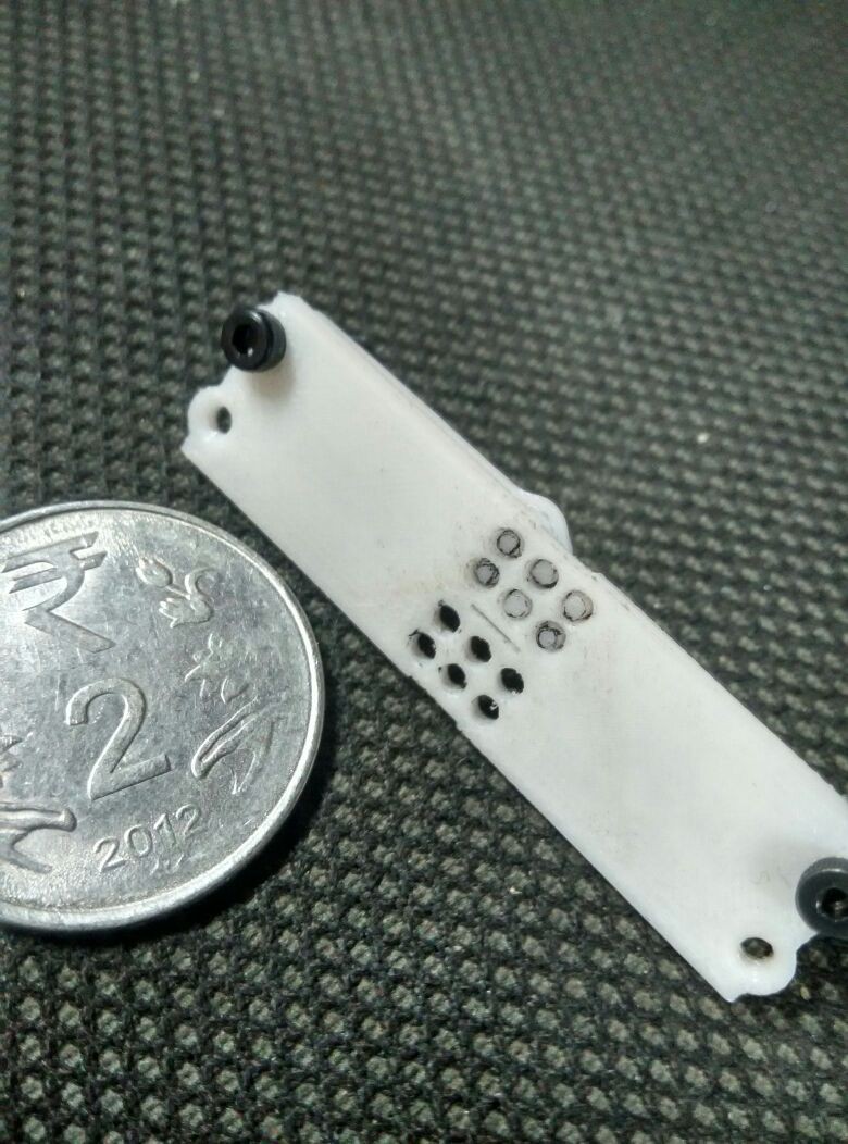
The above image shows the shaft-lever part into the braille cell plate. It took 4-5 iterations (available on the dropbox link) to get the tolerances just right, such that the pins don't get stuck in the shaft of the braille cell plate.
![]()
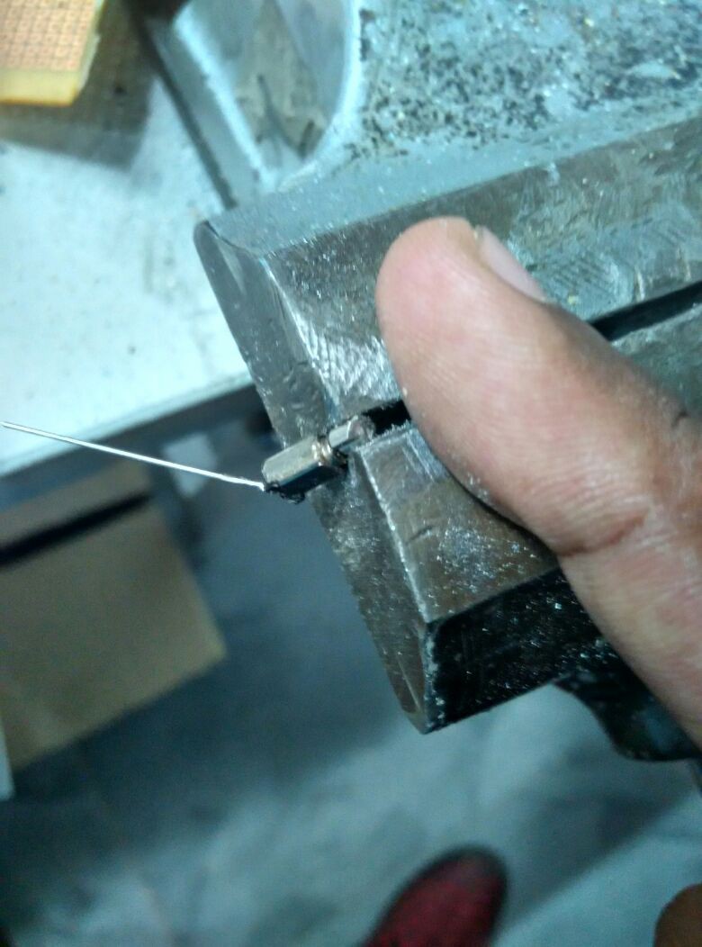
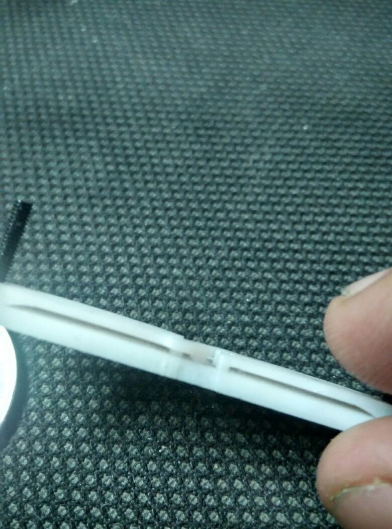
The above image shows the side view of the braille cell's, along with the pin-lever part assembled and held in place with an M2 screw. the pins are "below" the surface of the braille cell plate when not pressed, due to the spring action of the lever ( by the cam follower)
![]()
In the above image, I'm applying a slight force on one of the lever, that causes the pin to move up. Quite simple really.
Now its time to test with motors!
Refreshable Braille Display
A cost effective way to make a refreshable braille display