Austin Marandos
-
Final Design, and Final construction
04/11/2016 at 04:21 • 0 commentsOnce all the adjustments had been made it was time for the final construction. The parts were once again cut out on my School's laser cutter. All the perspex pieces were glued together using perspex glue.
![]()
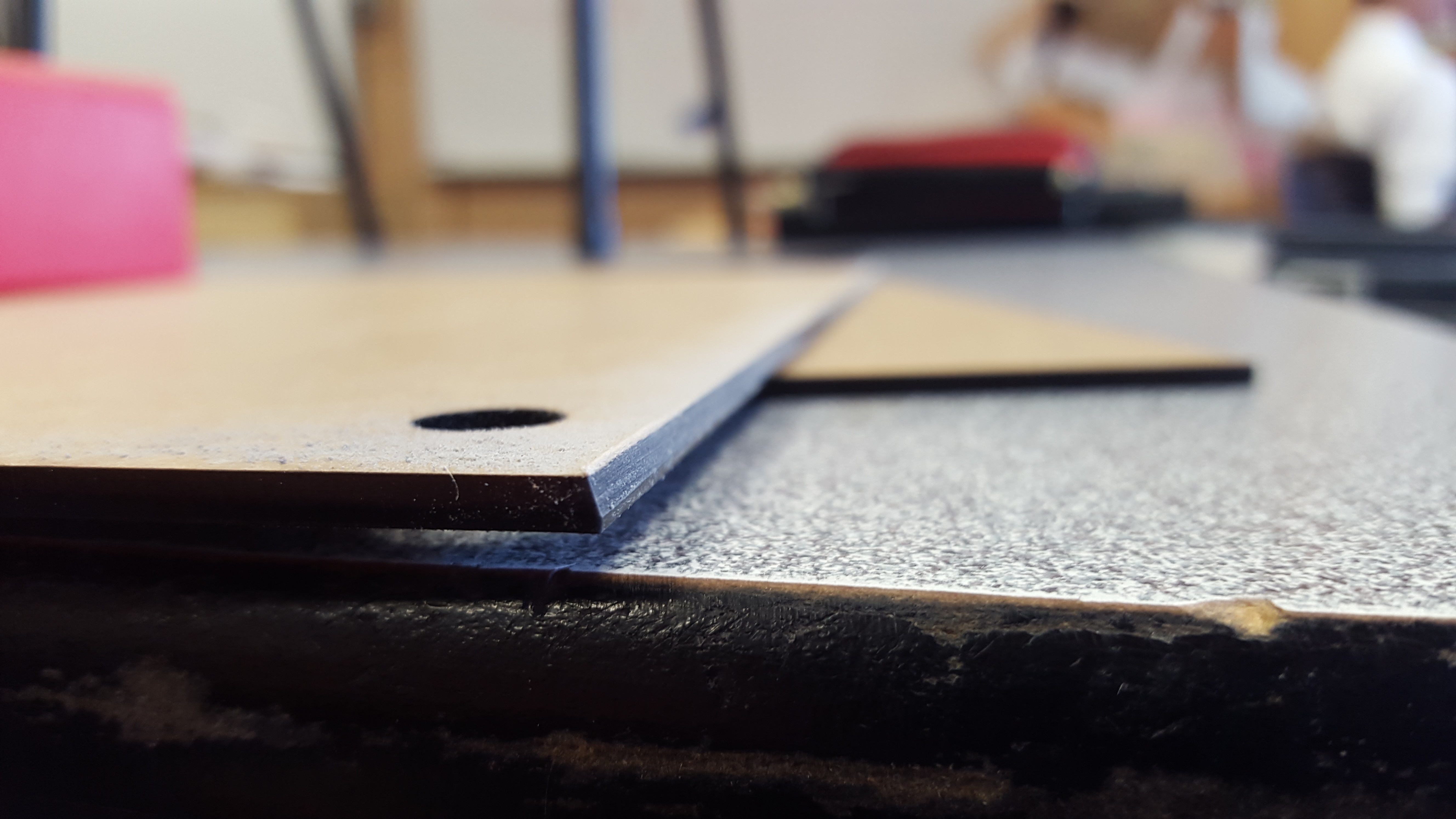
The front and back panels had to be sanded down by 75 degrees since it is shaped like a trapezoid:
![]() Construction of Perspex pieces:
Construction of Perspex pieces:![]() All pieces assembled (with protective cover on). Note: it has not been glued yet since not all the electronics had been installed
All pieces assembled (with protective cover on). Note: it has not been glued yet since not all the electronics had been installed![]() Installation of LCD and Electronics:
Installation of LCD and Electronics:![]() Fan installation: (the fan was pointed directly at the LCD driver IC). There was also a vent on the opposing side.
Fan installation: (the fan was pointed directly at the LCD driver IC). There was also a vent on the opposing side.![]()
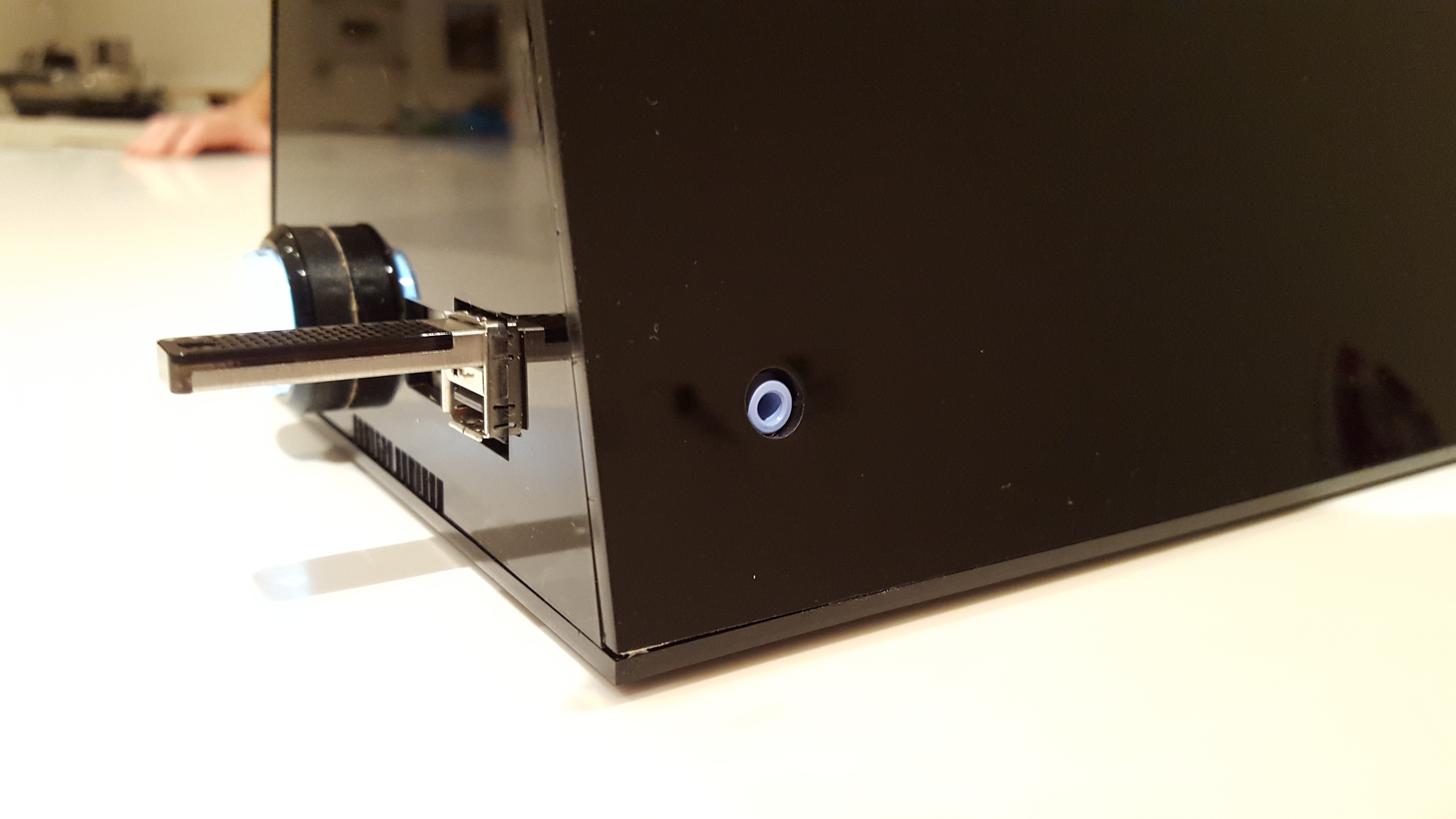
USB, Internet, audio connections and illuminated power button (arcade button from Adafruit).
![]() The top panel had two magnets, this was essential as there was no other way of accessing the electronics.
The top panel had two magnets, this was essential as there was no other way of accessing the electronics.![]() Matching interior magnet:
Matching interior magnet:![]() "See through" top panel:
"See through" top panel:![]() Final design:
Final design:![]()
-
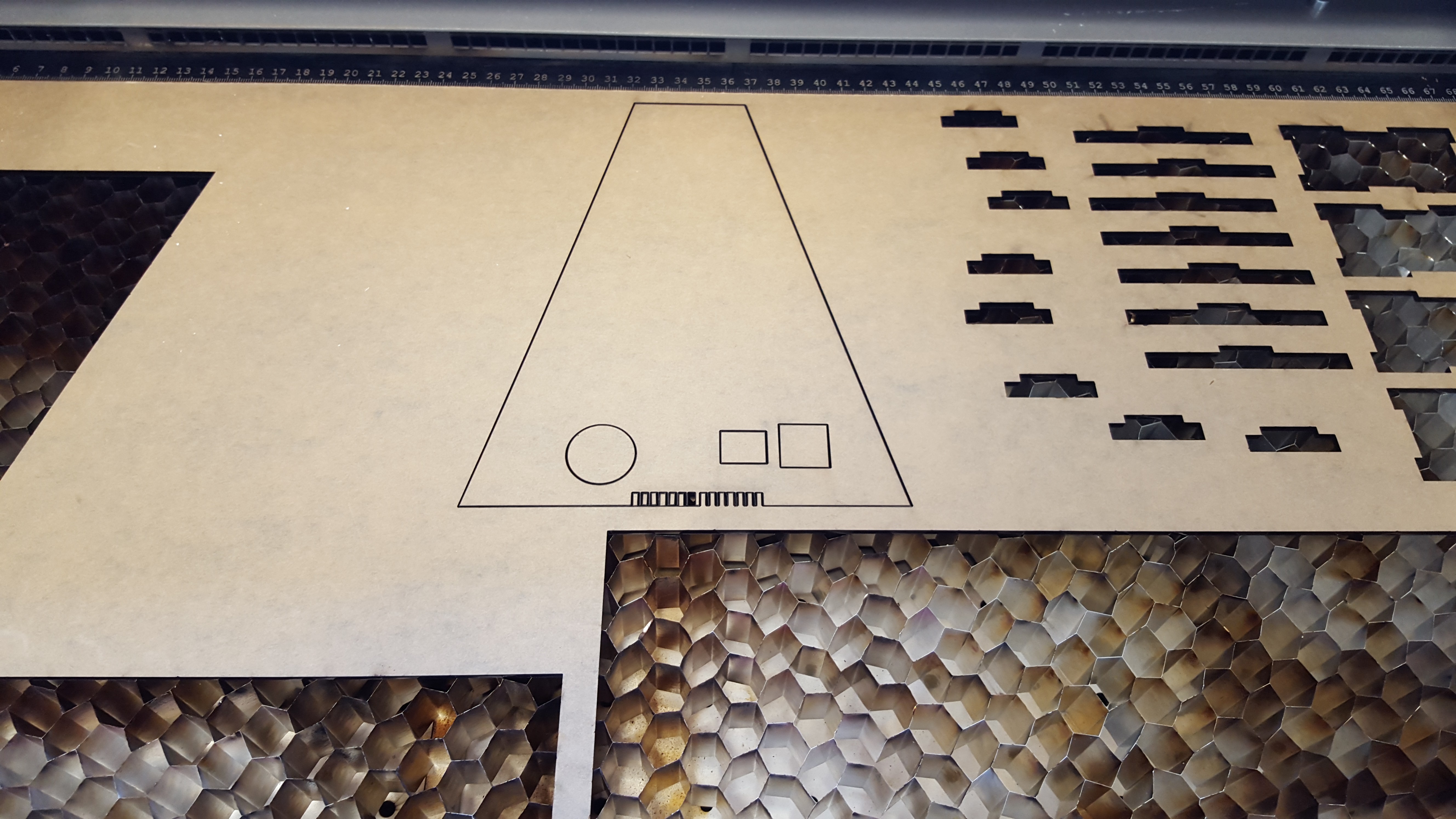
Prototype model
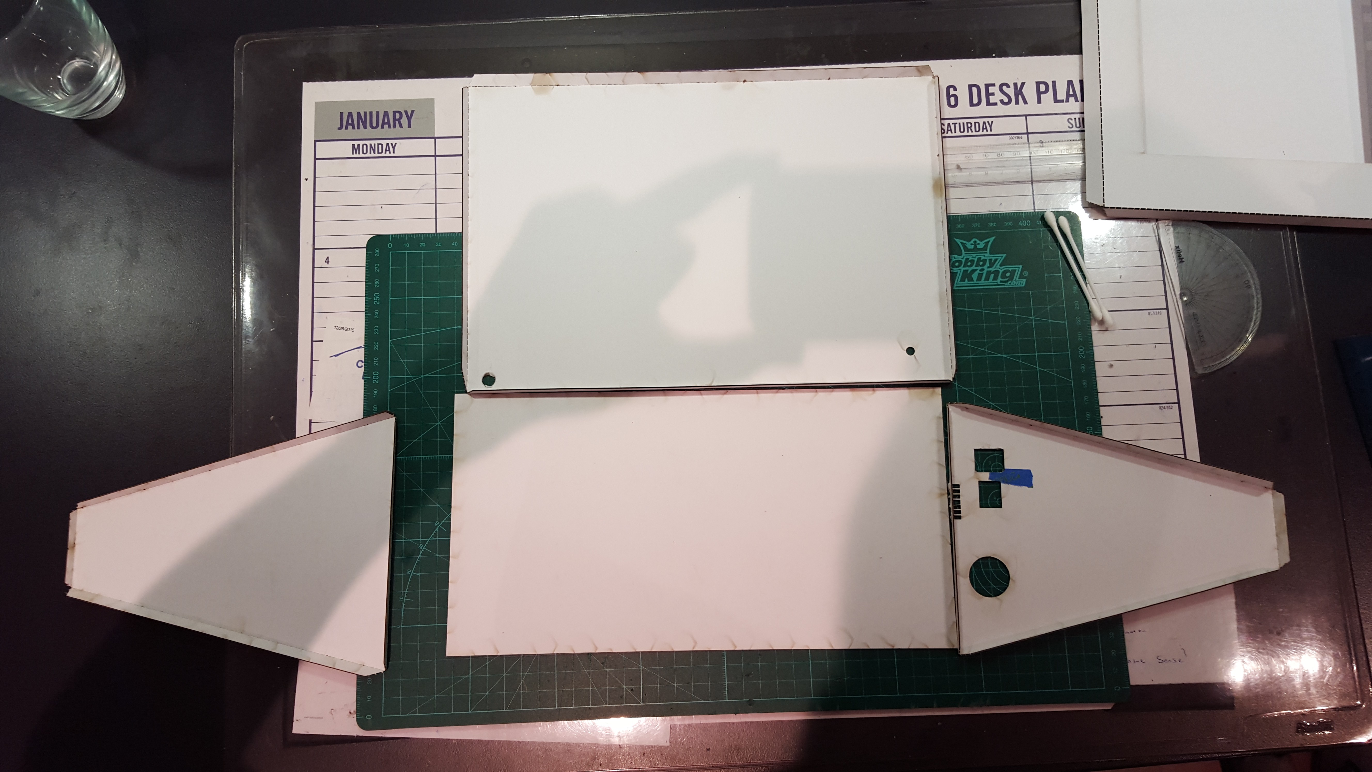
04/11/2016 at 04:02 • 0 commentsThe next step was to create a cardboard Prototype model, this was necessary as it allowed me to ensure that everything fitted and worked in the real world. I used my School's laser cutter to cut out all the parts for my photo unit from my Solidworks files. I realized very quickly that a lot of my dimensions were wrong....
![]()
![]()
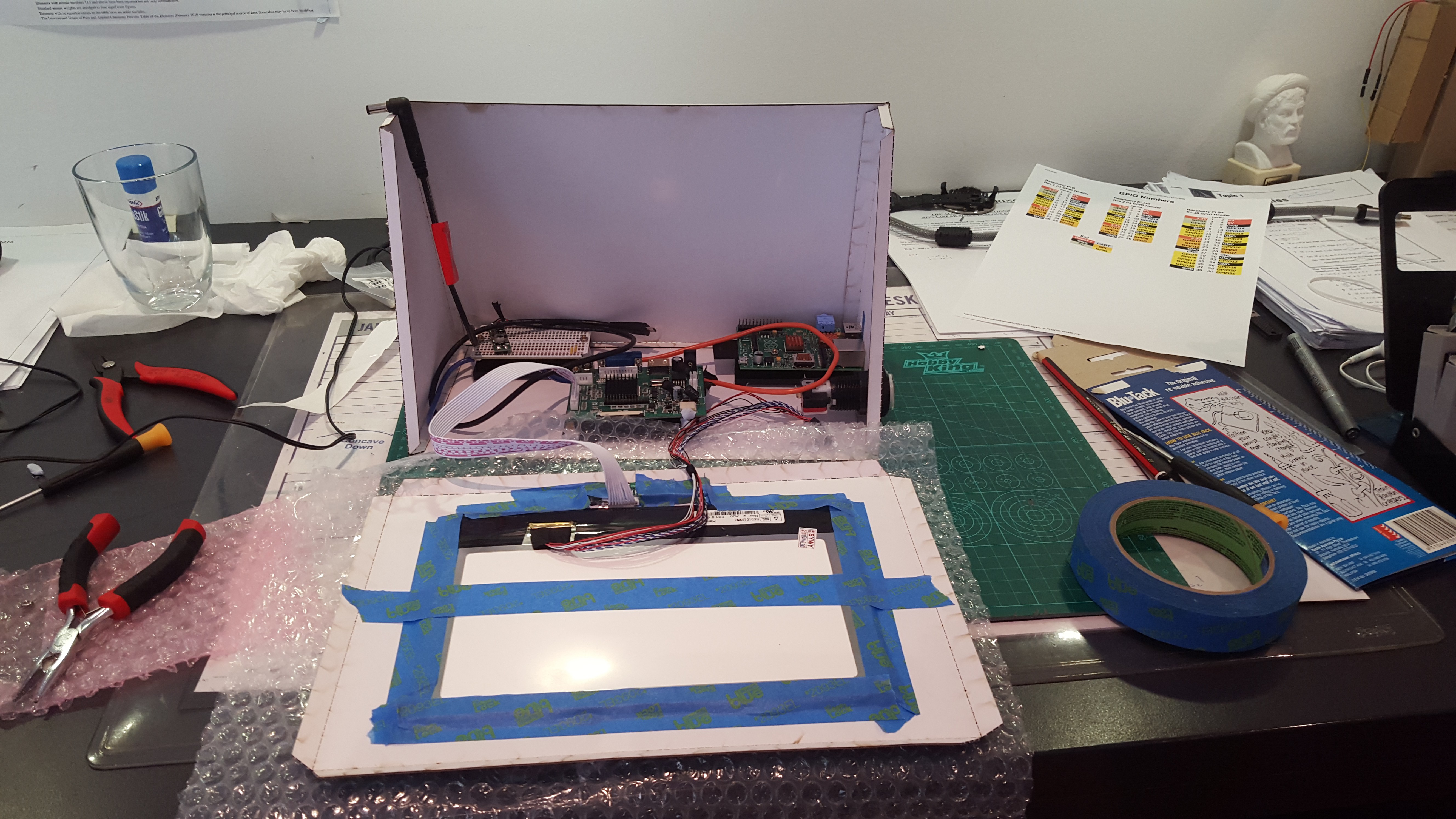
Installing all the electronics (including the LCD) and the very messy desk........
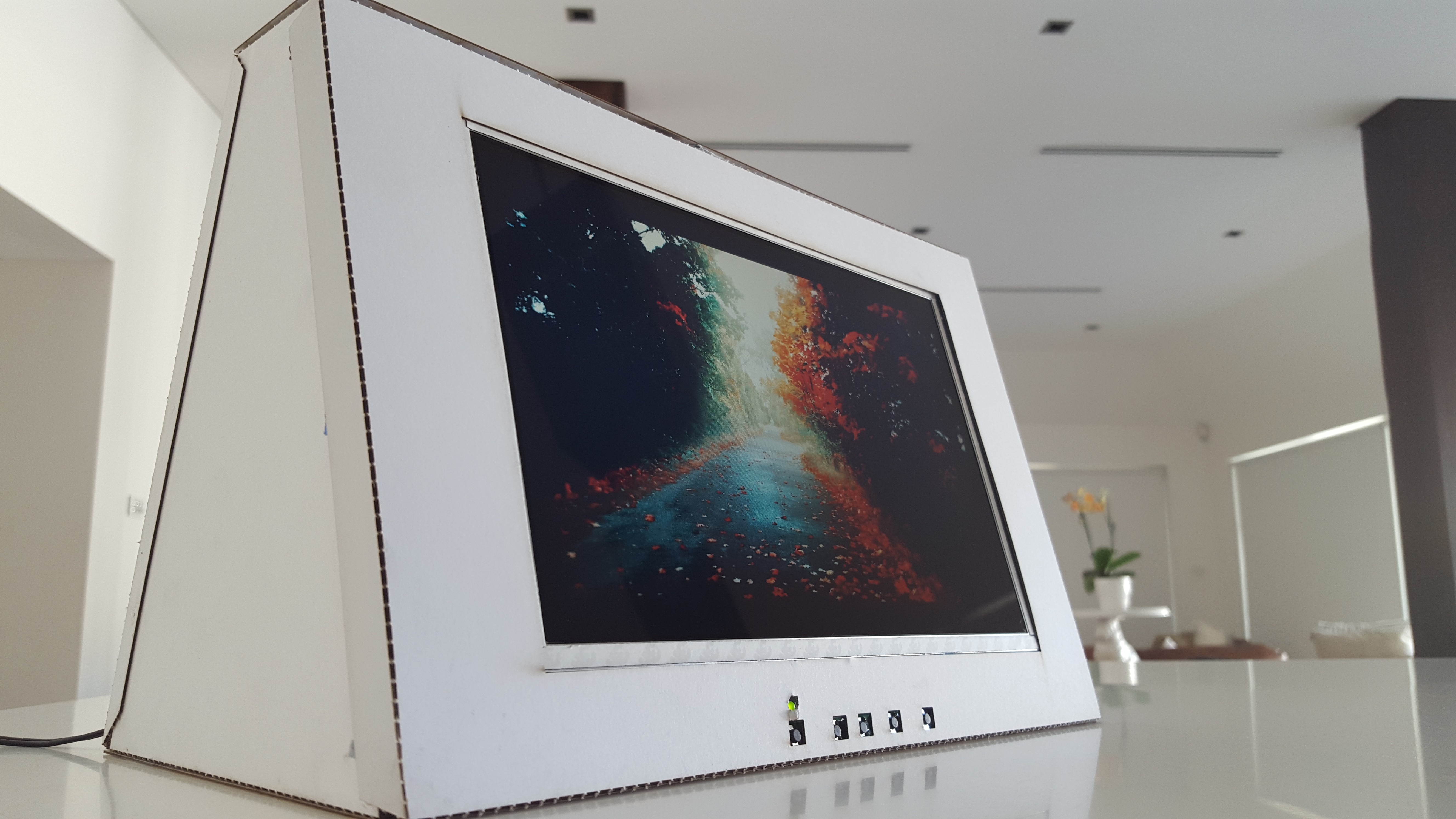
Final prototype:
![]()
-
Circuit construction and programming
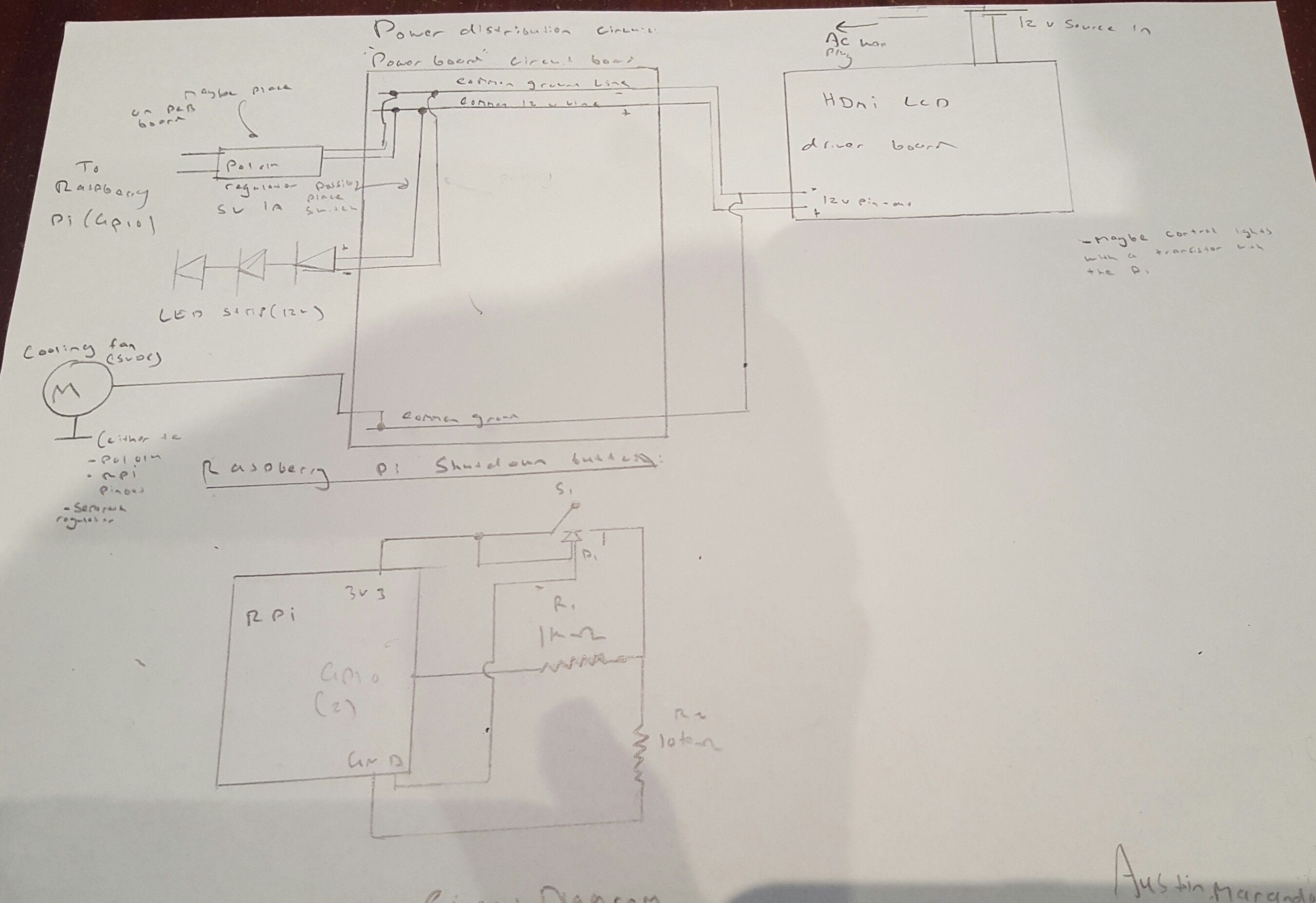
04/11/2016 at 03:47 • 0 commentsOnce my design on Solidworks had been created it was time to construct the circuitry and program the Pi. The first step was to design and draw a circuit diagram,
Circuit schematic:
![]()
![]()
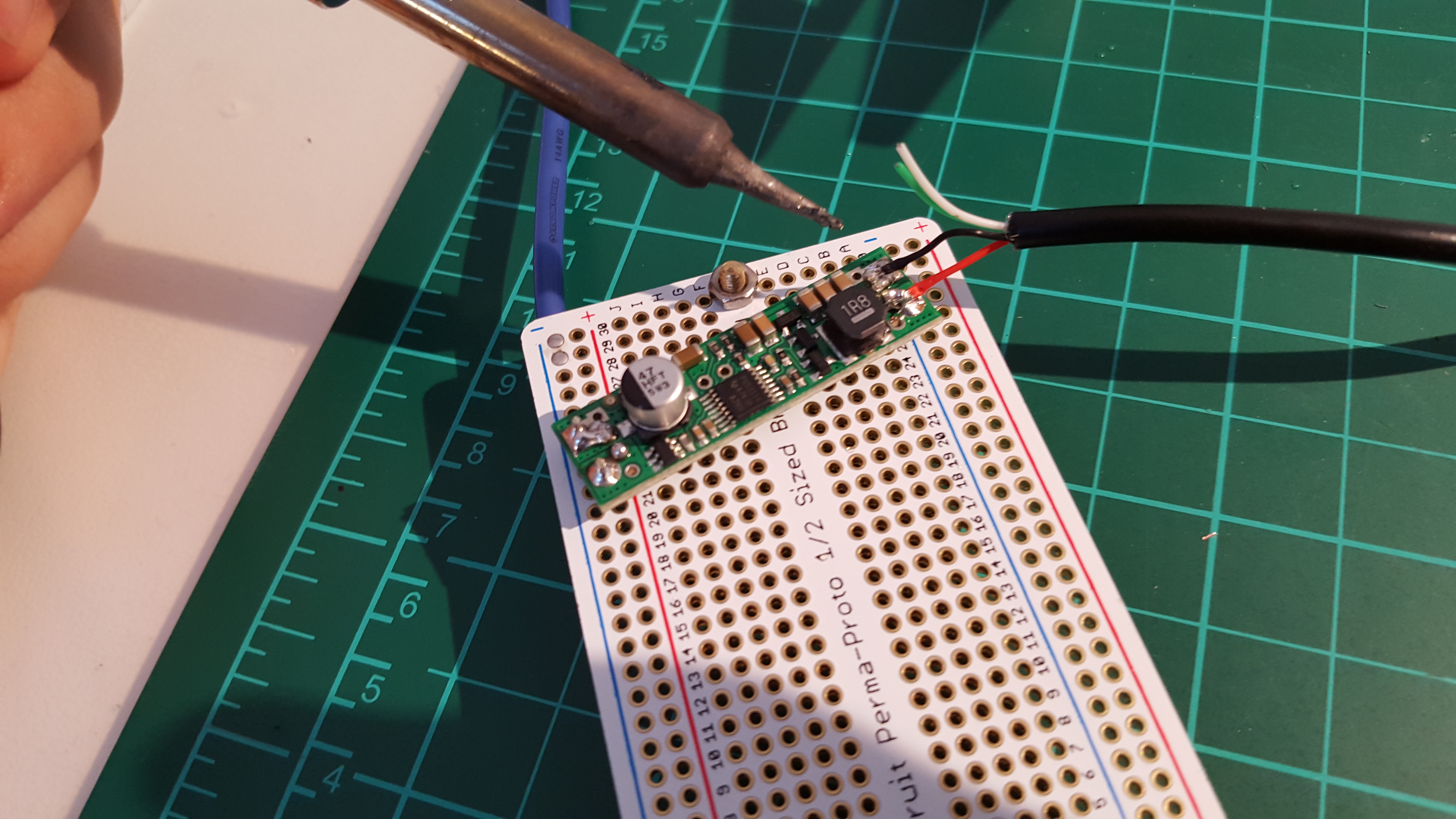
5V Regulator circuit. This is actually a motor regulator circuit but it worked fine on this project. Also it came with added heat monitoring circuitry
![]() An finally the 5V micro cooling fan. This thing actually worked wonders, it increased my Pi's performance drastically even though it was located at-least 5cm away from the Pi's CPU
An finally the 5V micro cooling fan. This thing actually worked wonders, it increased my Pi's performance drastically even though it was located at-least 5cm away from the Pi's CPU![]()
Programming:
Most of the programming was completed following Gus' video from "Pi up my Life", his video which is linked in my sources section was extremely helpful and allowed me to begin the "Fe" image viewer upon boot up.
However due to the nature of my project I needed a USB to mount upon boot up and read all the images for the Feh image viewer from the USB. I also needed to create a python code that allowed a button to safely shutdown the unit.
The code and helpful contributers will be linked on the project page
-
CAD Drawings (Solidworks)
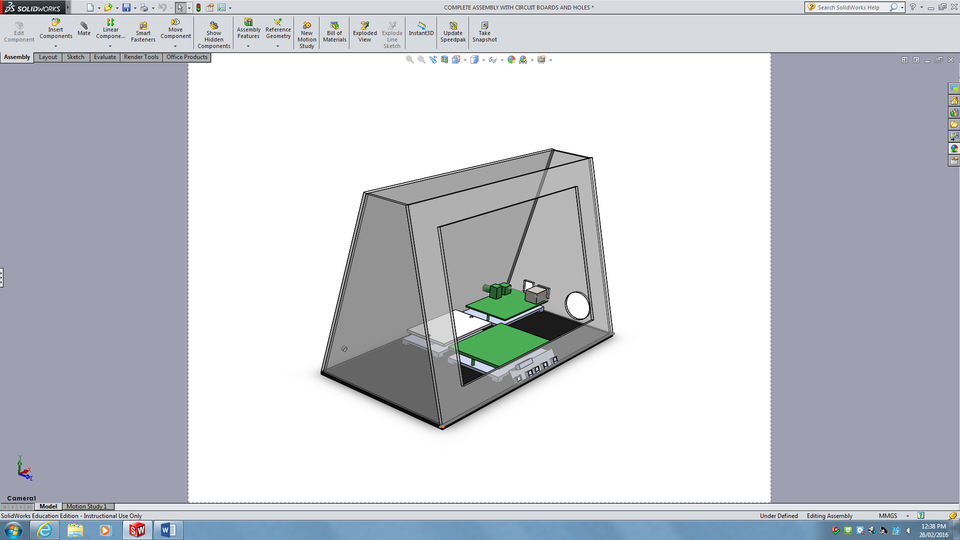
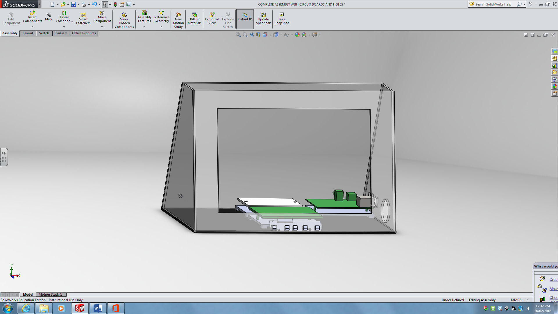
04/11/2016 at 03:33 • 0 commentsSince I used perspex I needed a way of creating the files that were to be sent to the laser cutter. I used solidworks for my cad drawings, I firstly made a 3D model of my entire design to ensure that everything fitted. I also had to create every single circuit that I used in my design in 3D in-order to make sure that they fitted.
Note: The holes for the power switch, USB, Ethernet and Headphone jack had to be calculated all on the CAD drawings, this was essential since I needed to ensure that I could access all the features of my Pi
Entire 3D design:
![]()
Overall Orthogonal view![]()
![]()
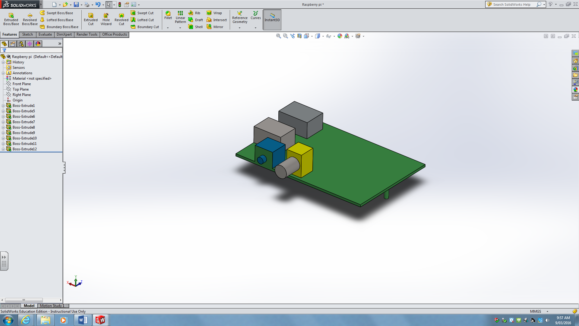
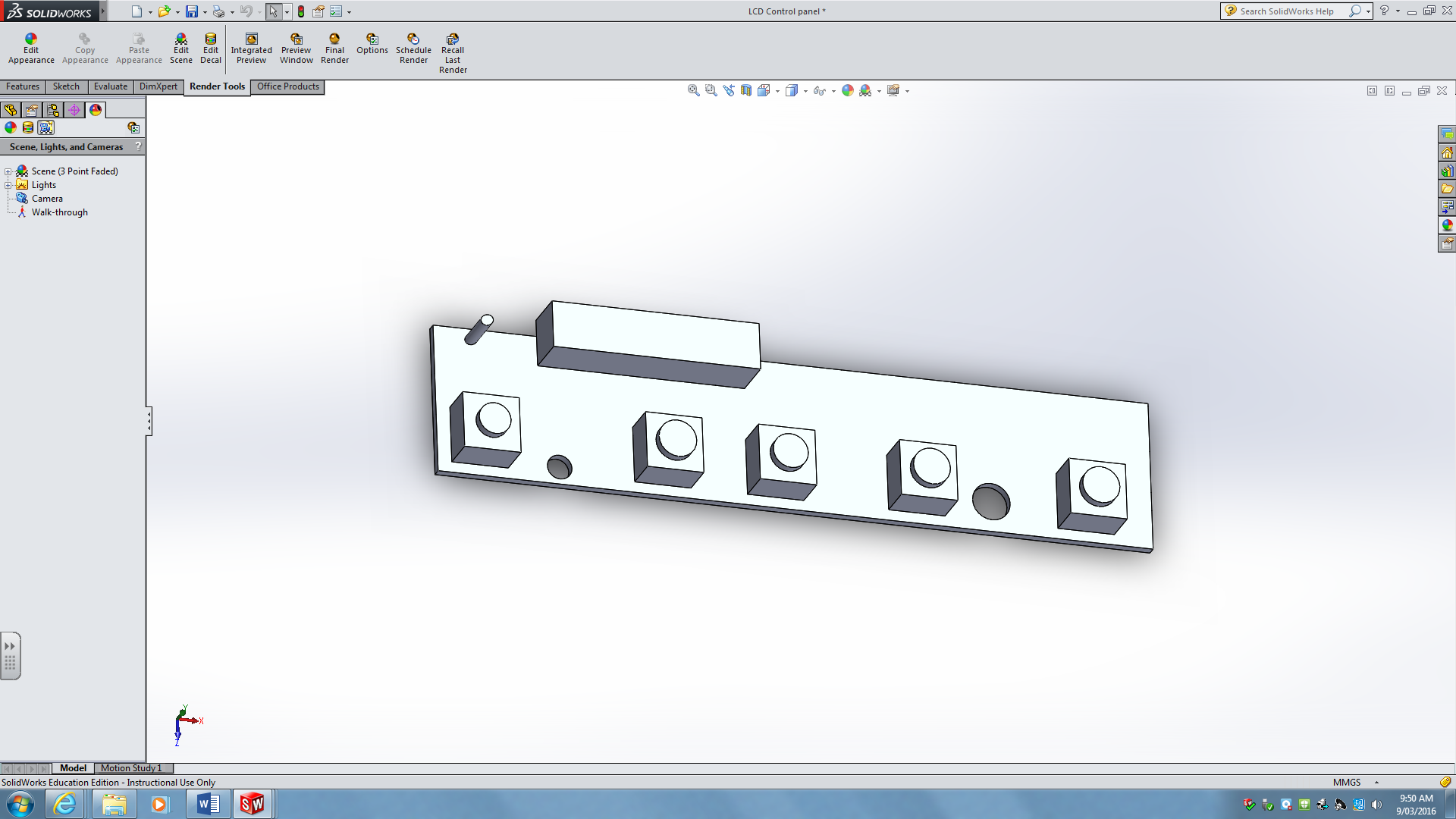
Individual 3D circuit boards:
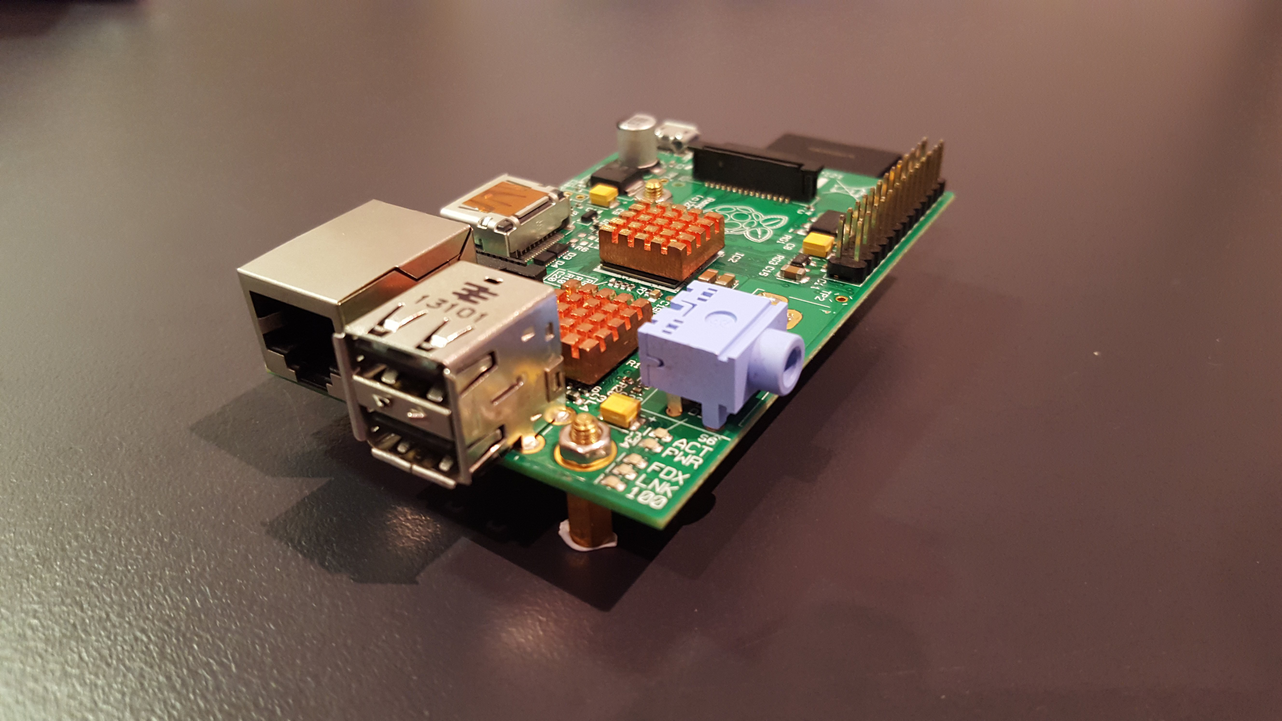
Raspberry Pi:
![]()
LCD Control board ^^![]()
-
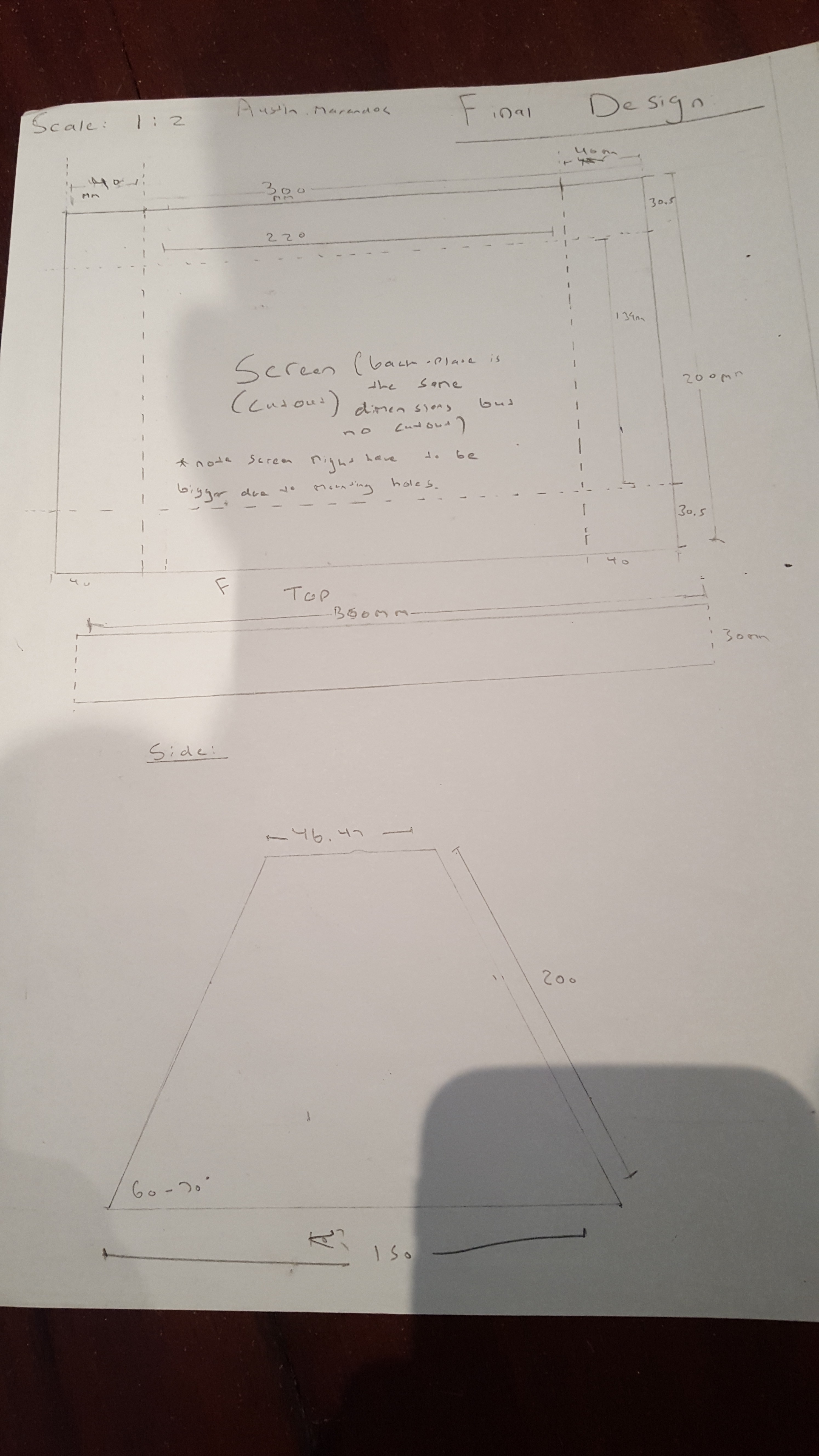
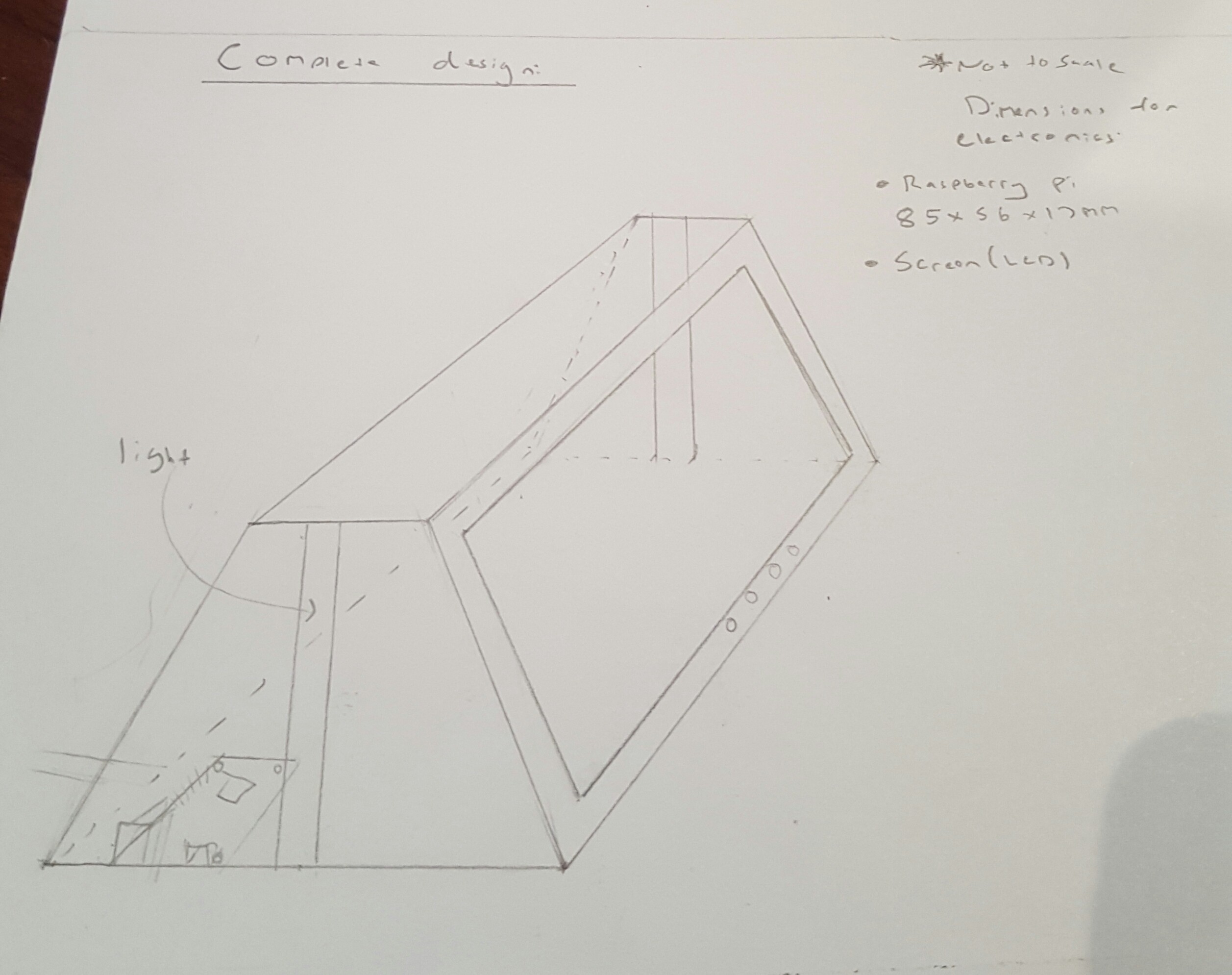
Initial ideas, and sketching
04/11/2016 at 03:16 • 0 commentsAs with all ideas the "Trapezoid" started out as a simple sketch.
![]()
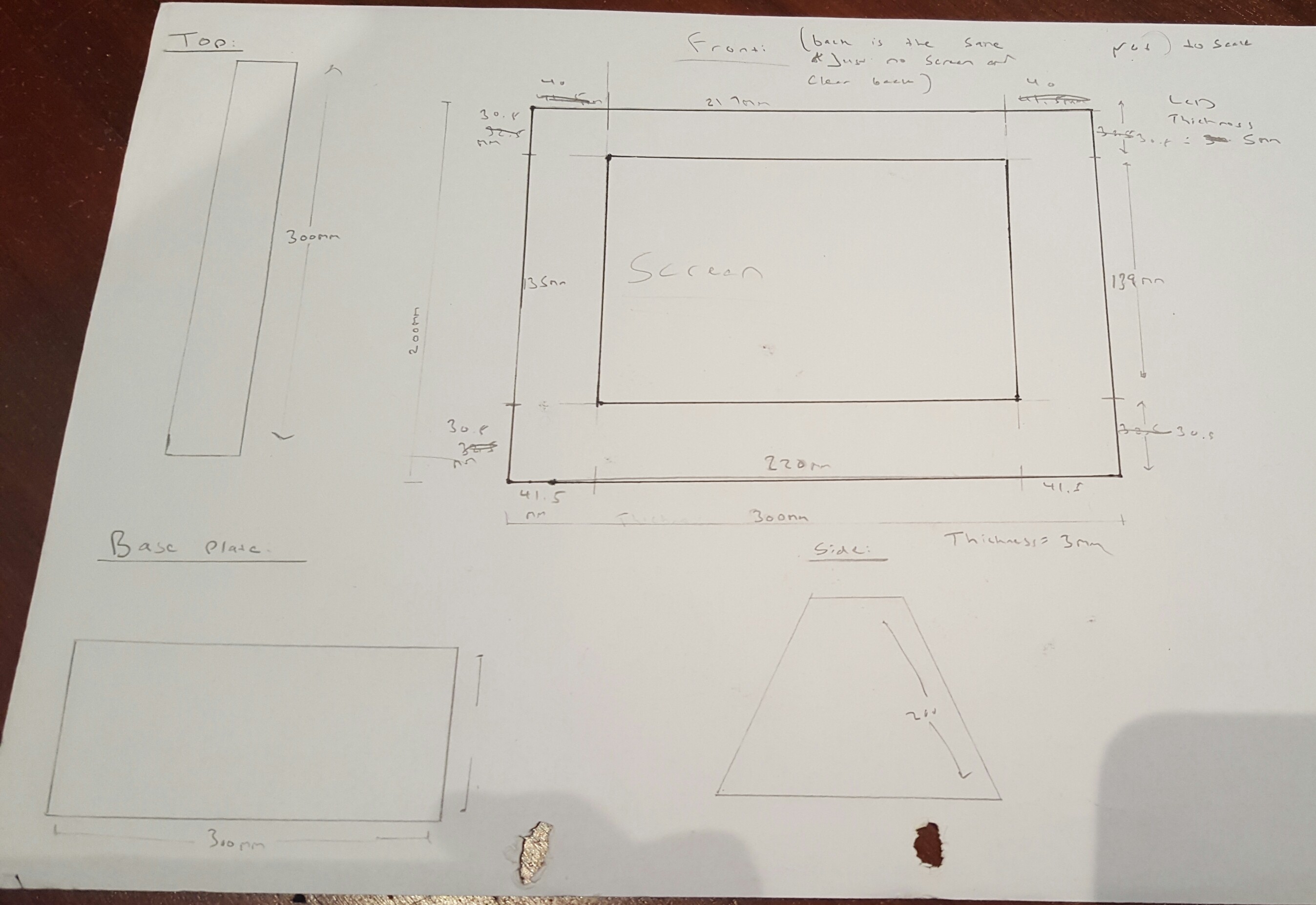
After the idea has been thought of orthogonal drawings needed to be established.
![]() And more....
And more....![]()
 Construction of Perspex pieces:
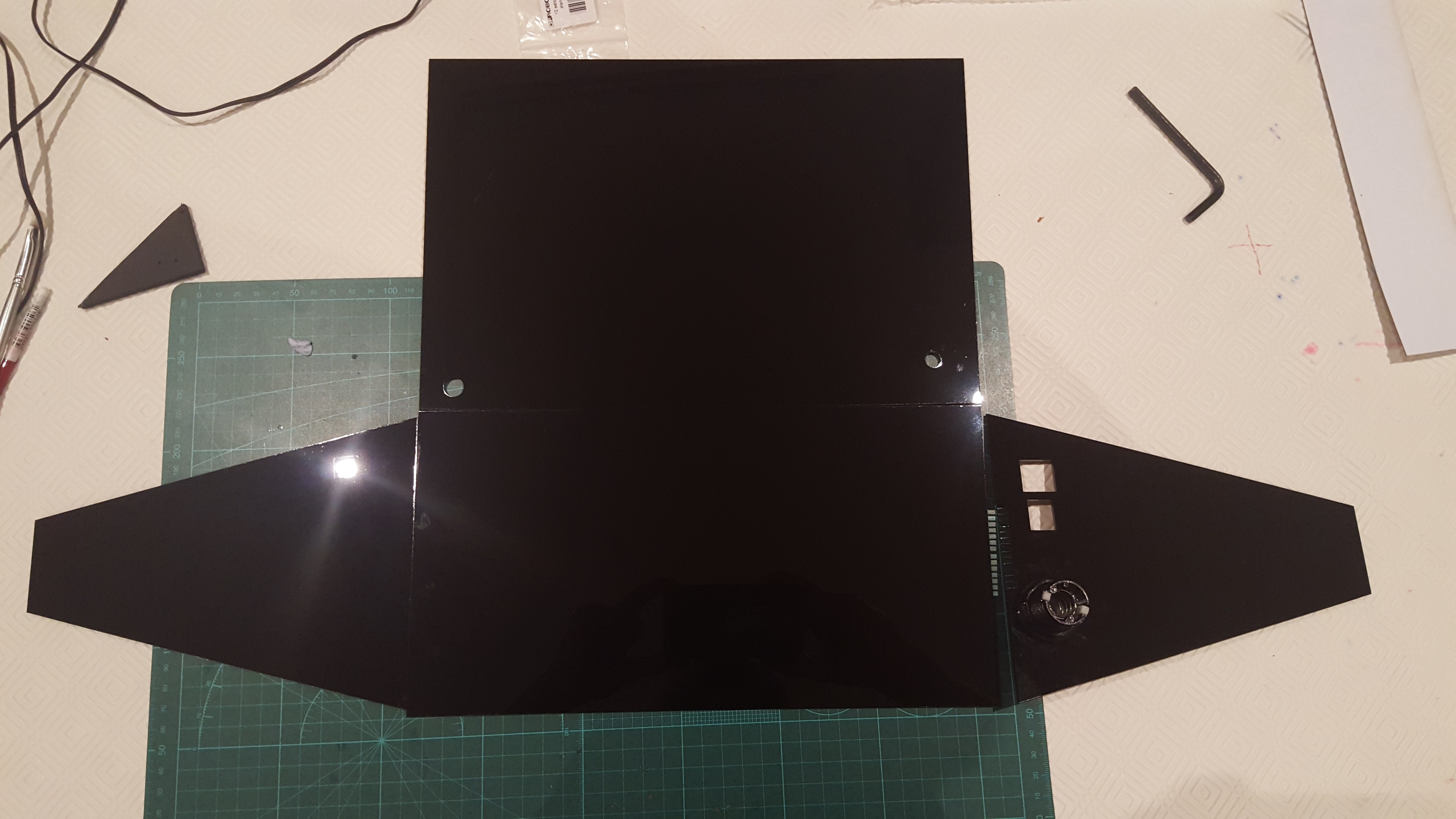 All pieces assembled (with protective cover on). Note: it has not been glued yet since not all the electronics had been installed
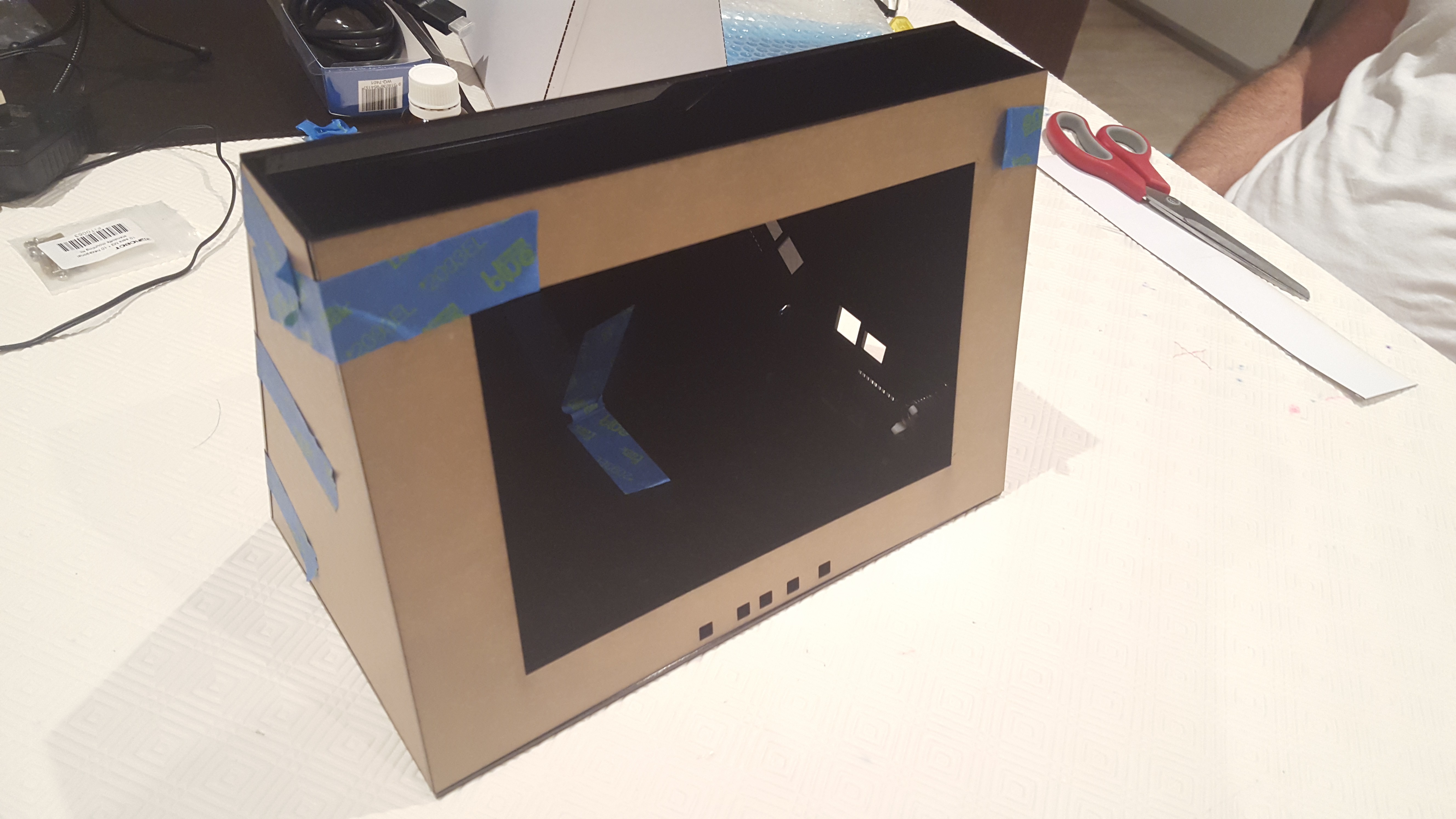 Installation of LCD and Electronics:
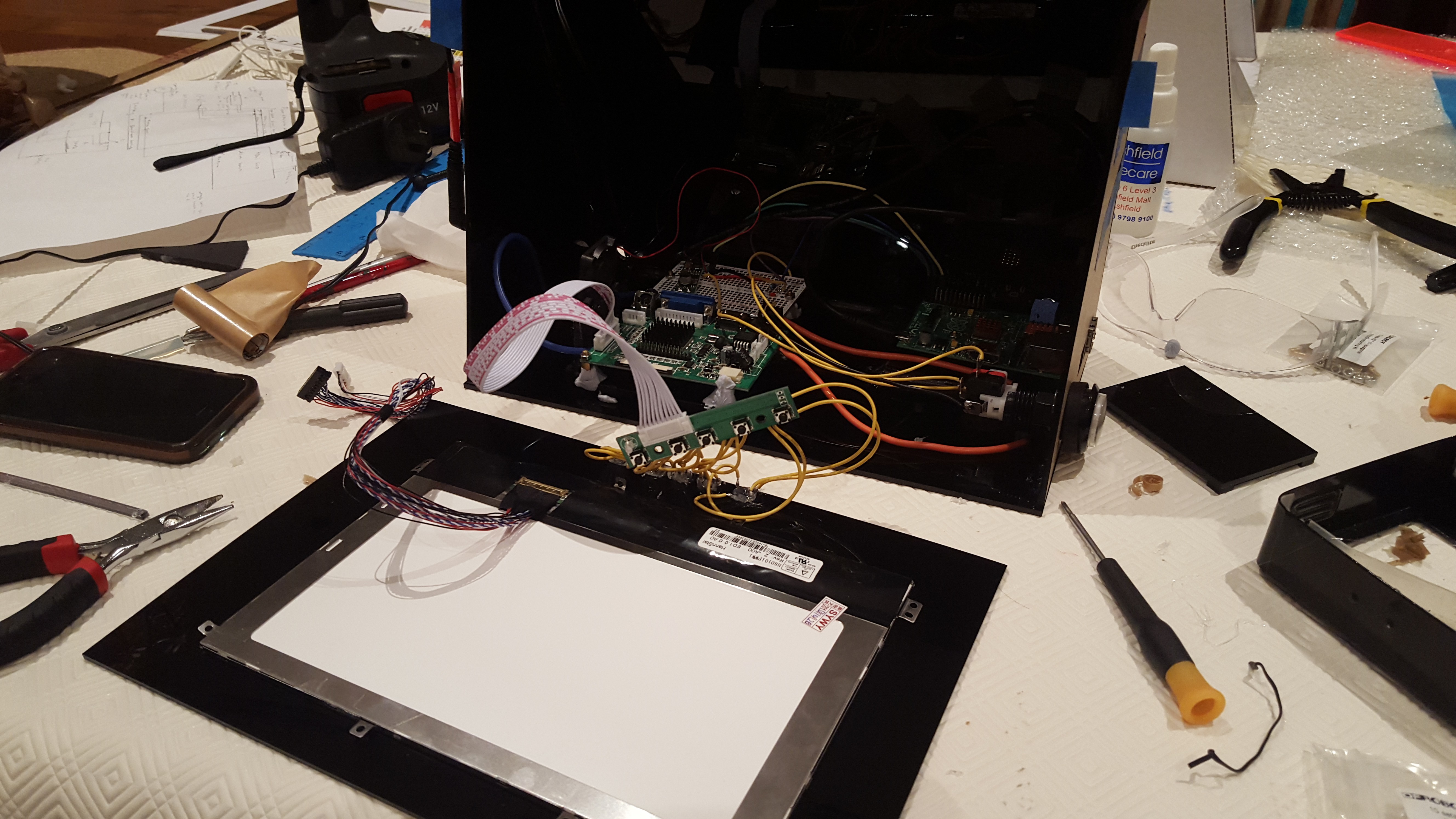 Fan installation: (the fan was pointed directly at the LCD driver IC). There was also a vent on the opposing side.
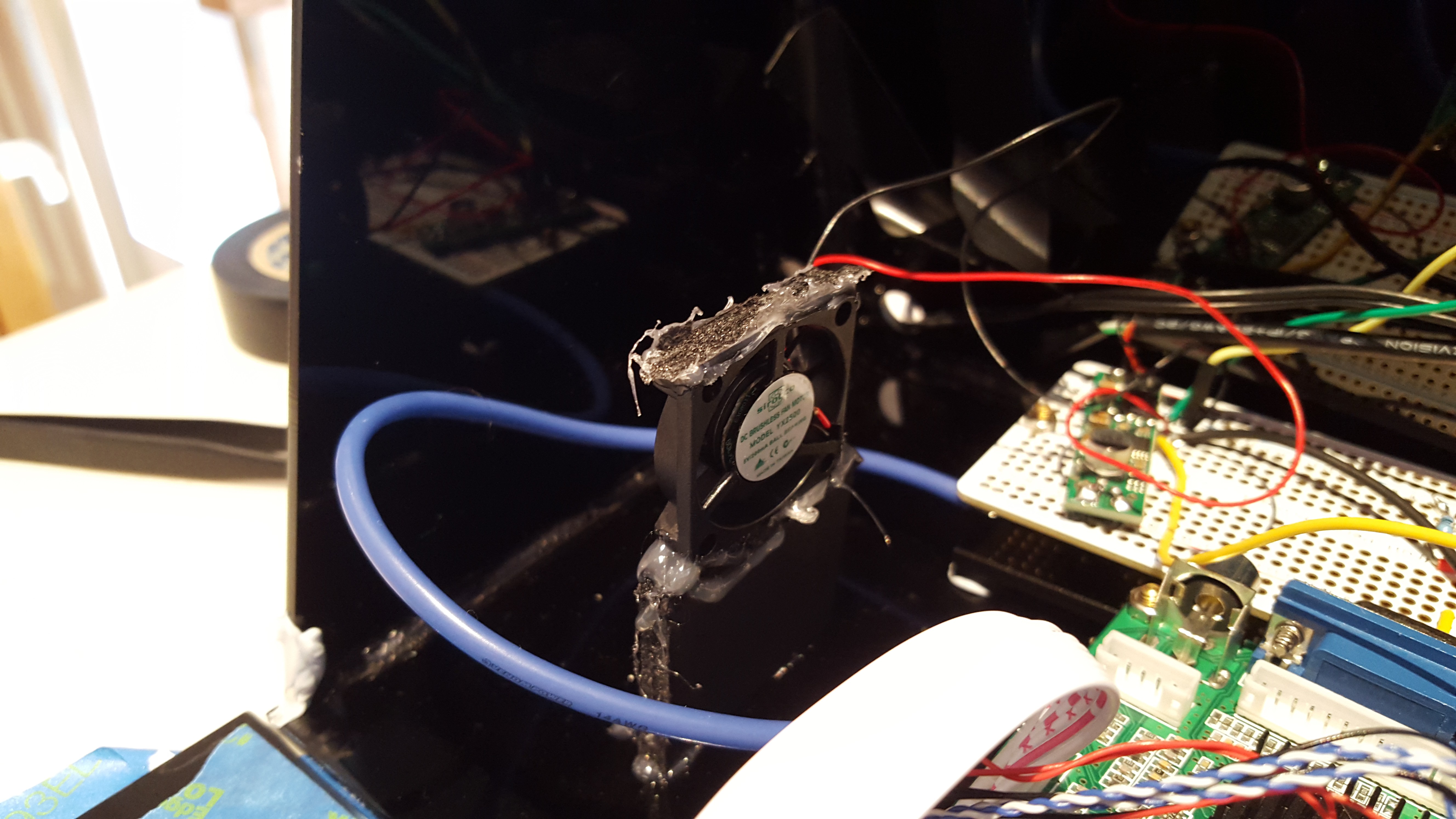
 The top panel had two magnets, this was essential as there was no other way of accessing the electronics.
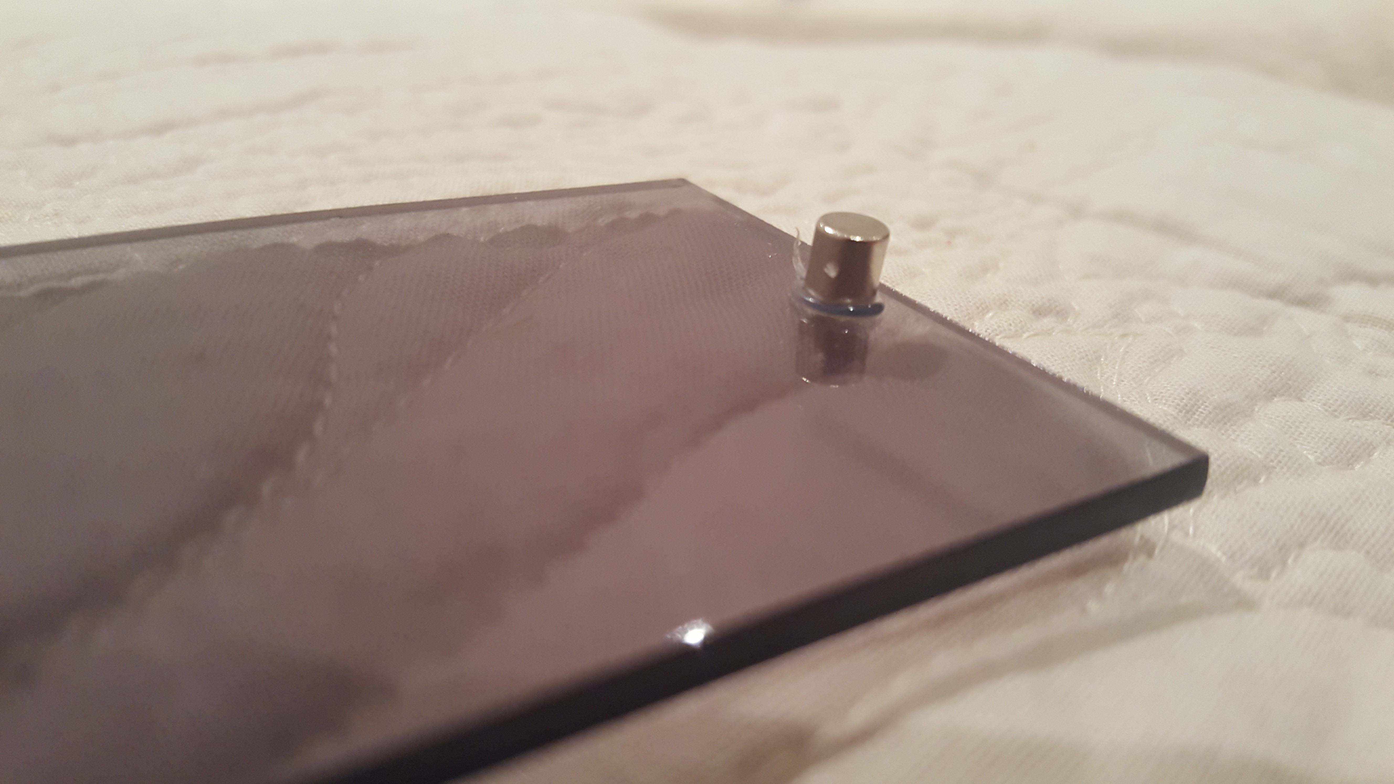 Matching interior magnet:
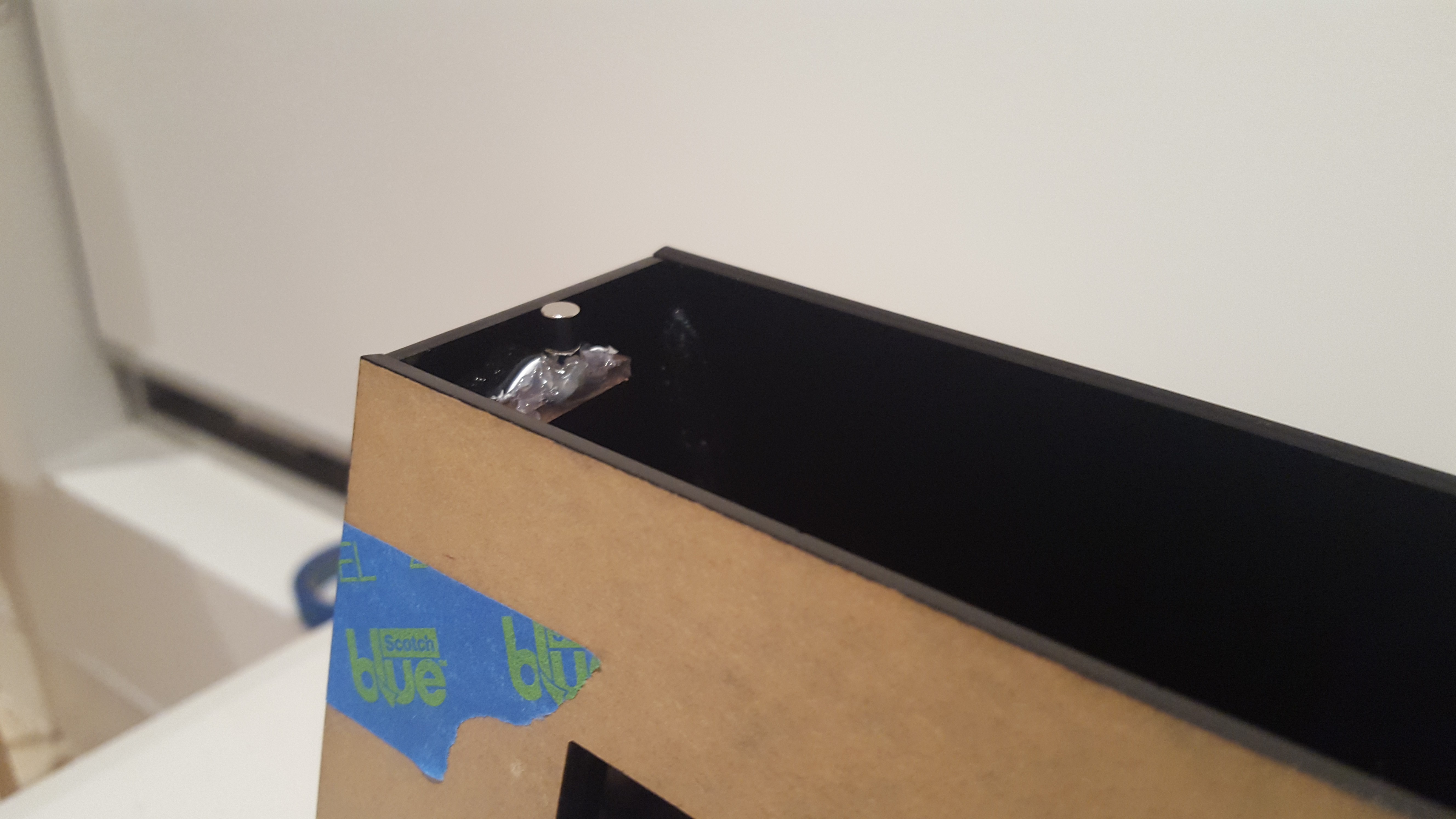 "See through" top panel:
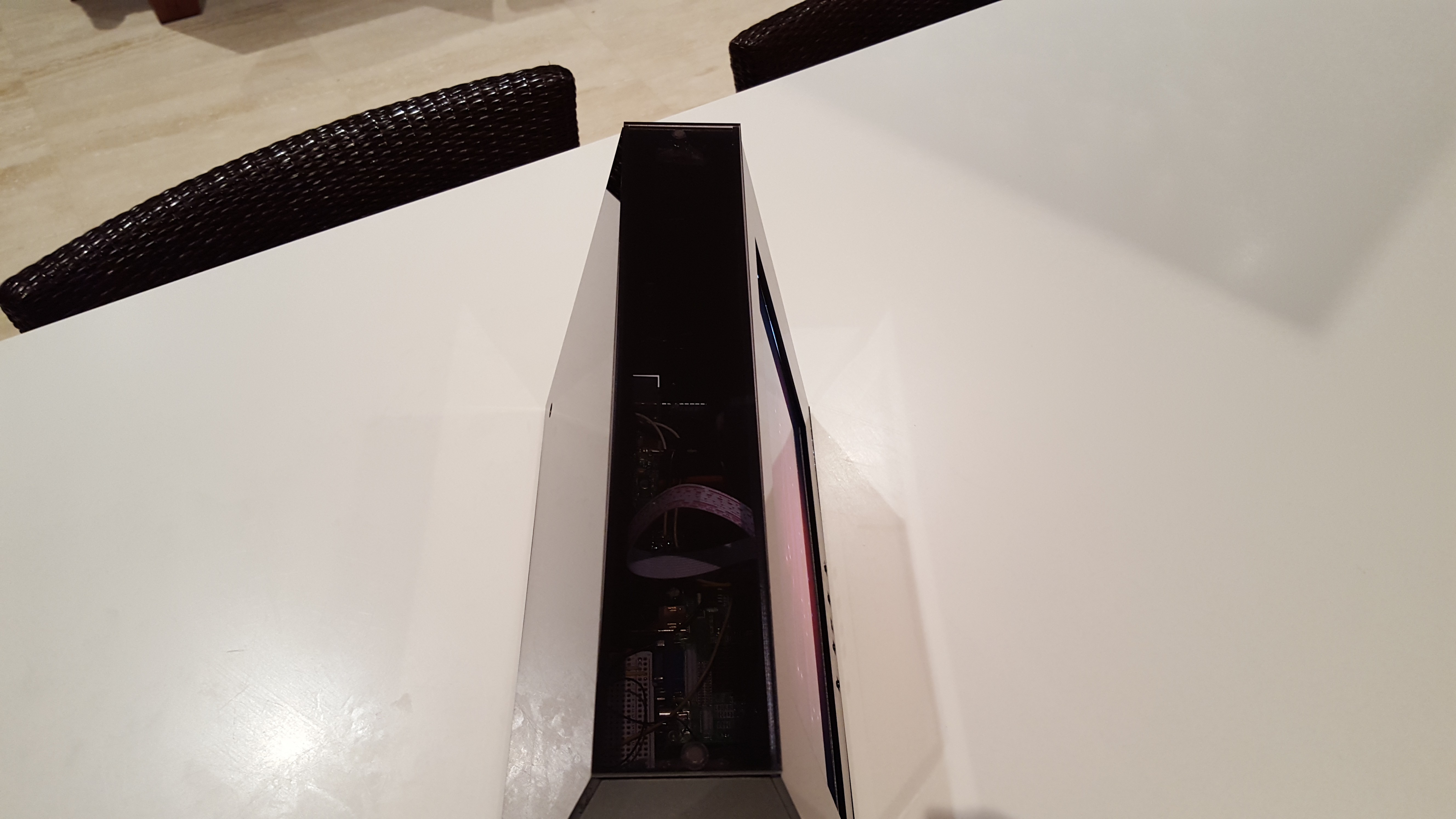 Final design:
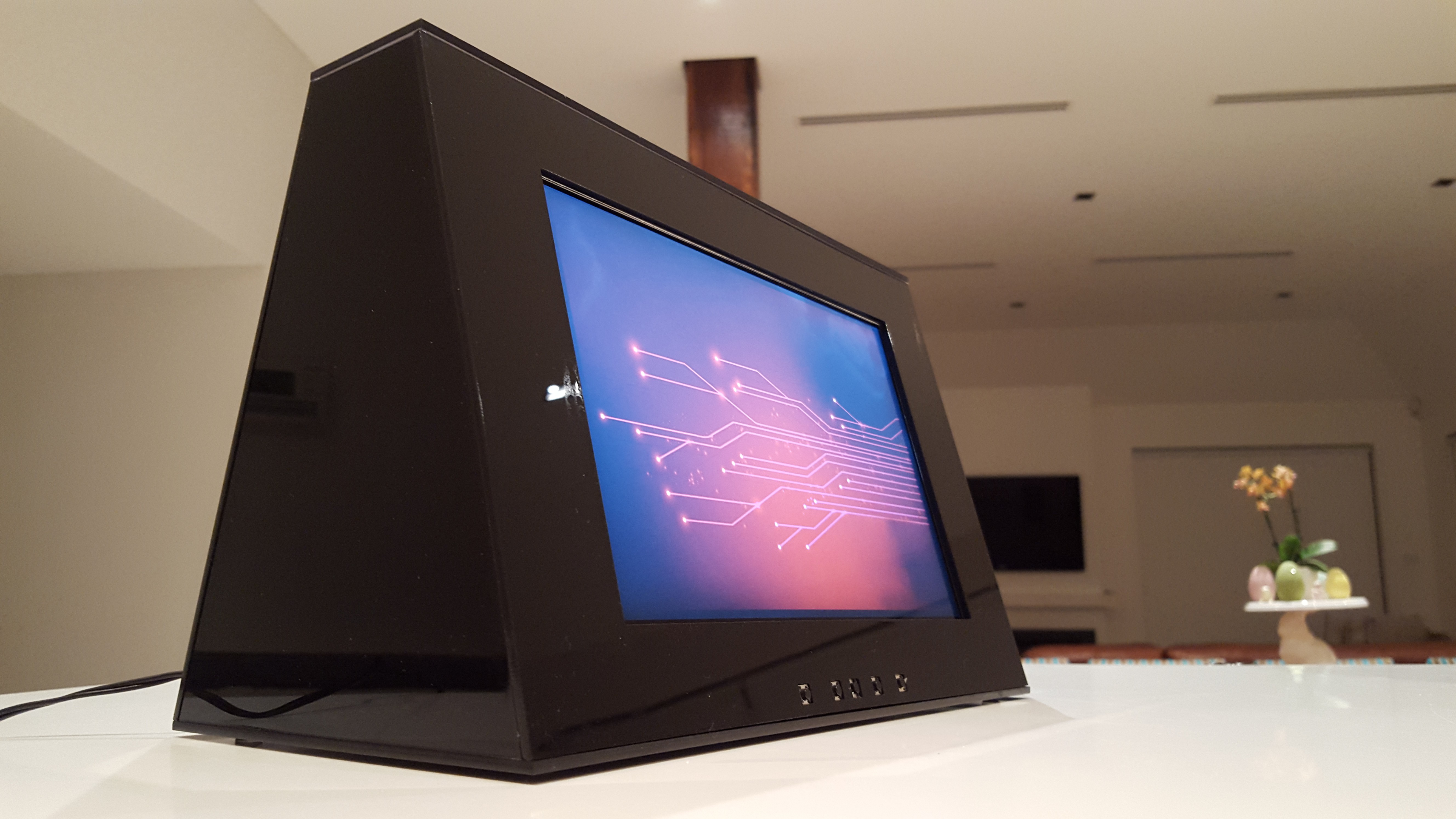
 An finally the 5V micro cooling fan. This thing actually worked wonders, it increased my Pi's performance drastically even though it was located at-least 5cm away from the Pi's CPU
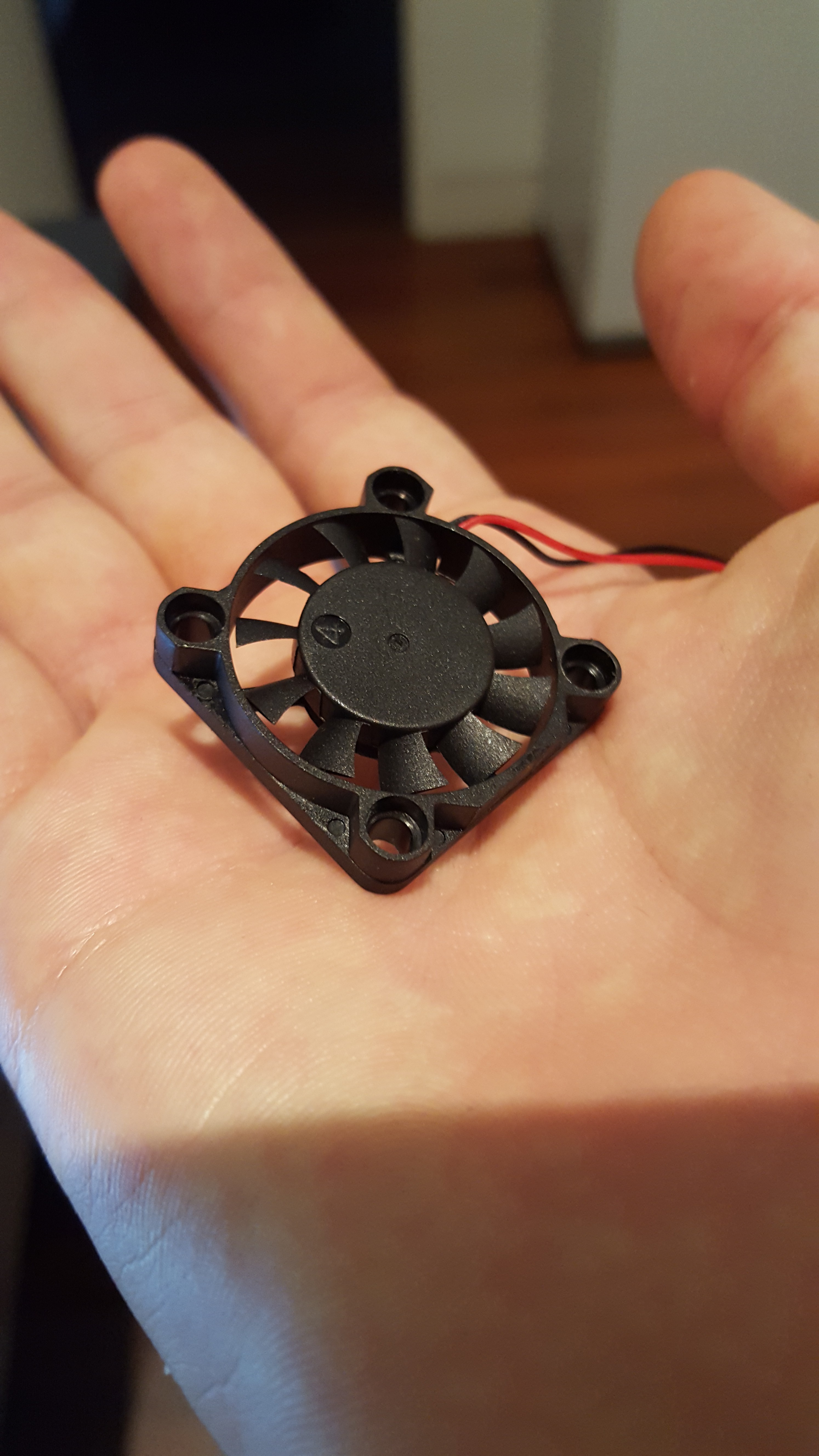

 And more....