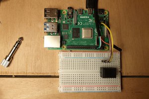
Primitive analog output device for a Raspberry Pi.
To make the experience fit your profile, pick a username and tell us what interests you.
We found and based on your interests.
analog2.cThe actual kernel module source.C Source File - 11.34 kB - 08/30/2017 at 21:00 |
|
|
IMG_20160413_154506.jpgHere's the DAC.JPEG Image - 1.47 MB - 04/13/2016 at 22:55 |
|
|
I finally got around to uploading the actual source file here. It's analog2.c because halfway through I decided I wasn't going to be sure I could get myself hooked into the interrupt controller and rewrote it to use the newer high-resolution timer system in the kernel. The final version also has runs a clock-in pin for an Analog Devices DAC chip instead of a SIP resistor ladder or homebrew R2R network. Either of those would still work, there'd just be an extra pin getting uselessly twiddled.
Once compiled and inserted a /dev/analog0 device should appear. Writing a bytes to it will fill a buffer up to 1MB which will then be clocked out to 8 sequential pins of the GPIO at 22,050hz until the final byte is reached and held. Writing one byte (on a system with no DC offset filter) should therefore just set an analog value on the DAC, while writing multiple bytes should play 8-bit mono audio (a DC offset filter is recommended in this case).
I've done the presentation, and it worked with flying colors. About the only person who's project might have been more ambitious is the guy who made a complete enough shell we couldn't think of a command it didn't have access to.
I think I'm going to hold off on posting any source code until I have a grade. Just in case the professor would get fussy about finding it online somewhere.
Also I think I've got a good application for this. It's probably one of the cheaper ways to add analog audio to a Pi Zero. Depending on how much an I2C DAC costs compared to a resistor network. Maybe a later driver can actually hooki into ALSA, although I'm sure for some applications just cramming the samples into /dev/analog0 works great.
If anyone's Interested I could put down a schematic for what version 3 of the hardware would look like.
So, I'm pretty sure it was just my non-functional test file and my DAC was working. The flaw was in my test setup. See I set up a bank of dip switches on a breadboard and ran from power to the input pins. If you're cleverer than me you may have figured it out. I needed the 0s of my resistor network to be at 0v and instead they were floating. No wonder the DAC failed that test. So if you want to build one of these a resistor ladder is probably fine, and you might even avoid having to add a voltage divider to your overly strong output like I did with my AD5330 breakout.
I fixed a bug in my write routine that made it allocate and use all space in the buffer no matter how little you wrote. Then fixed the bug I created there (it turns out get_from_user returns the number of bites NOT written). I learned to use audacity to convert files and have now played Weird Science from Oingo Boingo, or at least the first buffer-full of it, by dd'ing my raw file to /dev/analog0
It works!!!
PS. It also sounds kinda demonic if you converted the audio sample, but not the project rate in audacity and end up playing at half speed with half your samples missing.
So I unhooked the raspberry pi, and then borrowed it's ground and 3.3v and ran them through a dip switch bank into my input pins and then out to a multimeter. I did not like the results. My DAC isn't just a little nonlinear, the LSB run 1.9v and the MSB runs 2.3, and any two pins 3.3. There's no way to make a number from that little difference. There's obviously something unstated about this design and it's pissing me off. I went into panic mode attempting to find someplace I could buy a parallel DAC (not Frys as far as I could tell) in town so I could get it without shipping time. Then I vaguely remembered buying a DAC breakout from Sparkfun, but when I looked in my kit there wasn't one. I was just about to give up and went digging through the project parts box for an op-amp I bought so I could try an example circuit for R-2R DACs that used one, when I spotted the breakout board. I had put it in at the start of the project in case my own DAC was crap and I desperately needed a replacement. It's a little more complicated to operate, but it's not like I have shortage of GPIOs
I finally have a driver that doesn't crash the OS. I also have a DAC plugged into the GPIOs. I also have a demo file of an MP3 of Take On Me converted to raw unsigned mono at 22.05 khz (I think, SOX's definition of raw is creative, it may still be PCM which I don't want). DDing the demo file to the device file puts a little under a minute of file into the buffer. The device then squeals for a fraction of a second and goes silent. I haven't figured out my error yet.
I finally slogged through all my major errors and broken dependencies (most help is on making modules for the 2.6 kernel, this is 4.4!) and taught myself to use kbuild. I have a kernel module. I've also installed sox and sftp'd over some sample MP3s. I might give this a dry run and hope it just miraculously works sometime tonight.
I've been reading through the Oreilly drivers book and thought I needed to see an example kernel module to get a sense for how it's done in practice. So I went into the kernel source tree to try to find a simple character device driver I could look at. These are located in drivers/char/ in a linux source tree. A few problems quickly presented themselves:
1. Nobody comments. Okay there are comments but they're mostly the bare minimum so you know who wrote the thing and what it's supposed to be. I know you aren't supposed to comment anything obvious but these files don't even have functions labeled by purpose.
2. Most of them only look slightly like the code in the book. The coder who wrote them went and changed the name of everything to something specific and none too clear. Usually you're lucky if you can identify the init and exit functions.
There seems to be at least one exception to 2: linux/drivers/char/raw.c Sure the comments are still pretty dire, but I can actually see the structure of this one, where the file operation functions are, where their pointers are loaded into a structure and a character device gotten from the system. I'm now at least significantly less concerned that I won't figure any of this out before the deadline.
I do kinda wish I wasn't the most experienced (only) person on the team now though. Having an interactive person to explain this would be much nicer than the book.
I've got a set of links on my desktop and thought I should get them written down.
First some resources on Programming kernel modules:
http://www.tldp.org/LDP/lkmpg/2.6/html/lkmpg.html
http://www.oreilly.com/openbook/linuxdrive3/book/
The Broadcom peripherals manual, for what it's worth:
https://www.raspberrypi.org/wp-content/uploads/2012/02/BCM2835-ARM-Peripherals.pdf
Actually applied in:
http://www.pieter-jan.com/node/15 Uses the low level ports but is still running only one pin of a port at a time using bit shifts. We're going to ignore pretty much ever but shift and rotate and just write a whole 8 bits at a time.
http://xinu.mscs.mu.edu/BCM2835_System_Timer I swear I had a better link, but I can't find it now. Anyway here's some memory addresses for the system's 1mhz timer. To get a 22050hz sampling we'll be putting 45 in C3 and a pointer to our own interrupt routine in the interrupt vector location for IRQ3. This is how it would be done low level: http://xinu.mscs.mu.edu/BCM2835_Interrupt_Controller but it looks like the Kernel may have a system for it anyway: http://www.oreilly.com/openbook/linuxdrive3/book/ch10.pdf a request_irq function. It looks like it's largely function pointer based, kinda like pthread_create().
Here's some charts of various Raspberry Pi GPIO pins named by their chip pins. The order seems to be essentially random, and we might need to shift out byte a few bits if we want to keep a serial console but it looks like there's a pretty continuous block between GPIO2 and GPIO27 scattered around that connector http://www.raspberrypi-spy.co.uk/2012/06/simple-guide-to-the-rpi-gpio-header-and-pins/
Here's a header someone wrote we can canibalize for ideas: https://github.com/thenaterhood/pi-crust
A nice tool we can use to play the audio (may require root in our case) Sound Exchange AKA sox: http://sox.sourceforge.net/
And I've run out of steam for a bit so I'll leave it there.
Basic specs:
Refresh 22.050 khz
input 8-bit unsigned integers
written to character device /dev/analog0
last byte written is held until user write more bytes (pre-filtered output is fixed DC)
Audio...might be difficult.
So the thing, is ideally I want to run the update function on this at a decent audio frequency, say 22050hz. But the Linux Kernel doesn't really have features for timing with that kind of frequency. If the kernel calls your function it's once every n "jiffies" and those jiffies only come about 100 to 1000 per second. It looks like some work has been done on maybe putting a high-frequency or high-resolution timer system into the kernel, but I can't seem to find documentation or support on it in official kernels so I'm not even sure any of those would be available in a release kernel and I don't trust my knowledge of the system enough to patch things.
There is hope though, the Broadcom SOC keeps a 1mhz high-accuracy running timer and there's 4 counter registers attached to it. The problem is all I can find documentation of it from is bare-metal programming wikis, and even then 2 out of 4 counters are in use just for the GPU. So, to do audio I'd need to verify that counters 1 and 3 aren't used by the kernel, then learn how to set one of those to 45, and put an interrupt vector to my own top-half code in the right spot, and hopefully it would run.
I've never done something even remotely like any of that. The most likely of my teammates to contribute has already backed out and I haven't heard from the other in about a week. Most of the class is choosing to do stuff like multi-threaded sudoku solvers and other things that sound more impressive than they are. It appears I am going to venture all alone into the terra icognita of kernel space, on an SOC by a company who believes documentation is something that happens to other people.
Maybe it's best to just focus on the variable DC output, given the hardware already has an audio jack.
Create an account to leave a comment. Already have an account? Log In.
There's lots of attention to doing GPIO on a Pi or similar from user space, but really, if you have an OS that's a bad idea. Linux, or any Unix really, always has C (and shell too) as a first class citizen when it comes to programming languages. I don't have the excess energy to track down the sources that really let me make breakthroughs right now but there were a few. Having hardware was kinda impressive, some of the other groups essentially begged me to go after them to not show them up. I kinda made a habit of shooting-the-moon on projects by the last semester there, advantages of being both more experienced than the other undergrads and going part-time.
Hi,
I know this is tangential to the project, but it's worth knowing about the accuracy you'll get in the system.
The precision of the resistors need to be better than the smallest step of your ladder.
So using 5% resistors like you have (gold band), you'll be able to get 1/0.005 = 20 steps. That's greater than 16, so you'll be able to get 5 bits of valid data. Any more than that and your LSB will be no better than noise.
It's fun to build though, and I know your primary objective is the software, just as long as you know the physical limitations of your circuit :)
I think I was going for precision over accuracy. As long as pin 6 raises the voltage by an amount less than pin 5, and pin 7 less than 6 (or the other way around depending on significance) for simple audio I could care less if it's accurate. As it is I tore it up and switched to an Analog Device 5330 parallel DAC on a breakout when I thought it wasn't working because my sample file was wrong (and my code bugged). it turned out the DAC doesn't work when you try to control it with a dip switch bank because cut off from Vcc is floating, not ground so my diagnostic test falsely said it had less that 2 bits of precision.
On second consideration, that wouldn't guarantee that 127 is a lower voltage than 128 for example, so you're right there. However, I've got a hunch that if you sort your resistors by ascending or descending actual resistance (whichever works, I don't want to actually calculate it) and plugged them into the ladder that way you could enforce ordinality of your values, even if you can't get them linearly spaced.
"Expect the electrical engineering on this to be nearly complete crap as the team is 3 code monkeys and no real hardware people."
You know when you get it working and are demoing it, you are going to have to play "Code Monkey" by Johnathan Coulton.
Become a member to follow this project and never miss any updates
I know this project is a bit old, but this is the first project I've ever seen which shows that programming GPIO-related stuff for Linux isn't nearly as complicated as I thought. I've always wanted to get into using Linux for embedded work, but I love being in control of the CPU directly so I've almost always done all my work in C. But projects like this keep making me think I'd better learn something about this sooner or later...
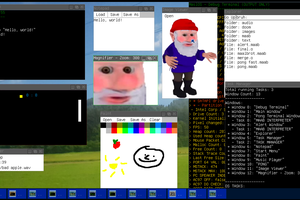
Really neat idea for a school project. I bet having hardware made your project stand out for sure! Though it's pretty crazy that someone wrote a shell...
Cheers!