Just a quick update: In the last week I've been checking and verifying the LCD / MIDI shield. I found some things I forgot to do, like marking the MIDI / serial switch, but more importantly, I found out two major design issues.
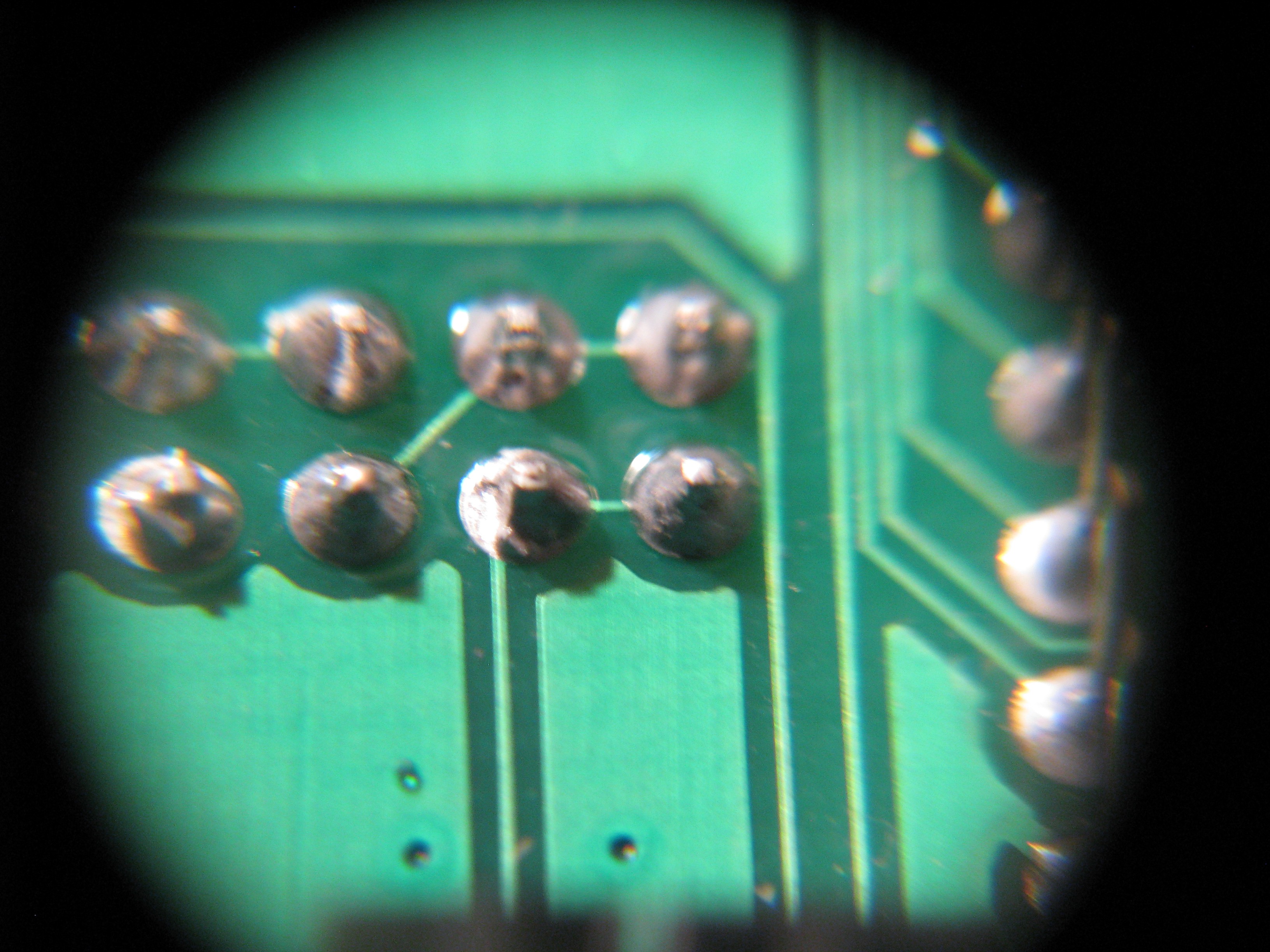
In my schematic capture I replaced and misplaced the RX / TX jumper pins. Since I'm using mocoLUFA as a basis, I wanted to be able to use either the ATmega328p OR the Atmega16U2 for serial MIDI. That way, I can transmit serial MIDI between the two ICs at a much higher rate, to free up important calculation time from the 328, and use the 16u2 for both USB MIDI and add software serial to it. The USB MIDI function uses a circular buffer, so I think it might be possible. Anyway, since I misplaced the names of the pins, when I got to PCB design I jumpered the pins from the hardware serial on the 328 to the intended soft serial on the 16u2. Somehow, when I checked the GERBERS I missed that. when I populated the board and started checking my PC couldn't find the board, and when I checked I found this:

I cut this trace, and it seems to solve this problem.
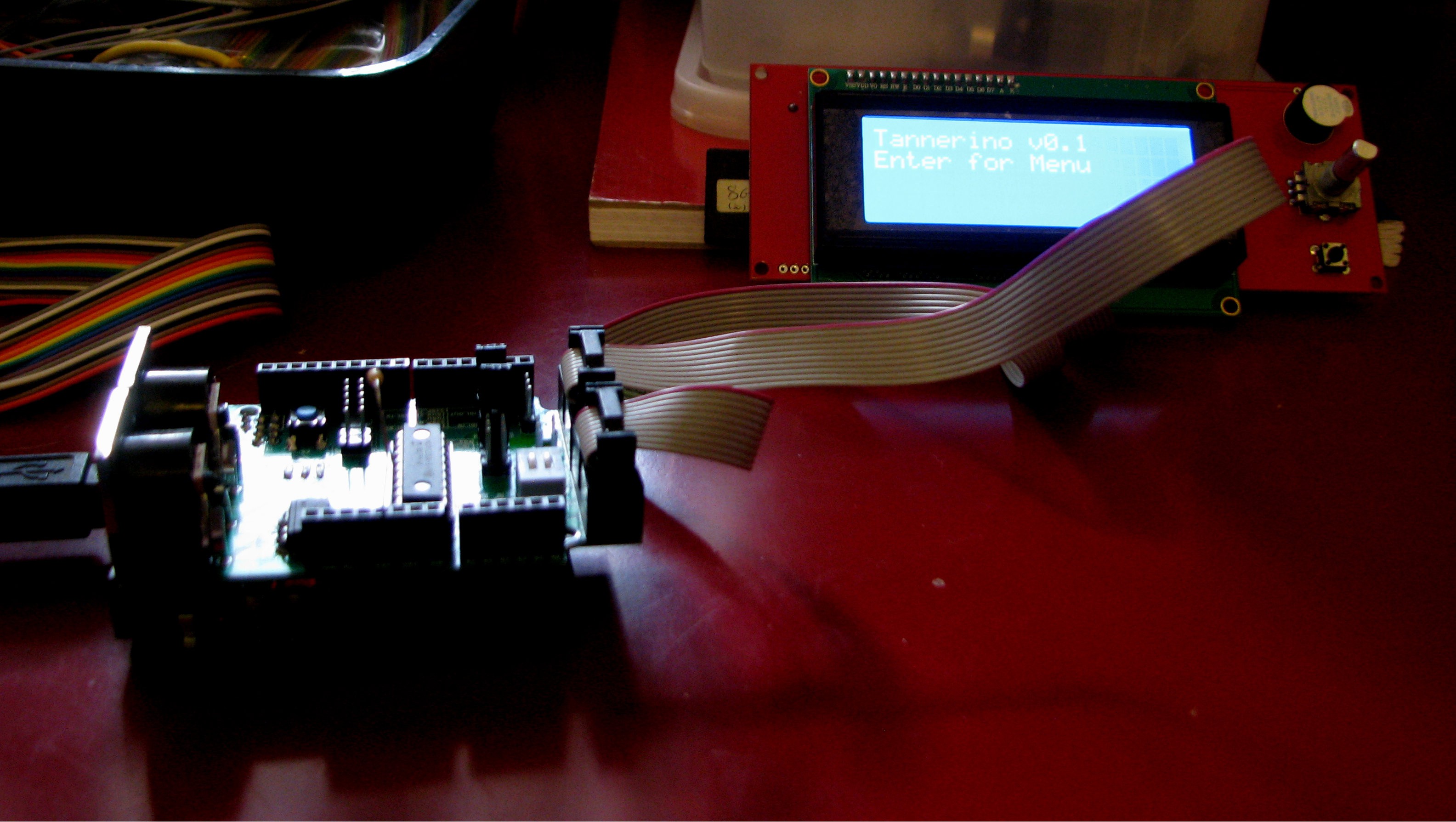
The other design mishap I found took me a longer time to find. It took me about a week (!) to find out I completely forgot to tie the reset pin high, and it seems I forgot to do that in ALL my designs. I was really banging my head to the wall trying to figure out why the design as it was did not work, as it's more-or-less a copy of the Adafruit LCD Backpack. Anyway, for the time being I'll just solder a non-smt 10k resistor hanging in mid airso I can go on. This does seem to work, as can be seen in the next picture.

There's still Serial MIDI to check, but I've checked all other peripherals of the RRD Smart Controller, and I've been working on implementing a SPI counterpart to the I2C seen in the picture (MCP23S08 instead of MCP23008).
I also found that the placement of the ribbon cable connectors is far from ideal when one wishes to combine the shields. But I'll get to that in a later update.
 uri.shani
Discussions
Become a Hackaday.io Member
Create an account to leave a comment. Already have an account? Log In.
Still verifying the boards, I'll post an update here when I have it up & running.
Are you sure? yes | no
Do you sample code for midi Buton control change part on this arduino Shield
Are you sure? yes | no