-
Waffle v2.0
02/27/2017 at 15:12 • 0 commentsAs the date of my last project log shows, I haven't been working on the Waffle project lately, for a few reasons:
- I reached the maximum memory available on the ATMega328. I'm not an efficient coder, but I realize that if I need to implement the features I want to (nice menus, file transfer interface, message saving, etc...), I'll need more memory.
- Got involved in a 2nd masters degree until late may, I've got less time to work on it...
- Less motivation altogether, other projects pop up in my head...
I'd still like to move this project forward, by restarting from scratch. I've learned the following lessons:
- SMD is not that hard to solder! As long as I stick to the pitch I've used so far, I can hand-solder it...
- Think about battery management from the start!
- Think a bit more about tolerances when designing 3D-printed cases.
- DirtyPCBs is amazing.
- PCBs with round corners are nice.
Cue the Waffle v2.0! Preliminary specs would be:
- ESP32 controller, would add Bluetooth/Wifi capabilities, along with the power of a 32-bit microcontroller! Still waiting on the software stack :)
- RFM69 radio module: they seem to use an efficient digital mode, optimized for battery usage, while staying on the 70cm band.
It'll have to wait until I make it home, get some dev boards to start designing a portable device...
-
Proof of Concept
08/04/2016 at 19:27 • 1 commentOkay! I'm back, I'm alive and kicking!
I worked on two main things: the case, and the software
Casing
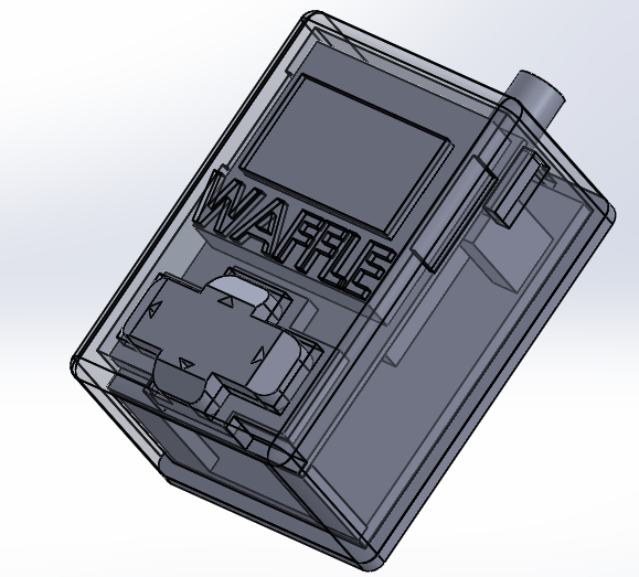
Solidworks was used for the entire process.
![]()
I first modeled the actual board, before designing the case around it. The D-Pad rests against the 5 buttons. I still have to figure something out for the central button, as it's not "pressable" yet.
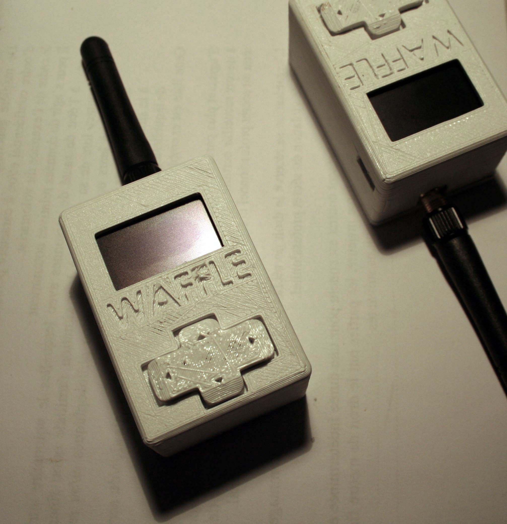
The whole thing was 3D-printed using a Fabrikator Mini (cheap 150€ printer from HobbyKing).
The board fits snugly inside the case; the screen is lined up with the opening, and the D-Pad is a perfect fit: not too loose, not too tight.
Software
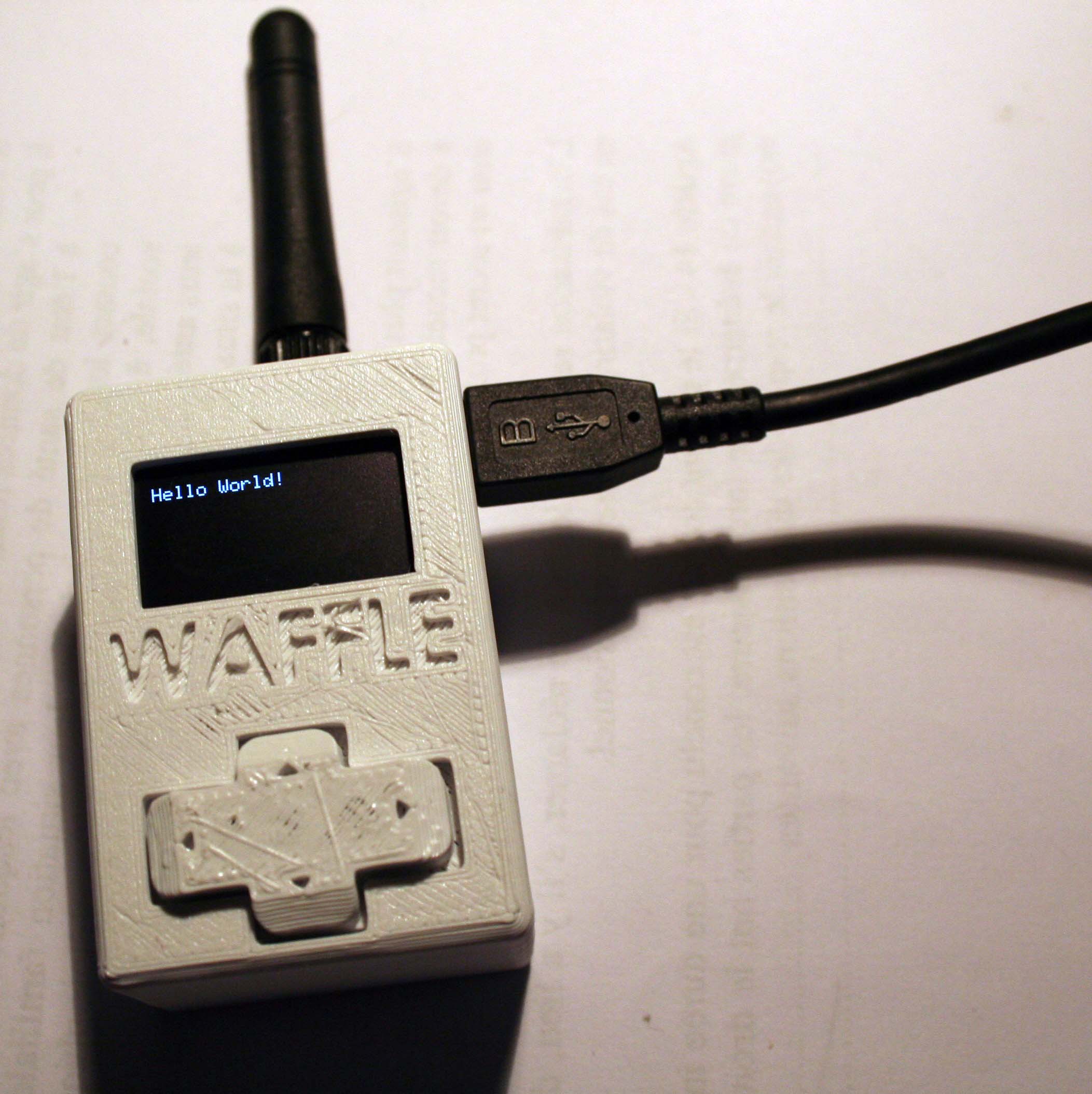
Last time, I managed to get "bits" flying between two devices. That meant having one specific RX unit, and another TX unit. This time, I can send strings either way, spit them through the serial interface and display it on the LCD!
All right, this is not real proof. I could've written a simple sketch that displays this at startup, without any radio interface. You'll have to trust me on this one. (Promised, I'll make a video showing the thing in action!... Sometime soon).
As for the user interface, I may run into some problems.
The OLED displays everything smoothly, no worries. But I will probably run out of memory before being able to implement the whole interface! I'm using the Arduino environment, with the Adadruit library. The OLED eats 1KB of RAM (the framebuffer is the most resource-hungry)! I only have one KB left to handle the CC1101 comms, serial handling, buttons scanning, battery management, ... I'm already having crashes from time to time.
So what are the solutions?
- Optimize the code the best I can: that's a good idea, as most of my code is badly written. Global variables, strings that are used as variables while they can be defined at compile-time, ... However, no matter how much I optimize the code, I feel like I'll always run into those issues when I'll start to add additional features.
- Change the microcontroller for a "better" one: by better I mean more RAM, more flash. The ATMega328 is (AFAIK) the AVR 8-bit controller with the most RAM available. I'll have to switch to another family completely. I can continue with Atmel's SAMD 32-bit series. However they look a bit pricey, I'd like this thing to be as affordable as possible. STM32 microcontrollers look promising: you can get a STM32F103 for about $1,60, with 20kB of SRAM and 64kB of flash! That's twice as much flash, 10 times as much RAM! That'll give me some headroom! The only downside is the lack of EEPROM. I can live with that. Or with an external ROM.
One of those cheapo STM32F103C8 dev boards is on its way, I'll make some tests and see how it goes! I still don't know if I'll stay with the Arduino ecosystem or if I'll go with something a bit more low-level.
So, still lots of work to do!
-
Wow, we were selected in the "Anything Goes" challenge!
06/08/2016 at 11:50 • 0 commentsWow. Just wow. Yesterday, when I loaded up my favorite website, I didn't believe it.
It's amazing to be selected for the final step of the Hackaday Prize! It's such an honor :)
The project is on hold for the following weeks as I'm finishing my exams (+master's thesis), but I'll get back on it as soon as I'm finished.
Thank you for everything, Hackaday! Thanks also to the sponsors who made this contest happen!
PS: Quick status report. Before putting this project on hold, I managed to get bits flying back and forth between two devices... Progress!
-
Small progress for the Interface
05/16/2016 at 20:06 • 0 commentsHi, just a quick log about the Computer Interface for the Waffle.
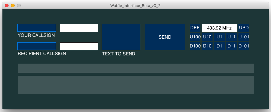
I added some functions and buttons, an most importantly, uART communication integration !! The interface now works for debugging, but it's still not finished; I need to add a settings menu for selecting the right tty/COM port, and some other minor functions.
Here's a new screenshot of the interface ^^
![]()
You can probably see the main new function : frequency selection !! This feature will only be available for licensed HAM-operators, as the only frequency that is free to use without license is 433.92MHz (in Europe, but in the US it's around 900MHz).
Right now the interface works like it should, and you can find the Processing file in the file section of this project (Waffle_interface_Beta_v0_2.pde)
Feel free to ask me any questions !!
-
First prototype
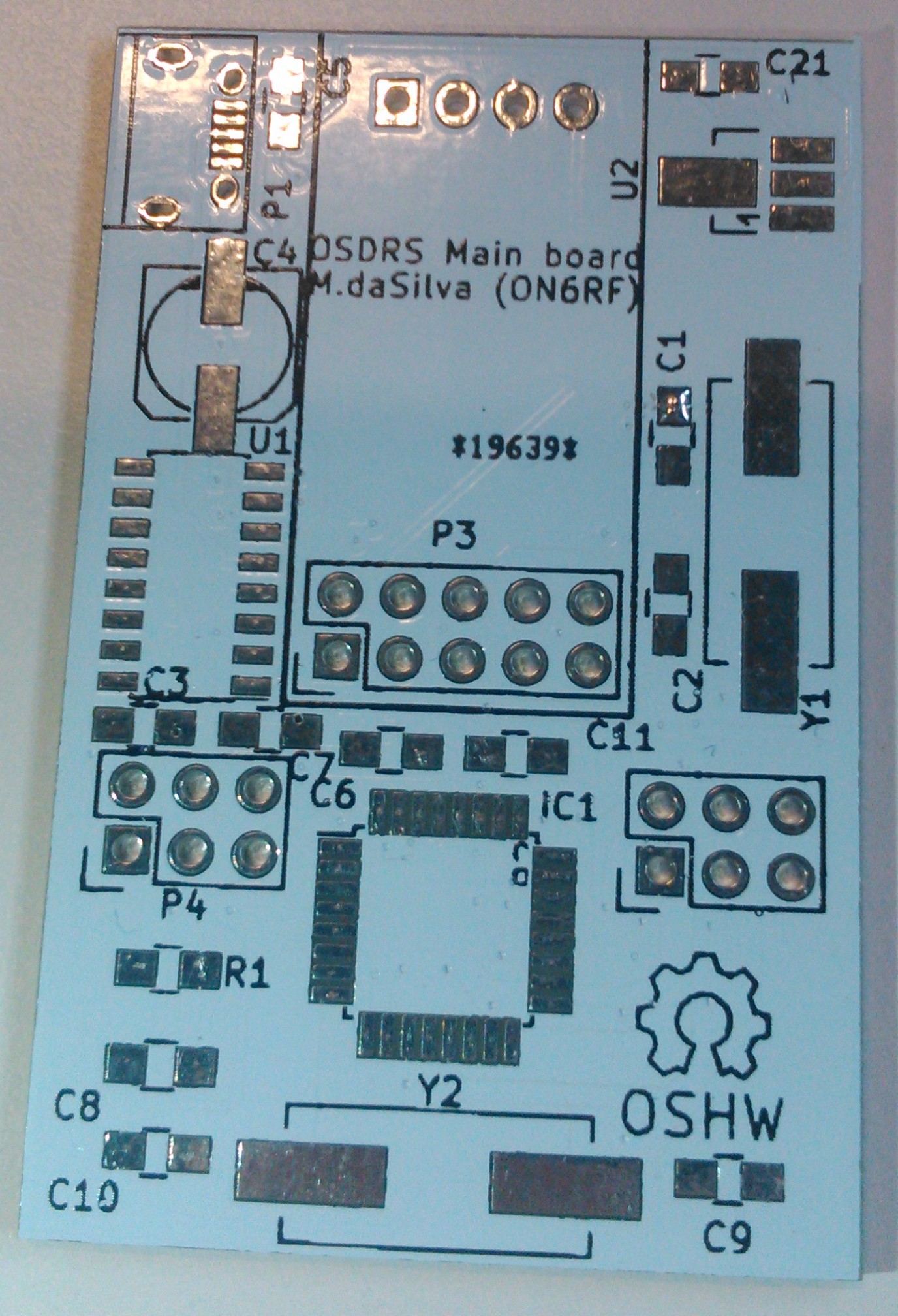
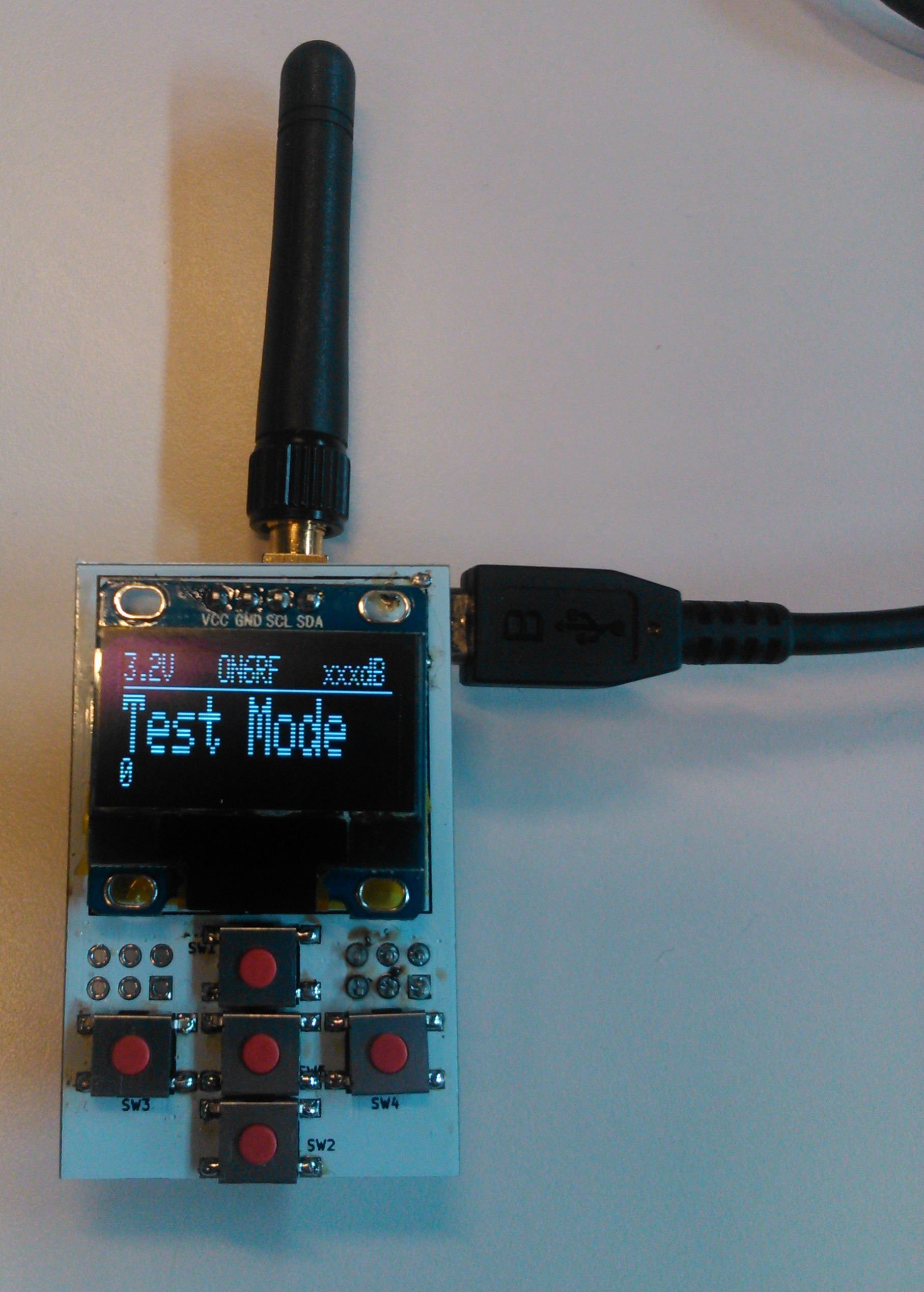
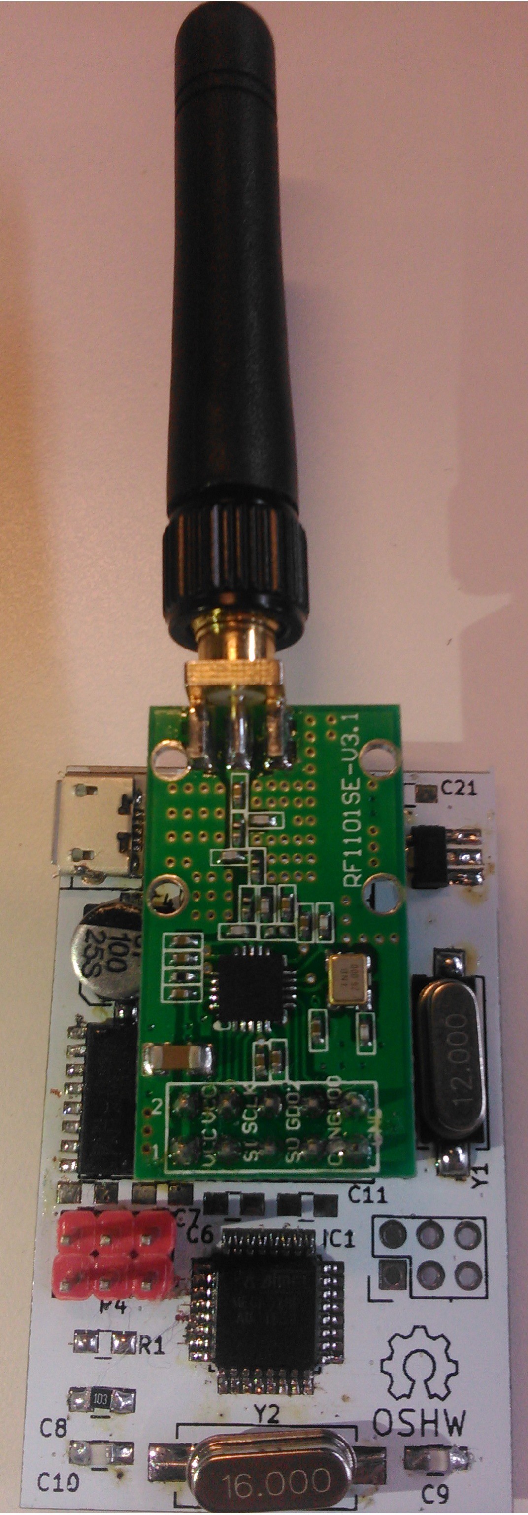
05/10/2016 at 11:12 • 0 commentsPCBs are in!
![]()
I'm still waiting for the 100nF decoupling capacitors, but I couldn't wait! I already assembled the first board.
![]()
![]()
I know, the soldering job is sloppy, my trusty Weller died on me, I had to use a plain old mains powered iron... My SMD skills aren't very good either.
The ATMega didn't get recognized by the ISP at first, some pads weren't correctly soldered. After a few tries and two different programmers, I managed to get a successful flash.
The buttons work fine, OLED doesn't have any glitches, and the USB-to-Serial converter works as planned. I'm still getting some errors during the operation of the COM port, I think it has to do with the missing decoupling caps... I'll see how it goes once they come in.
Now, off to write some software and run tests!
-
Building the dirtiest UHF antenna
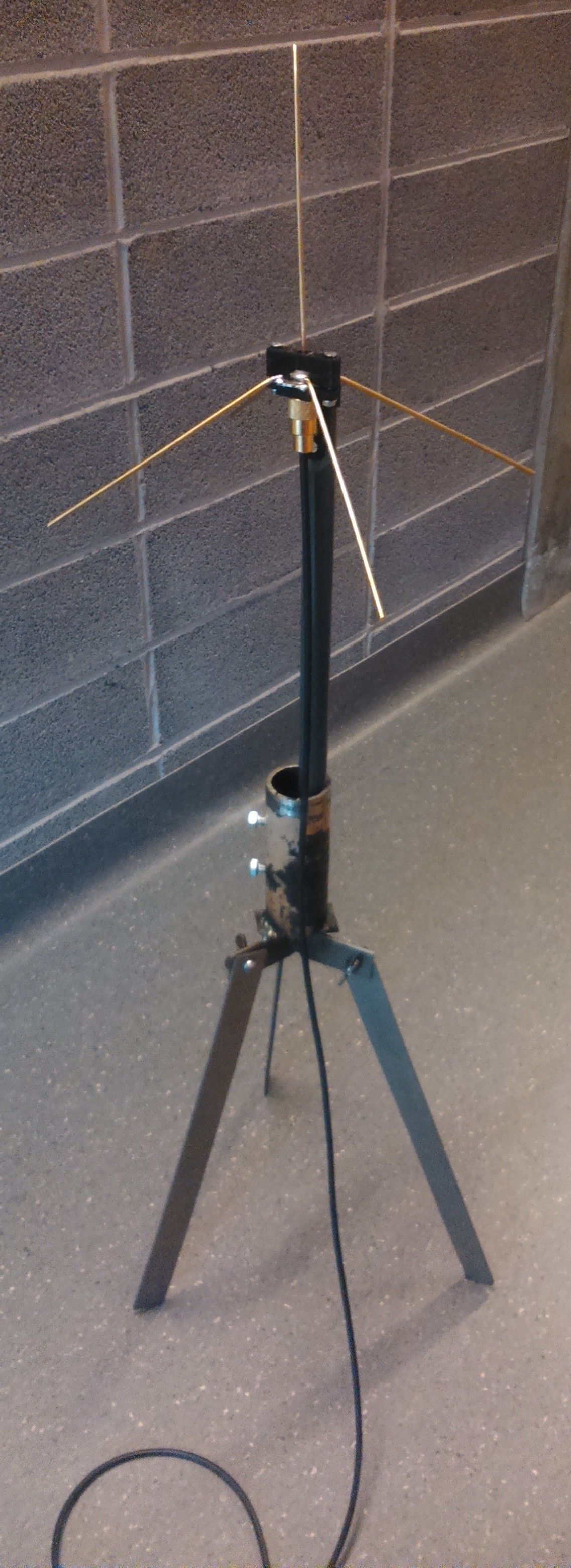
05/09/2016 at 15:17 • 0 commentsI'm still waiting for the boards to come in... In the meantime, I built an UHF antenna I could use for a base station that could withstand 20-50W.
The design is based on a plain old quarter-wave (0,164m in lenght) ground plane antenna, like this one from M0MTJ:
![Simple
1/4 Wave Ground Plane Antenna]() I used brass for the radiating element and the radials. They're a bit sturdier than copper, though I don't know how it affects performance.... It can't be worse than those stainless steel whips! The antenna was brought to a 1:1 SWR match using an antenna analyser, by trimming the antenna with a pair of pliers.
I used brass for the radiating element and the radials. They're a bit sturdier than copper, though I don't know how it affects performance.... It can't be worse than those stainless steel whips! The antenna was brought to a 1:1 SWR match using an antenna analyser, by trimming the antenna with a pair of pliers.![]()
The support is made of 3D printed PLA, as an effort to try and have as little as possible parasitic metal elements in the vincinity of the antenna. I still have to find nylon bolts and screws to lessen that impact even more.
The PLA part is attached to a nylon rod which has been milled to ensure a nice mating surface. This rod is also non-metallic as to ensure as little parasitic effects as possible.
The nylon rod will then be mounted to the actual mast, which I don't have yet.
The last part, the tripod, was built using scrap metal parts from around the shop. The three legs are held to the central body with three butterfly nuts and lock washers. A piece of pipe was welded on the top of the structure.
-
Waffle Modem Computer Interface
05/08/2016 at 17:26 • 0 commentsWhile Mano is working on the hardware, I'm working on the software side of the project.
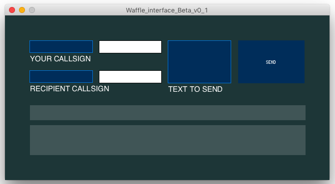
Today, I designed a raw computer interface for The Waffle using my favorite programming program, Processing. Using the basic ControlP5 GUI library, it was much easier for me to add text fields, buttons, etc.
You may ask yourself "Why in heavens name did he use Processing instead of stock Python or stock Java ?". Well, there are a few reasons why : because I'm familiar with it, because it's open-source, because it's easy to use and to implement libraries, and also because it's cross-platform, which means that I'm easily able to compile the final program as a ".app" file for OS X, ".exe" for Windows and as an Unix executable for Linux. All that just with a few clicks :)
Right now, it only works "theoretically". That means that the buttons and the text fields are working (with minor bugs, of course, thanks to Murphy), but it's still the raw interface, it doesn't send the messages over uART yet.
Here's a nice screeshot on the interface ^^
![]()
As you can see, there are 3 text inputs, 4 text outputs and one button. The two white text outputs are just echoes of the two small blue input fields, the thin grey output field is a preview of the message that will be sent over UART (with the 1st callsign, the second callsign and the message), the thick grey field will be the field where the received message will show up, and the "send" button is, well, the button that will send your message (I shall change the font here).
I may add other stuff to the interface as we need, but right now these are the fundamental functions.
If you want to look at my catastrophic code, well, maybe not catastrophic but "uncommented", you can find it at the "files" segment of this project. I will comment the final versions, but right now it is not really necessary as this is only a beta version.
-
Finding a correct name, other uses, parts coming in
04/29/2016 at 06:54 • 0 commentsFirst parts are coming in. I've sent my order 2 weeks ago... In the meantime, I started thinking about other probable uses for this system. I mean, basically, I made a small PCB with an ATMega328, a small OLED and buttons. Nothing too special, really. The radio module plugs into it, but nothing prevents me to have other uses for it!
Why not a integrated antenna analyser? I can add a simple DDS chip like the AD9850, an SWR bridge and sample the measurements through the ADC pins of the µcontroller (like this one or that one [PDF alert])! It would be teeny tiny and very useful!The whole thing can just be plugged into the header for the radio module. Plus, as the DDS chip outputs its signal directly to the connector, it can also act as a frequency generator..
I can also use it as a small voltmeter, with a divider network, some diodes for protection... Not very accurate, but still, it would be pretty interesting...
Anyway, those add-ons have to wait for the next hardware revision; I still have to find a way to make it portable. Right now it depends on the USB supply to run, not a convenient thing to have if you want to put it in your pocket...
Also found a name for my project: Waffle. Why Waffle you may ask? Well, I like waffles. A friend found a matching abbreviation for it: Wireless And Free Format Lite Emitter. Feel free to use yours! I'll just stick with "Waffle" :)
-
PCBs
04/25/2016 at 15:11 • 0 commentsJust ordered the PCBs from DirtyPCBS!
![http://dirtypcbs.com/order_images/974c28c5b78e50cb8447750d687c1398-19639_top.png]()
![http://dirtypcbs.com/order_images/974c28c5b78e50cb8447750d687c1398-19639_bottom.png]()
I chose to have it in white. I kinda like the looks of it! The "back" side is reversed, I think it's a small bug of DirtyPCBs, I'm not worrying too much, it looked fine on other Gerber viewers.
The components are also on their way, I hope they won't take too long...
-
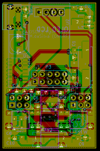
Main board design
04/23/2016 at 07:47 • 0 commentsSooo... First thing I need to design is the main board. It contains:
- The ATMega328, with the appropriate crystals;
- A USB to serial converter;
- The actual radio module;
- A small display;
- Buttons!
- Supporting hardware for all this stuff (regulators, decoupling caps, crystals, etc.).
It's your average Arduino-thingy board, the design process is quite straightforward.
![V1.0]()
Small note regarding the RF part: I added all the supporting hardware for the CC1101 on this schematic: the balun system plus all the filters for the 433MHz band. However, I am not going to add this section to the first version: it is my first SMD design, I don't want to add the complexity of RF to this design for now (plus the QFN-20 package is tiny!). I'll use some ready-made modules that will be soldered though a header for now.
I added 6-pin header for the future PA board; I brought out two IO pins from the µcontroller, 5V and 3.3V power, and ground. RF won't be going through there, I'd rather connect the PA and the radio module through some piece of coax.
![]()
I tried to fit everything onto a 5x3cm board. Phew. Lots of vias, and some traces take a long way to connect one point to another; I'm a bit worried about the USB lines and the crystal for the USB to serial converter, they seem a bit long to me.
Meh, I'll send it to the fabhouse and see how it goes! Worst case scenario, I'll learn something along the way :)
Waffle: a pocket-sized digital radio system
µController, CC1101 module and LCD forming a small communication device. Other probable uses in the near future.
 M.daSilva
 I used brass for the radiating element and the radials. They're a bit sturdier than copper, though I don't know how it affects performance.... It can't be worse than those stainless steel whips! The antenna was brought to a 1:1 SWR match using an antenna analyser, by trimming the antenna with a pair of pliers.