Tom Meehan
-
Configuring the TGAM1 Board for 57600 baud (raw data)
10/03/2016 at 04:12 • 0 commentsNeed .png of top of board with white background
Configuring the TGAM1 board for raw EEG data (57600 baud) - using the Hardware method
- The default output baud rate for TGAM1 boards (at least the ones taken out of Mindflex and Force Trainer headsets) is 9600 baud (this only allows you to capture data for the default frequency bands once per second).
- To use these cheap headsets with apps made to work with "Think Gear" headsets - we need to change the communication rate to 57600 baud. There are 2 methods to achieve this:
- One way involves programming the TGAM1 board over Bluetooth - if you look through the links at the end of this post you'll find ways of doing this. I did not do it this way, instead I chose the second method.
- The second way involves removing
a single SMD (surface mount) resistor (pull-down resistor) and
adding a different resistor going from the same area and then over
to positive connection of the power supply on the TGAM1 board
(pull-up resistor).
- To do this you'll only need:
- Basic soldering iron
- 1 x 10k 1/8th watt resistor
- Heat shrink tubing to insulate the resistor
- To do this you'll only need:
- Step 1: Remove SMD
Resistor (surface mount resistor, it a little rectangle on the top
of the board.
- The SMD resistor can be removed by heating up the pad with a soldering iron and pulling it off with tweezers (or, if you are brave - snap it off with needle nose pliers).
- Step 2 -
Solder in the 10k through hole -(meaning is has wires) resistor.
- the 10k resistor goes from the spot marked B1 on the board and goes over to the positive power connection (refer to the labeled picture at the top of this post)
-
Configuring the HC-06 Bluetooth Serial Module
10/03/2016 at 04:06 • 2 commentsSome REALLY BASIC! Background on Bluetooth CommunicationBeing very, very new to working with Bluetooth, myself, I decided to include some additional information so that others can hopefully avoid making the same mistakes that I've made:
Slave vs Master- Master is the device at the center of a Bluetooth network (in this case – your phone, tablet or computer)
- a Master can pair with multiple Slave devices
- a Master can pair with multiple Slave devices
- Slaves send and receive data only to or from the Master (in this
case – the MindFlex headset, you could, conceivably, pair multiple
headsets to one Master device)
- a Slave can only be paired to 1 Master at a time
- a Slave can only be paired to 1 Master at a time
Pairing
- Bonds Slave device to Master device
- After pairing devices automatically connect when they are both powered on and close enough
- uses authentication data saved on the 2 devices
- uses authentication data saved on the 2 devices
Profiles (devices need to support the same profile to communicate - "communication profiles") – this is not an exhaustive list
- HSP -head set profile
- HFP – hands free profile
- HID – human interface device (generally a keyboard, mouse, etc.)
- SPP – serial port profile (this is what we need for communication)
- A2DP – advanced audio distribution profile (streaming audio data to speakers, etc)
- AVRCP – A/V remote control profile (Bluetooth remote for TV, etc.)
- A little note on profiles and their importance: I have an older android smartphone (Bluetooth and WiFi capable), an IPhone 5 and a Kindle Fire. It turns out that none of them support the Bluetooth Serial Port Profile and as a result the only way I can use the Bluetooth connection is with my laptop and a Bluetooth USB dongle. So, if you are planning to use this with a specific device make sure to check if it supports SPP (Serial Port Profile) Bluetooth Profile. If your device does not Bluetooth SPP (turned out that none of the devices I have support it) then you'll need a USB Bluetooth dongle that supports SPP (around $5).
Bluetooth Modules (again: really basic!)Be sure to ca
- The first modules I purchased were actually just back planes (essentially just the breakout board without the module – read descriptions very carefully – not a costly mistake but annoying and time consuming).
- The next module was a Master – (projects I looked at never seemed to mention if I needed a Master or Slave module... well it turns out I needed a Slave module, of cour.
- Slave Module!
You can find these on the datasheets for the Bluetooth Serial Modules (you can find them online - none of the ones I ordered included the datasheet). AT commands apply to both the HC-05 and HC-06 boards. These are the ones we need to setup the HC-06 breakout:
- AT pings the device (response back “OK”over serial)
- AT+PINxxx
- AT+NAMExxx
- AT+BAUD4 (sets baudrate to 9600 – default rate)
- AT+BAUD7 (sets baudrate to 57600)
Setting up the HC-06 Bluetooth Slave Module (SPP – Serial Port Profile)
Configuring the Bluetooth Slave Module for 57600 baud rate (most modules seem to be configured for 9600 baud rate as the default setting) **This step should be done with the Bluetooth Module alone (not connected to the TGAM1 board)**
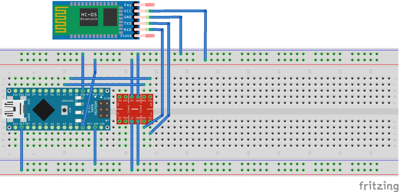
Wiring the HC-06 and configuring using an Arduino
- The logic level shifter is not optional - these modules use 3.3v logic (RX/TX lines must be 3.3v)
![]() Bluetooth TX goes thru level shifter to Arduino TX (Pin 3). Bluetooth RX goes thru level shifter to Arduino RX (Pin 4).
Bluetooth TX goes thru level shifter to Arduino TX (Pin 3). Bluetooth RX goes thru level shifter to Arduino RX (Pin 4).Arduino Code:
/*
HC-06 Bluetooth simple setup sketch

*** Important. If you change the HC-06 baud rate, you must change the "myserial" baud to match what was just set.
* Steps:

Changing default 9600 baud to 57600 baud needed to communicate raw data from TGAM1 chip
1) uncomment (remove the double backslash) the line:  //btSerial.begin(9600);
2) uncomment the line:  //btSerial.print("AT+BAUD7"); // Set baudrate to 57600
3) run the sketch.  This will set the baud to 57600.  However, you may not see the response OK.
4) comment out (add double backslash back) the line btSerial.begin(9600);
5) uncomment the line //btSerial.begin(57600); and compile and load the sketch again - this sets "btSerial" to the new setting.
6) open the serial monitor from the Arduino IDE - this will restart the sketch.  Be sure that the communication speed
on the serial monitor is set to 57600.  If all is well you should see a secomd line after "Hello Bluetooth"
that will show the BT module responding to the change.
7) you can verify the connection by typing "AT" in the serial terminal and sending.  You should recieve "OK" back


*/
#include <SoftwareSerial.h>

SoftwareSerial btSerial(3, 4);      // RX, TX

void setup()
{
pinMode(3, INPUT_PULLUP);
//Serial.begin(9600);                 //Step one - Comment out after setting tp 57600
Serial.begin(57600);
Serial.println("Hello Bluetooth");  //prints in serial monitor when it is opened
//btSerial.begin(9600);               //Step one - Comment out after setting to 57600
btSerial.begin(57600);            //Un-Comment - after setting baud to 57600
//delay(1000);
//btSerial.println("AT+RESET");
delay(1000);

btSerial.print("AT");               //pings the HC-06 - should send back OK to serial monitor
delay(1000);
btSerial.print("AT+PIN1234");       //Set pin to 1234
delay(1000);
btSerial.print("AT+NAMEBrain");   //Set the name to Brain
//delay(1000);
//btSerial.print("AT+BAUD4");       //Set baudrate to 9600
btSerial.print("AT+BAUD7");       //Set baudrate to 57600
Serial.write(btSerial.read());
delay(1000);
}

void loop()                         //run over and over
{
if (btSerial.available())
Serial.write(btSerial.read());
//Serial.println(btSerial.read());
if (Serial.available())
btSerial.write(Serial.read());
}
I'll post this code in the Documents Section and on the GitHub Repository.If you followed the directions in the Arduino code (above) then your module is ready to connect to the TGAM1 board.
- Master is the device at the center of a Bluetooth network (in this case – your phone, tablet or computer)
-
Converting a Mindflex to a MindWaveMobile Headset
10/03/2016 at 02:07 • 2 commentsThis basically involves adding a Bluetooth serial transmitter (and configuring it) to the Mindflex Headset and changing some components on the TGAM1 board (the board that acquires the EEG data).
This ended up being a bit of an adventure – even after a good deal of research (reading datasheet's very carefully) and reviewing other peoples tutorials of similar hacks. In the end, it took about a week of part time research on components, Bluetooth (profiles, module boards, communication protocols), TGAM1 board (communication protocols, identifying board connection points, hardware settings etc.). Presently, I have a fully functional headset that is recognized by Neurosky's MindWaveMobile software as a MindWave Mobile Headset.
Hardware:- Mindflex Headset ($10-20 on ebay)
- HC-06
Bluetooth
Slave Module (that communicates
with Serial Port Profile (SPP))
- these are between $5-10 on Amazon or Ebay (cheaper in quantity, or if you are willing to wait, from China)
- should be able to use an HC-05 also (connections and configurations a little different – HC-05 can be configured either as a Master or a Slave module – unlike HC-06 which is only one or the other)
- I'm a noob concerning Bluetooth: protocols, host modes, etc.
- 10k resistor (pull up to set TGAM board to 57600 baud, ¼ or 1/8 watt)
- Hookup wire
- Soldering iron (and solder, of course)
- Multi-Tester/VOMeter (non-essential - mainly to verify connections)
- Magnifier (non-essential - to see TGAM1 board pins and labels clearly)
- 5V to 3.3V Level Shifter (essential if using an Arduino board to set up the Bluetooth module, non-essential otherwise)
-
Arduino Board with USB
connection
- Software Serial sketch
- This is what I ended up using
and it worked fine – though you do need to upload the sketch a
few times:
- Change baud rate of module
- change software serial baud rate – reload
- etc.
- Change baud rate of module
- This is what I ended up using
and it worked fine – though you do need to upload the sketch a
few times:
- Software Serial sketch
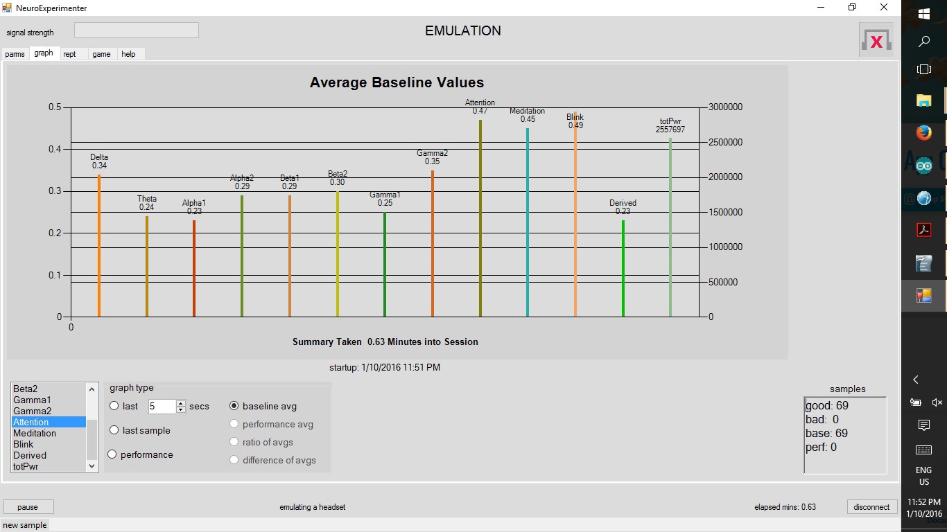
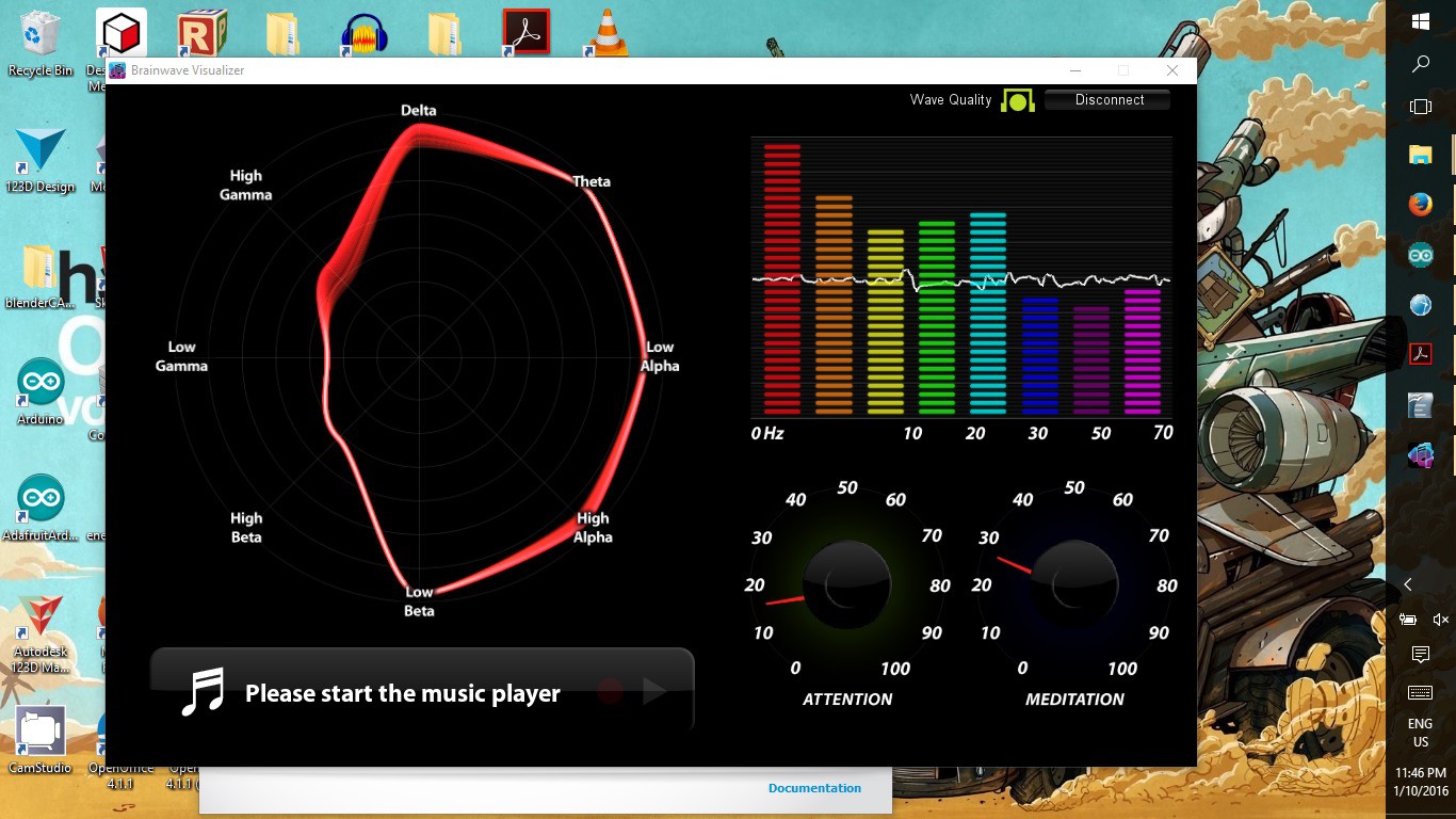
Here are a couple of screen shots of the headset working with a couple of applications:
![]()
![]()
Next up -
- Setting up TGAM1 board for raw data communication.
- How to Set Up Bluetooth Board to transmit.
- Connecting HC-06 Bluetooth board to the TGAM1 Board.
-
Neurofeedback References
09/14/2016 at 05:04 • 0 commentsDirect links to full text when possible, pubmed link, web link, or at least citation.
- Neurosky http://neurosky.com/ http://developer.neurosky.com/ (links to many different hacks)
- http://neurosky.com/biosensors/eeg-sensor/
- http://store.neurosky.com/pages/mindwave
- http://store.neurosky.com/collections/apps
- Development Tools for PC/Mac
- Brainwave starter kit
- http://developer.neurosky.com/docs/doku.php?id=mindwavemobile
- Mindflex/Mindwave Mobile Core
- ThinkGear Connector
- Developer Software
- Mindflex/Mindwave Mobile Core
- http://developer.neurosky.com/docs/doku.php?id=mindwavemobile
- http://neurosky.com/biosensors/eeg-sensor/
- NeuroExperimenter (application) – development site https://sites.google.com/site/fredm/neuroexperimenter
- TGAM1 DataSheet http://www.docfoc.com/t-gam-sales-sheet-20111004
- http://www.instructables.com/id/AT-command-mode-of-HC-05-Bluetooth-module/
- Neurosky http://neurosky.com/ http://developer.neurosky.com/ (links to many different hacks)
-
A functioning JavaFX Media Player - FINALLY
09/14/2016 at 05:01 • 0 commentsJava coding has been difficult for me but after working with MPLABX to develop code for PIC micro-controllers (MPLABX is built on Netbeans - just like the Arduino IDE was developed from Processing). Anyway, all the trials I've had in PIC programming have paid off for me in understanding Java coding using the NetBeans IDE. As a result, in just a morning of work I finally got a basic video player functional using JavaFX in NetBeans.
Fairly simple code, I'll post it up in the morning tomorrow.
-
Continuing Java NeuroFeedback Development
09/11/2016 at 01:49 • 0 commentsI've been digging into existing code for parsing the serial data from the TGAM1 board, mainly the open source Brainflex Project, instead of the ThinkGear Connector from Neurosky. A more direct link to the download release page: BrainFlex02 (I'm using the research release).
After having issues with the compiled .jar file (Brainflex001.jar) – not connecting to headset – I decided to build the .jar file for Brainflex02 (the research release). I've been working a lot with the NetBeans IDE, for this project and with Microchips MPLABX, which is built on the NetBeans IDE. Even so, I am still learning all the little in's and out's needed to effectively use it.
To build an executable .jar file from the source code using NetBeans: After opening NetBeans I clicked File → New Project and selected Java → JavaApplication. I named the project “BrainFlex2Build”. After creating the project I imported the unzipped files from the github repository, that I downloaded.
After importing the source files I immediately saw errors flagged, even before building the project. I still attempted to build the project, just so that I could see what the specific errors were. The build errors turned out to be the result of missing libraries – specifically the jSSC (Java Simple Serial Connector) library and the Apache.org Math3 library. I was able to find both of these with a simple search but couldn't figure out how to add them to NetBeans so that the functions would be included in the build. Lucky for me I came across the following article, including videos, by Andr.oid Eric: Prepare jSSC download and add library
While there is no voice over on these videos, they are short and quite clear as to how to add libraries to NetBeans and added the libraries to the properties of the project file (so they are included in the compiled code).
Quick comment: Switching from a plain dry electrode (the one on the MindFlex headset) to a 'wet' electrode (using conductive electrode paste) definitely improves the signal. I am curious: does using 'wet' electrodes allow from longer electrode cables?
-
Software Development Slow But Promising
07/18/2016 at 06:41 • 0 commentsHardware development has been pretty straightforward - everything is working perfectly on that front.
Software development is a bit slower due to having to learn Java programming. I am steadily learning it by working on it every day. Also, I've got the logic for the base program clearly worked out.
I don't have much to post but the project is far from dead or abandoned - I'm determined to finish the basic software platform so that is is usable and expansible.
-
Everything keeps changing...
06/07/2016 at 04:48 • 0 commentsMy initial hardware design involved pulling the TGAM1 board out of the MindFlex Headset, placing it in a separate enclosure with a Bluetooth transmitter and using a separate power supply (with batteries and voltage regulator). While this was ended up being perfectly functional, I found there were other issues – mainly the reach for the EEG electrode. The lead wire is limited to a max length of 12” (according to the data-sheet for the TGAM1 board – the original lead wire was only about 3” long with a fixed electrode). With a max length of 12 inches, the TGAM1 board needs to be fairly close to the the head to allow the EEG electrode to reach most of the scalp.
The main limitations I see with the MindFlex headset are:
- Electrode placement is fixed. (No choice on placement)
- Comfort, EEG electrode contact uncomfortable after short period of time.
- Poor conduction, EEG electrode is just metal to skin contact (simple dry electrode) – no electrolyte used to improve signal conduction and no adhesive used to ensure good contact.
Electrode Specs (per the TGAM1 Datasheet, page 3):
- Maximum surface area of ~150mm2 (but less surface area is optimal)
- Ag/AgCl, Stainless Steel, Gold, or/and Silver (both solid and plated material works)
- EEG electrode located above the left or right eye on the forehead
- Ground and reference electrodes located behind the ear or at the earlobe
- Have enough pressure to prevent movement, with a minimum of 0.8 PSI
- Length of less than 12 inches, the longer the higher the susceptibility to noise
- Shielding (not necessary for the ground)
- Thinner than AWG28
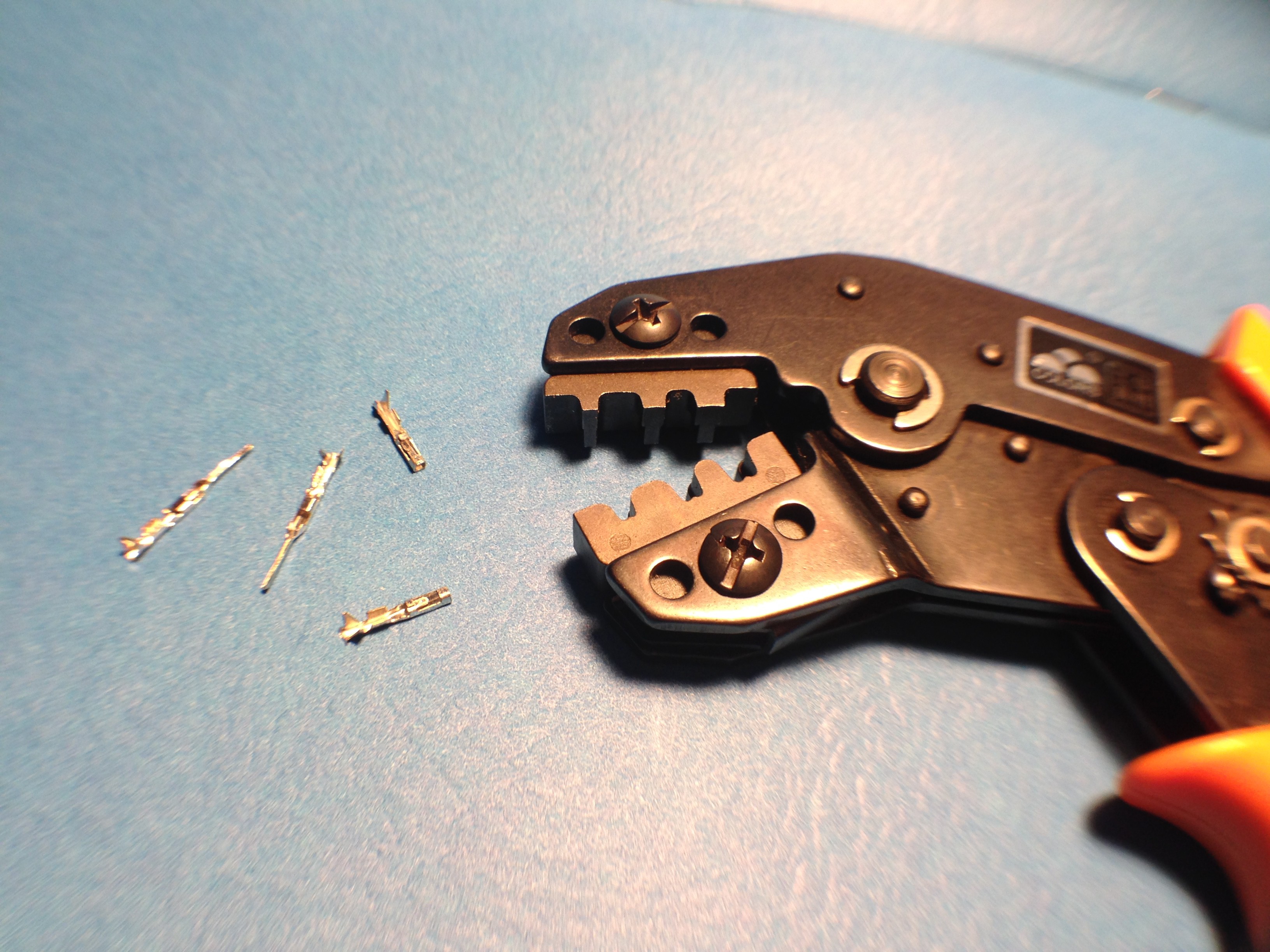
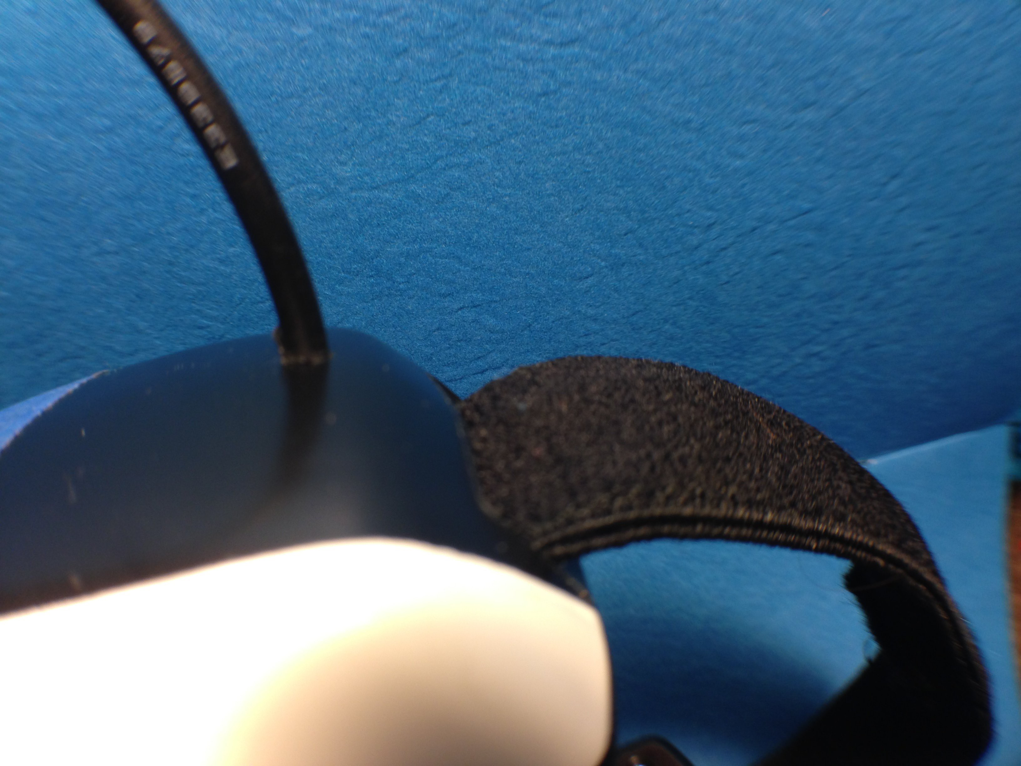
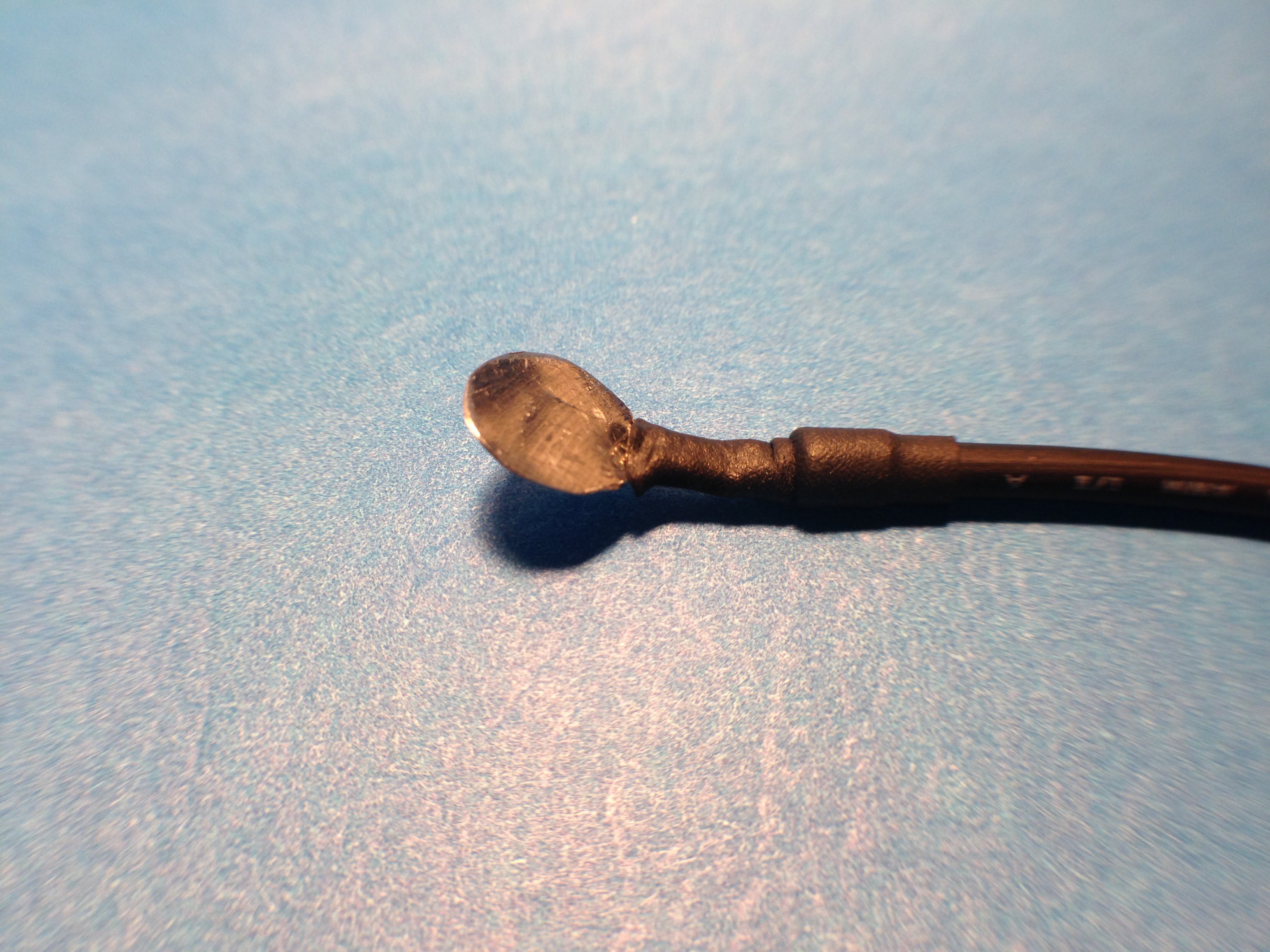
For the purposes of prototyping this project I decided to go back to using the MindFlex headset and fitting it with a different electrode and lead wire. I've finished fabricating a new electrode out of some thin stainless steel sheet metal, heat shrink tubing, 0.1” Dupont female crimp connector, and shielded 28AWG lead wire (just under 12 inches). I pulled out the original electrode, in the headstrap, and removed the lead connected to the TGAM1 board. Following that I soldered my new shielded cable to the board and then drilled a 1/8th inch hole in the MindFlex headset for the EEG lead wire to exit the headset.
![]()
![]()
![]()
My, newly fabricated, test electrode is a 10mm diameter disk (surface area of 78.5mm2 – well under the max of 150mm2). Testing of the new electrode went fine (good signal conduction). In addition, I just ordered some Ten20 electrode paste (conductive adhesive to attach electrode to scalp and provide better signal conduction).
![]()
I may attempt to fabricate some 10mm cup electrodes from some 416 stainless steel bar stock that I have (left over from another project).
I continue to inch my way along, teaching myself Java coding. Learning Java is my most challenging part of this project.
-
Designing and Coding Video Player for Neurofeedback
05/25/2016 at 06:11 • 0 commentsSwitching to using JavaFX to design video/media player. Still learning Java and how to use JavaFX Scene Builder but finally making some good progress. initially I was using Eclipse to write and debug code but finally switched to NetBeans (mainly because there is more tutorials and documentation available). Also using the code in the Brainflex project on GitHub to understand how to parse the serial data coming from the EEG signal.
Train Your Brain with NeuroFeedback
Brain hacking!!! Improve your focus and concentration by training your brain using NeuroFeedback.
 Bluetooth TX goes thru level shifter to Arduino TX (Pin 3). Bluetooth RX goes thru level shifter to Arduino RX (Pin 4).