How does it work ?
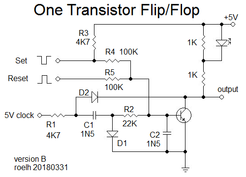
(Edit: there is an improved design in the log).
A 5 volt (TTL) clock is needed, that is in common for all flipflops in the application, and present all the time. I checked this circuit with a clock from 200kHz to 500 kHz.
The output has two states:
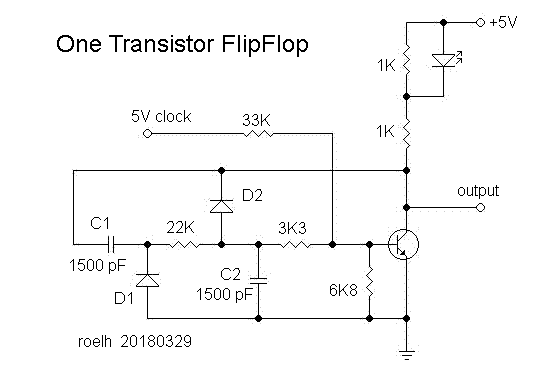
1) in the OFF state, the 5V clock signal is strongly attenuated by the 6K8 resistor and the 3K3 - C2 combination. The signal on the base of the transistor is below 0.6 Volt, so the transistor stays off (output high, LED off).
2) The flipflop can be put in the ON state by shortly applying a 5V pulse to C2 via a series resistor. This will change the operating point of the transistor. The DC voltage on C2 will provide a bias voltage to the base, and the transistor will now amplify the clock signal. So, in the ON state, the output has the clock signal, the LED will be ON. The output signal will be rectified by the C1 - D1 combination, and the resulting DC voltage will appear on C2. This closes the positive feedback loop, and the flipflop will stay in the ON state. However, the DC on C2 could be so high that the transistor is ON all the time, and that would remove the positive feedback signal. To prevent this effect, D2 is added. Each time the output of the transistor is low, it will discharge C2. When the circuit is properly dimensioned, D2 could also act as a Baker clamp to prevent saturation of the transistor.
You can bring the flipflop back to the OFF state by discharging C2, or by shortly removing the clock signal.
The flipflop can also be set and reset in a few other ways, that are not different from 'normal' flipflops or latches.
If you want the flipflop to be faster, you should make C1 and C2 smaller, and use a clock that is a few times faster than the maximum operating speed of the latch.
A drawback of the circuit is, that the output is a clock signal. To use it directly, you can adapt your application in such a way that it only uses the output at the correct phase of the clock. You could also connect a rectifying circuit to the output to have a continuous output.
The circuit was simulated by Ted Yapo (see comments in https://hackaday.io/project/7975-one-transistor-latch . (It was a slightly different design, intended for a slower clock).
This is a first design. It might very well be possible to improve it, or lower the parts count.
To my knowledge, a circuit like this has never been published before.


Anyone (most) knows that two diodes do not substitute one transistor, my quote was to be ironic, about the number of junctions. sorry, but english is not my first language, and i pretend it to be a little joke :)