zakqwy
-
Details section from 3/30/2018
04/21/2018 at 15:58 • 0 commentsI had some guests at the office this week and took a quick break at one point to play some video games on my phone. I'd recently fixed my Phonetroller (actually, I just figured out I needed to re-enable USB OTG) and was excited to use it after a 5-month hiatus. One of the guests was intrigued by the device and after giving it some thought, I realized it could be a reasonable entry for both the Open Hardware Design and Human-Machine Interface sections of the 2018 Hackaday Prize.
First, to get the open source-y bits out of the way: all design (firmware and hardware) files related to this project will be released under CC-BY-SA 4.0. Once design begins in earnest I'll get a repo up to hold official/latest fab files for everything. And I'll probably apply for OSHWA certification if the finished product gets to that point.
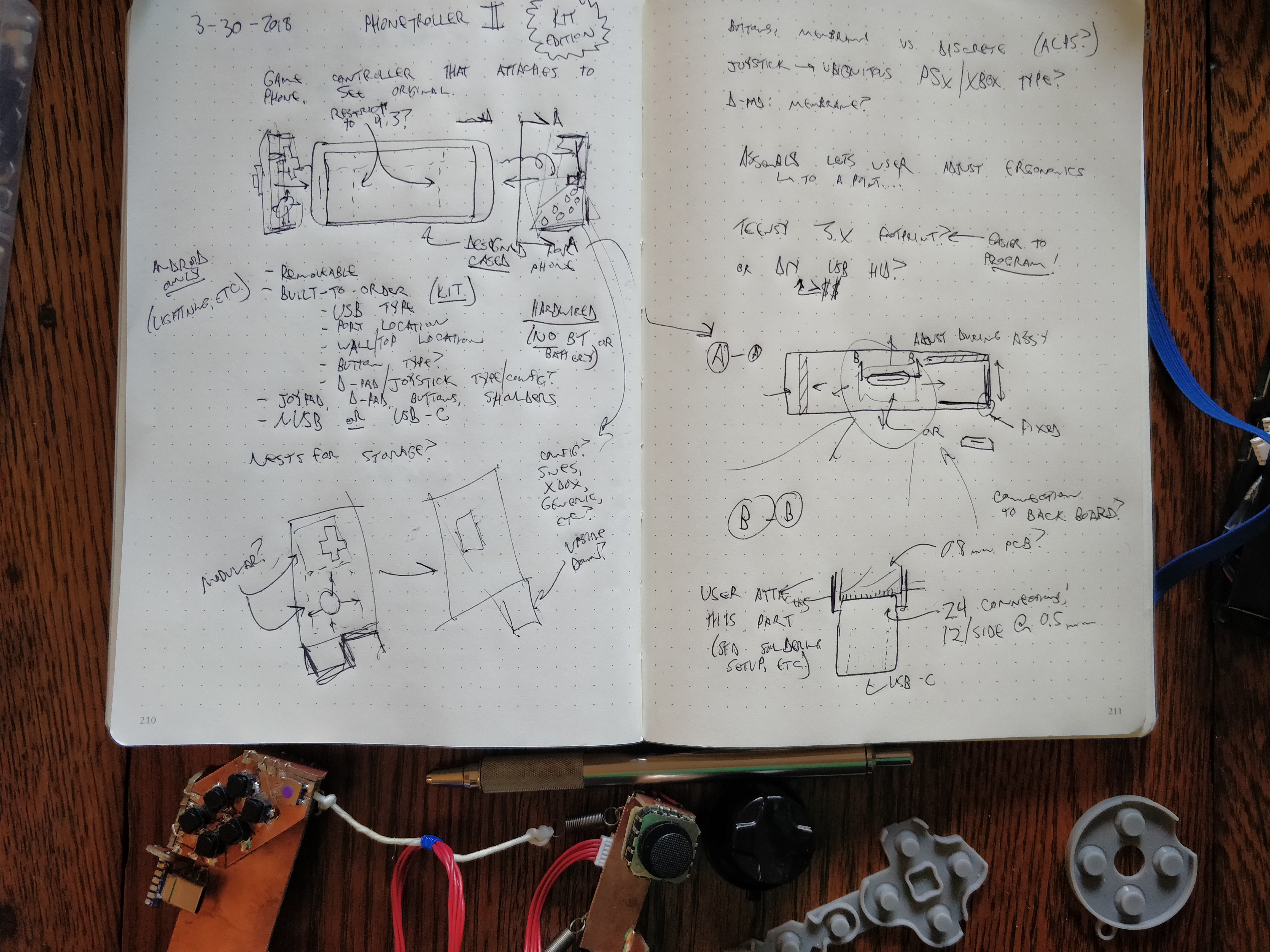
I spent a few minutes writing down some ideas in my notebook:
![]()
The most important part of this project is that it is a kit, and final assembly should be carried out by the user to customize the device for their phone. By making strategic parts of the Phonetroller II modular and user-adjustable (at least one-time adjustable), the end result can be far more compact than a commercially available device that must work for many phones. Another key aspect is the wired connection; avoiding Bluetooth means lower cost, simpler development, and no need for a built-in power source. And since most users have cases on their phones, giving them an option to customize the Phonetroller II for their device in its case will help prevent damaging the phone.
A number of other considerations need to be addressed in future iterations, including:
- how modular to make the device. Is it sufficient to make the USB connection and case thickness adjustable, or is it also worthwhile for the user to change button positions and type (i.e. D-pad vs joystick, etc)?
- what platform to use. I built the original device around the Teensy 3.2 and I'm leaning towards doing the same for this version, as it's a de facto standard among controller/keyboard builders due to its excellent USB HID support. It's also easy for the user to program via the Arduino IDE. But other chips have USB stacks too, and saving money/size is appealing.
- input device selection. I already swapped the tiny and painful buttons on the original device for some ALPS switches, but I want to experiment with other types too. In particular, at least having a rubber dome / membrane option would be nice; as compared to custom keyboards where discrete mechanical switches rule, I like the rubber dome feel better for thumb buttons.
- input device selection, other side. joystick? D-pad? both? If these bits aren't modular I'll need to decide which to use, and what type. I use both when gaming as some are better suited for some games and vice-versa. Whatever the case, I'm ditching the tiny generic PSP-style joystick in the original as its precision and force requirements and linearity and everything else are subpar at best.
- aspect ratio. the prototype covered a little bit of screen real estate on either side, but this makes no difference for 4:3 games and (again) saves space. but 16:9 games are also a thing and blocking screen area for those could look bad.
I likely won't have a ton of time to spend on this project as work stuff is quite busy right now. But I'll submit these plans (probably with a lot more detail added) to the Hardware Design Challenge, and if I have time I'll build a prototype (or several prototypes) and enter the Human - Computer Interface Challenge as well.
-
Second prototype finished and [extensively] tested. Many lessons learned.
04/18/2018 at 18:23 • 1 commentI wrapped up the second Phonetroller prototype this past weekend, just as a massive April snowstorm hit Minneapolis:
![]() above, 14" of snow by Saturday evening with another 5" or so to come. Yes, we almost got half a meter of snow. In mid-fucking-April.
above, 14" of snow by Saturday evening with another 5" or so to come. Yes, we almost got half a meter of snow. In mid-fucking-April.
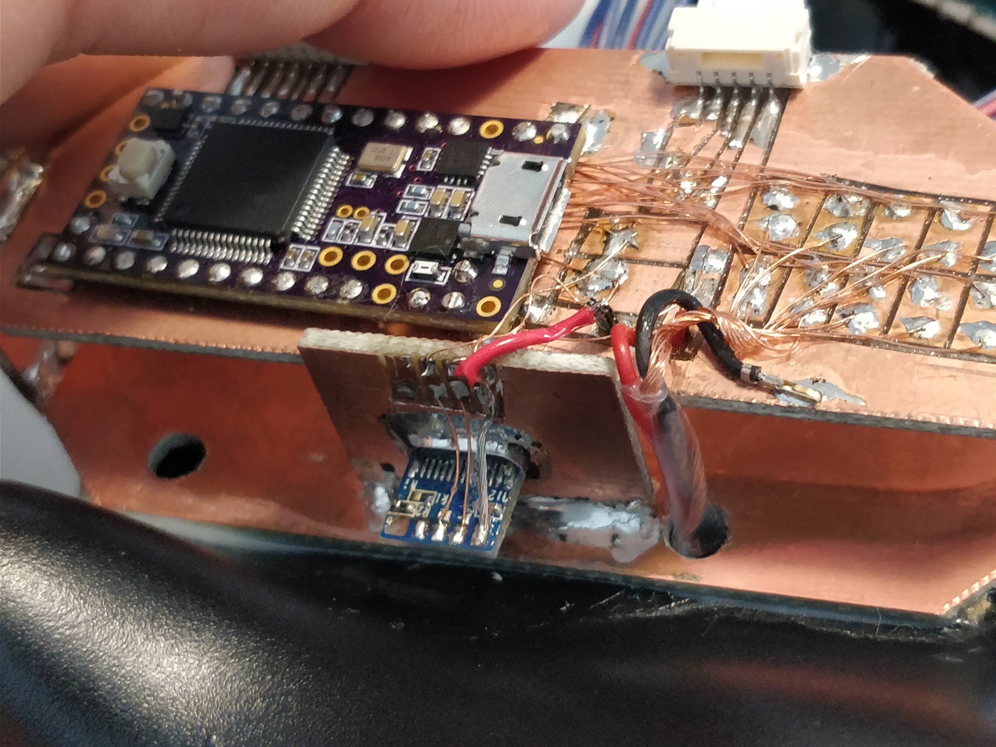
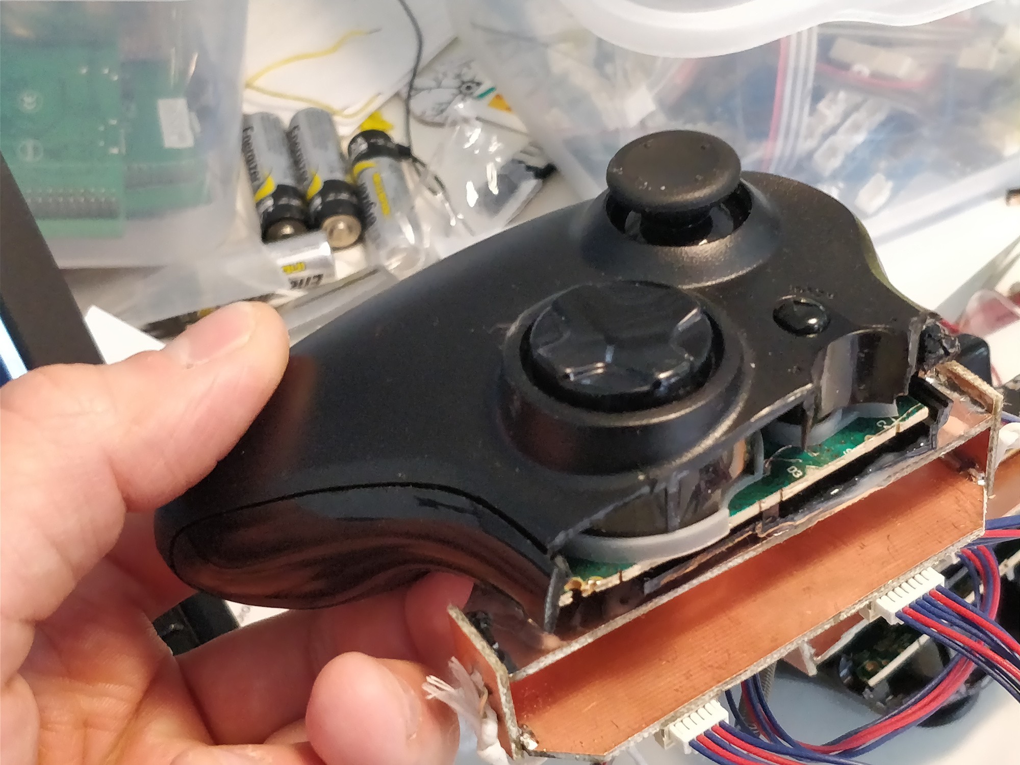
Getting wires tacked onto the right parts of the controller boards proved to be a bit more tedious than I'd hoped. The XBOX 360 PCB seems to use 6mil (0.15mm) traces and the vias are generally tented with the same conductive rubber crap that covers the membrane button contacts; even after scraping it off I had trouble soldering to the vias. I ended up sticking the end of the 34 AWG enamelled copper wire into the vias, scraping soldermask off traces for the soldered connection, then securing the connections with a bit of conformal coating:![]()
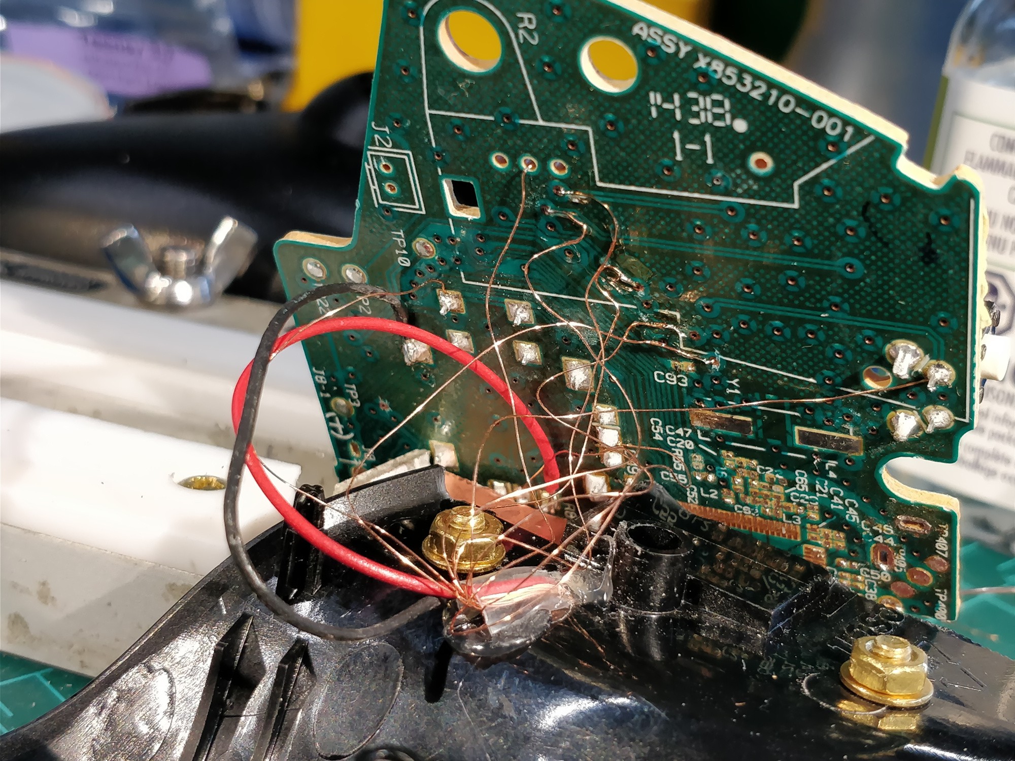
![]() These images show the righthand side of the controller; I didn't allow quite enough extra enamelled wire for the board to lay flat during assembly which made the whole process that much more difficult. Note the heatshrunk cable passthrough above as well; I hot-glued it flat to keep it out of the way of the PCB.
These images show the righthand side of the controller; I didn't allow quite enough extra enamelled wire for the board to lay flat during assembly which made the whole process that much more difficult. Note the heatshrunk cable passthrough above as well; I hot-glued it flat to keep it out of the way of the PCB.
Then this shit happened:![]()
Turns out soldering brass studs onto FR4 isn't a great technique. I suspect this one moved a bit during solidification; the fracture surface shows evidence of significant porosity:![]()
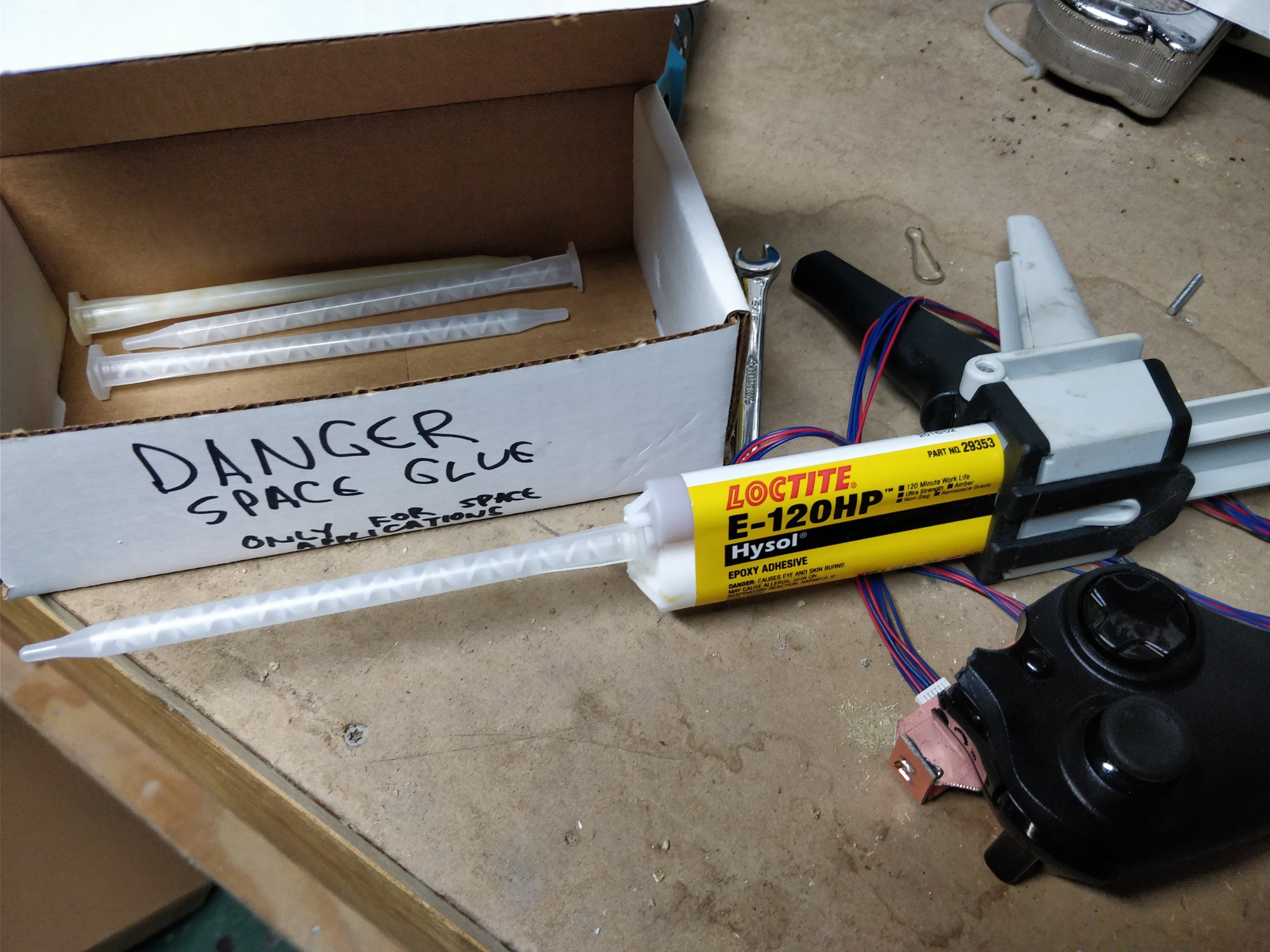
Sounds like a job for . . .![]() SPAAAACE GLUE! Not the prettiest solution but this (along with the remaining studs) has held up well:
SPAAAACE GLUE! Not the prettiest solution but this (along with the remaining studs) has held up well:![]() above, a bit of space glue squeezed out between the FR4 and the ABS controller shell. Also note the continued heatshrink tube for the button signal wires.
above, a bit of space glue squeezed out between the FR4 and the ABS controller shell. Also note the continued heatshrink tube for the button signal wires.
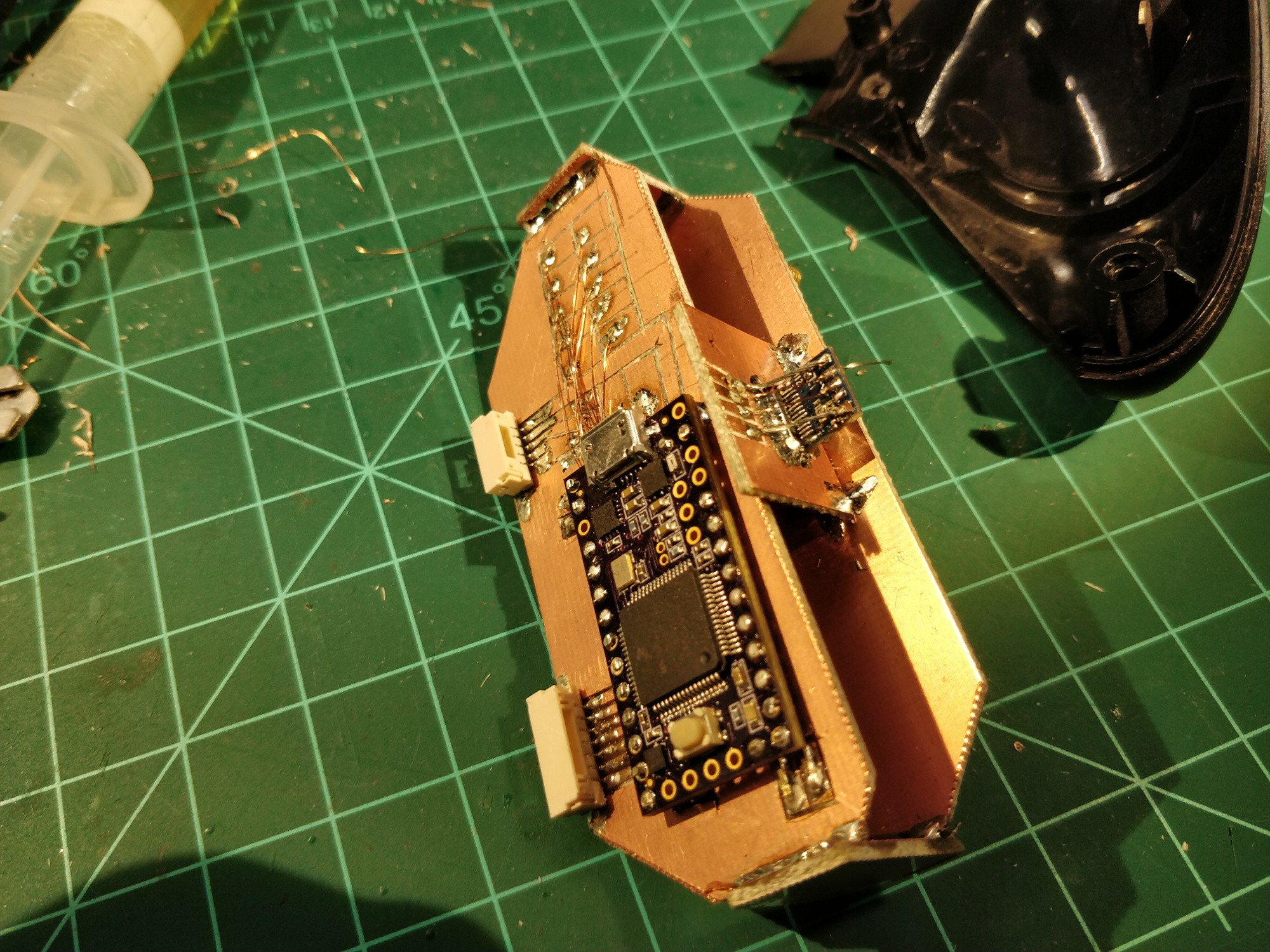
The lefthand control was pretty simple to build. I added a few cm to the enamelled wires which made assembly substantially easier, and the PCB isn't nearly as complex as the righthand one (which has the processor and connector):![]()
![]()
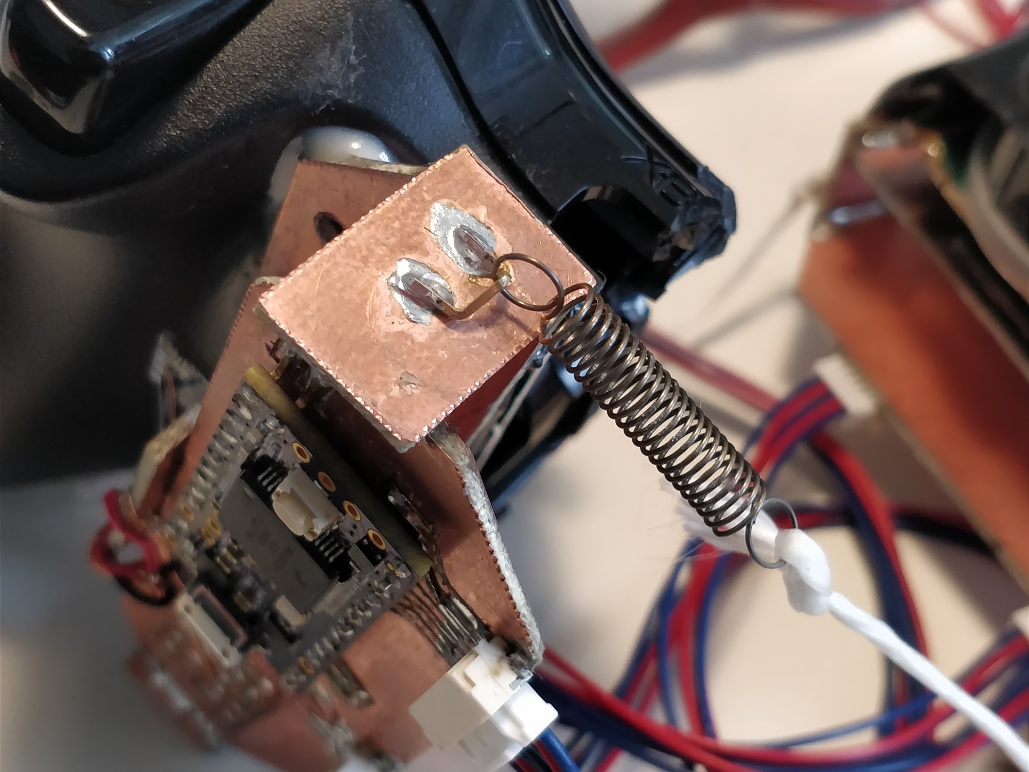
The last steps were to add mounting points for springs and strings, and build up the two JST cable assemblies:![]()
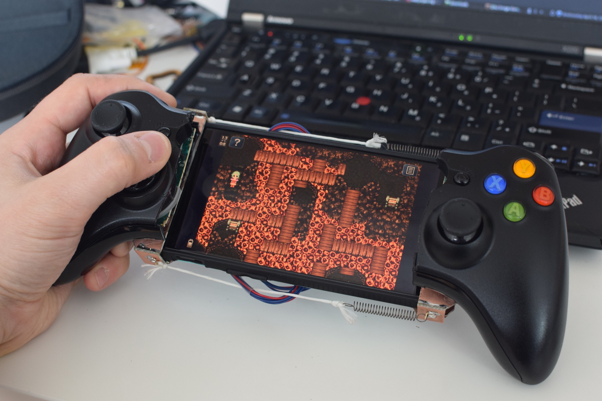
After finishing the construction and updating the Teensy code (nothing terribly special there beyond a bit of debouncing), I bought the Android port of Square Enix's Final Fantasy VI and settled in for an excellent weekend:
![]()
![]()
above: ah yes, this is excellent.
Overall the experience was terrific. I put around 10 hours on the controller between Saturday and Sunday and learned a ton. A few notes that should guide the next iteration:
- Android apps have varied and generally shitty support for controllers, and it's not always spelled out in the Play store. I also bought FFIX but couldn't get the input device to change from touch to controller; Sonic 2 (yes, there is an Android port!) had some button mapping issues; and other games, like PUBG Mobile, don't support controllers at all. Even FFVI isn't perfect; the D-pad and selection buttons work well (which covers 95% of play), but I still had to touch the screen occasionally. Kinda annoying for a game that was originally built around controller-only play (as it's from the SNES).
- The headphone jack is frustratingly inaccessible. I was using my Koss Porta Pros whose 45-degree 1/8" phono plug could fit around the controller back, but I had to carefully plug in the headphones while I was sliding the phone into the dock. Not convenient.
- More recently I did experience a few reliability issues; sometimes even with OTG Storage engaged the phone doesn't seem to recognize the input device. I think this is a phone issue as the hardware seems fine. Also pulling the phone out of the controller immediately crashes FFVI.
- The design, while it looks pretty awesome (in a sorta cyberpunky way), is sharp and bulky and somewhat delicate. The ergo bits from the XBOX360 controller halves take up a ton more space in my bag compared to the first prototype.
- The phone itself is set back pretty far from the joysticks and buttons. As I mentioned above, FFVI and many other games with controller support still require _some_ touchscreen interaction, and having the screen a bit closer to the user would make this easier. Having said that, I'm still able to tap where I need to without dropping the controller. Still easier than the devices that mount the phone _above_ the joysticks.
I can't control the biggest issue; lack of Shovel Knight, Ori and the Blind Forest, and Risk of Rain. Those three recent platformers are some of my favorites and would have been a delightful way to test the device. So if you have any recommendations for Android platformers with solid external controller support -- please let me know!
-
Slight course adjustments and some difficult-to-decipher notes
04/13/2018 at 02:36 • 0 commentsI have a few pages of written/drawn notes I'd like to document and discuss here. Before doing that, some higher level project direction thoughts. These paragraphs are a bit disparate, but I promise I'll tie 'em together at the end.
First, this project was never conceived around solving a world problem. Millions are hungry, fresh water is scarce, wealth inequality is rampant, climate change is accelerating, and cities are polluted. A ton of other Hackaday Prize 2018 (and previous) entries are doing a fantastic job coming up with novel ideas to address society's biggest needs; just spend a few weeks on the new projects list and you'll see a few bubble up. No, the Phonetroller was always about getting a solid gaming experience onto a mobile platform -- that's about it. But it would be nice to, at the very least, not make things worse.
Second, it's really hard to get game controller ergonomics right. I putzed around with a few button types and handle configurations and never had anything close to the experience with a mass-market controller. They all have their quirks, whether it's the square corners of the NES controller or the encoder joystick (and generally insane layout) on the N64, but nearly all performed their primary task well: they became an extension of the user, to the point that directing on-screen character movements became instinctive and control fidelity stopped limiting player ability. None of the (few) designs I've built come close to that standard.
Third, customization really can deliver an improvement in user experience, and not just due to the inherent satisfaction gained by building something oneself. Anyone who has used a generic phone docking station knows the frustration and potential for damage caused by poor fit; in the case of a handheld controller, fit is that much more critical as the controls must withstand the stresses of constant handling and movement. My experience with my Phonetroller prototype(s) has shown me what a really solid phone-accessory interface can feel like. It's great, and that only happens if you build the accessory to fit your phone (in its case!).
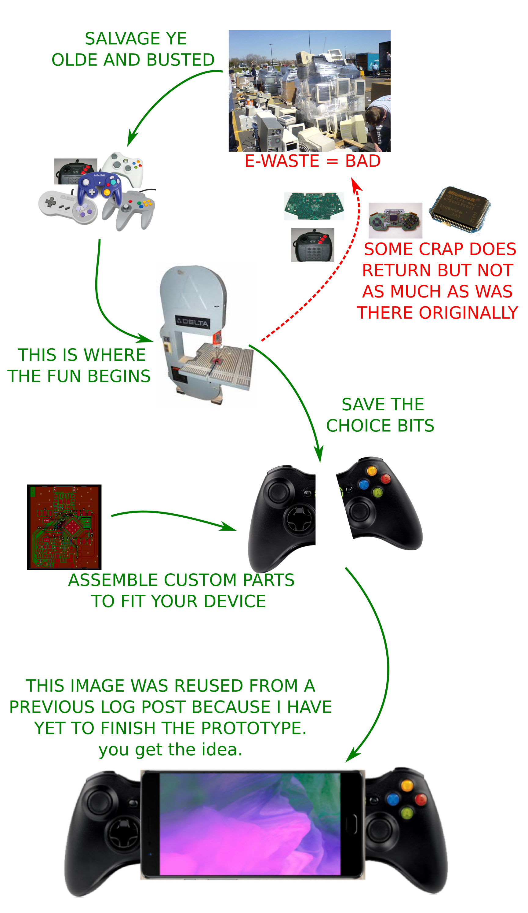
This all comes together in a shitty flow chart:
![]()
In a nutshell: reduce e-waste by upcycling parts of discarded gadgets (controllers, in this case) into modern devices. Going after mass-market platforms (XBOX360 controllers to start, but maybe DualShocks, etc someday?) means it will hopefully be worthwhile to develop custom parts and instructions for retrofitting a specific device.
I extended the concept pretty far in my mind, particularly after I decided that wholesale replacement of the controller PCB is the way to go (more on that in another post). A few ideas:
- 3D print a companion fixture for each controller chassis so it can be held securely and precisely, then release toolpaths for milling the features required to adapt to a phone (although it's important that this can be done manually as well).
- Modularize the phone connection parts to the point that the controller can be re-adapted to a new phone once the current one is no longer used (hopefully recycled!).
I doubt that game controllers constitute anything approaching a detectable percentage of all e-waste (let alone all trash); this project is less about reducing numbers as it is about encouraging people to think about reusing stuff instead of throwing it away. And the way the project does that is by, as highlighted earlier, providing a superior experience compared to existing products on the market.
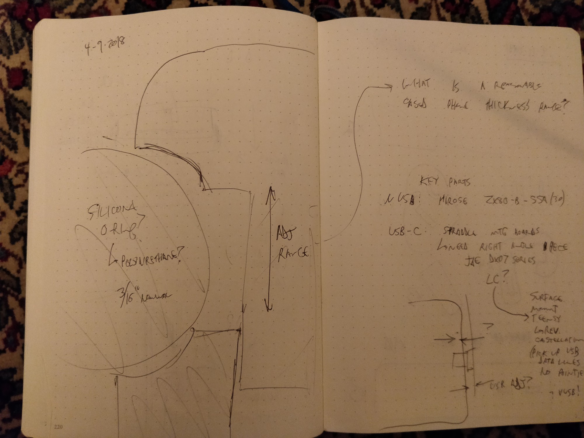
Anyhoo, I'll try to distill all the blabbing above into the Project Details section at some point, hopefully before the first Prize deadline on 4/23. In the meantime, here are the aforementioned notes I jotted down earlier this week along with annotations. You'll note that .. ahem .. parts of the project were going in a different direction then. Changes can happen at any time so it's best to write it all down! Boom!
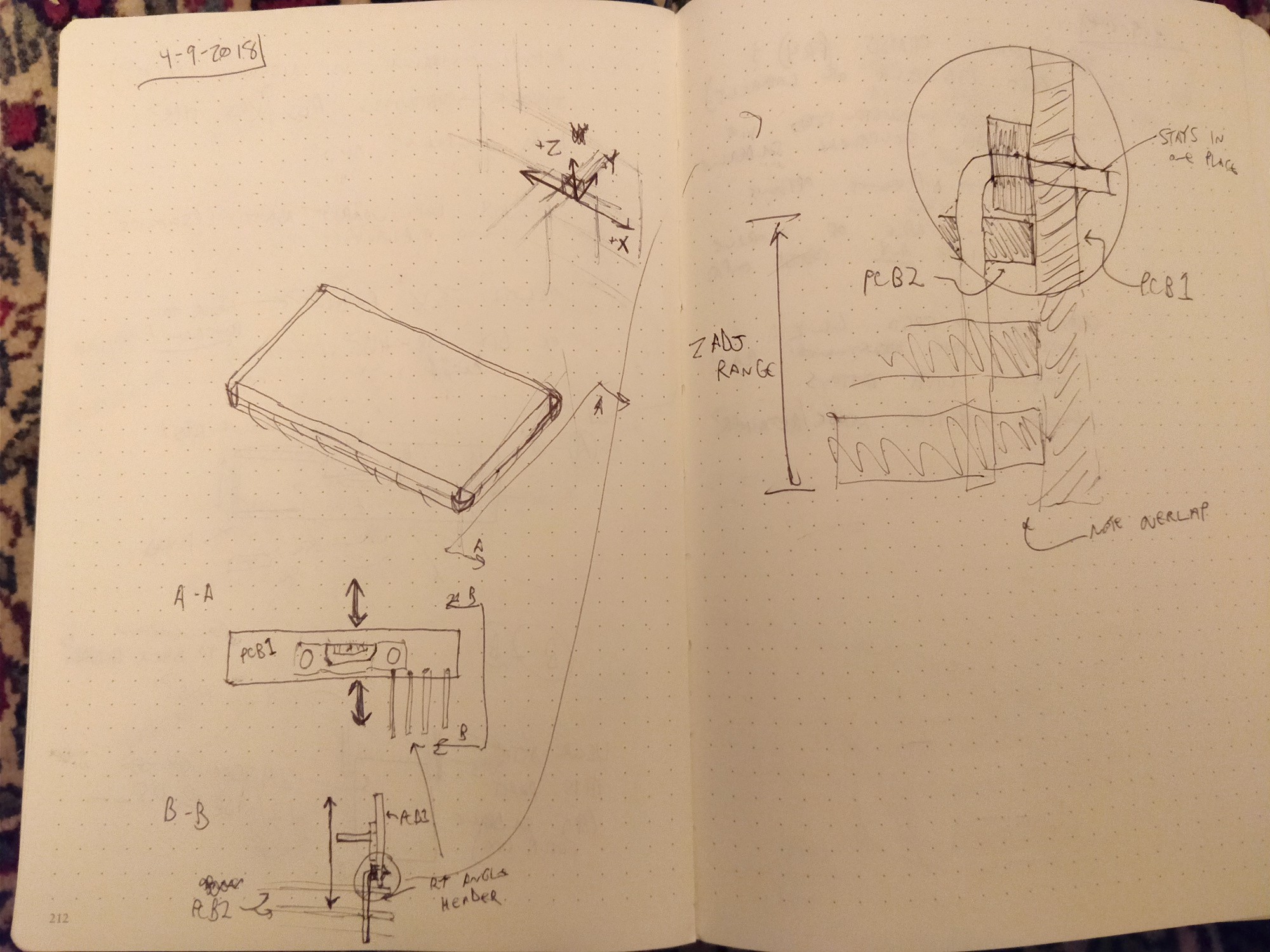
![]()
Above, I started thinking about how to allow users to adjust the uUSB or USB-C port location to fit their device. My hope is to produce a standard set of PCBs that are adaptable to a reasonable range of Android phones. However, the current assembly method I use -- plugging stuff into my phone and then fillet-soldering sheets of FR4 together -- isn't very device-friendly and is pretty easy to mess up. On the right page detail of section B-B, I show using a right-angle header to allow limited adjustment range while keeping the physical part of the soldering assembly simple. In this example, PCB1 has the short legs of the header soldered prior to assembly, and PCB2 can be adjusted vertically to ensure a snug fit. I think it still makes sense to have some long solder fillets to strengthen everything up, but using headers to do the initial tacking seems solid. Plus they can be used for electrical signals.
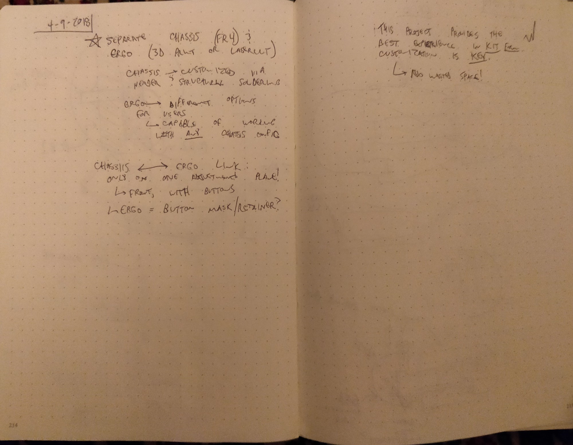
![]()
Above, the starred bit at the top is the key part -- separate the physical chassis, which supports the phone and electronics and is made of FR4, from the bits that the user contacts. Seems obvious looking at any consumer electronics product out there but it's a move away from Phonetroller (I). Then I started down a rabbit hole of a 3D printed 'ergonomics package' -- this was before I seriously considered repurposing existing controllers.
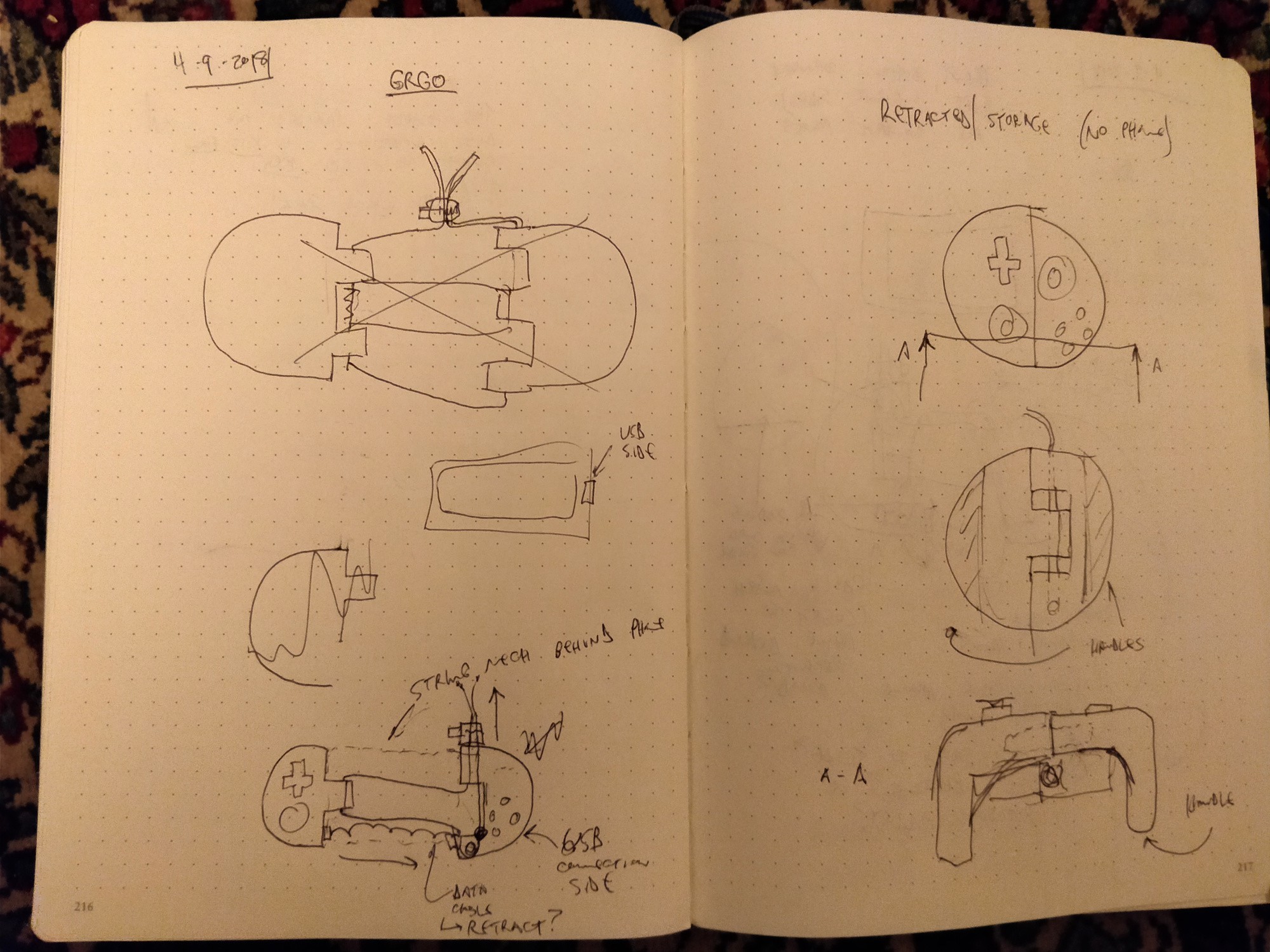
![]()
Above, thinking about a removable controller in terms of its store-ability. This concept mates together into a round puck secured using a drawstring; the same drawstring can be loosened and adjusted to secure the device on the phone. I imagined this as beefy paracord and one of those springy push-button cord retainers often found on coats and such. The bottom right image shows the design with downward-turned handles. Producing good ergonomics seems like it would require a lot of iterations with the 3D printer (understatement of the century, and apologies to all the industrial designers out there...)
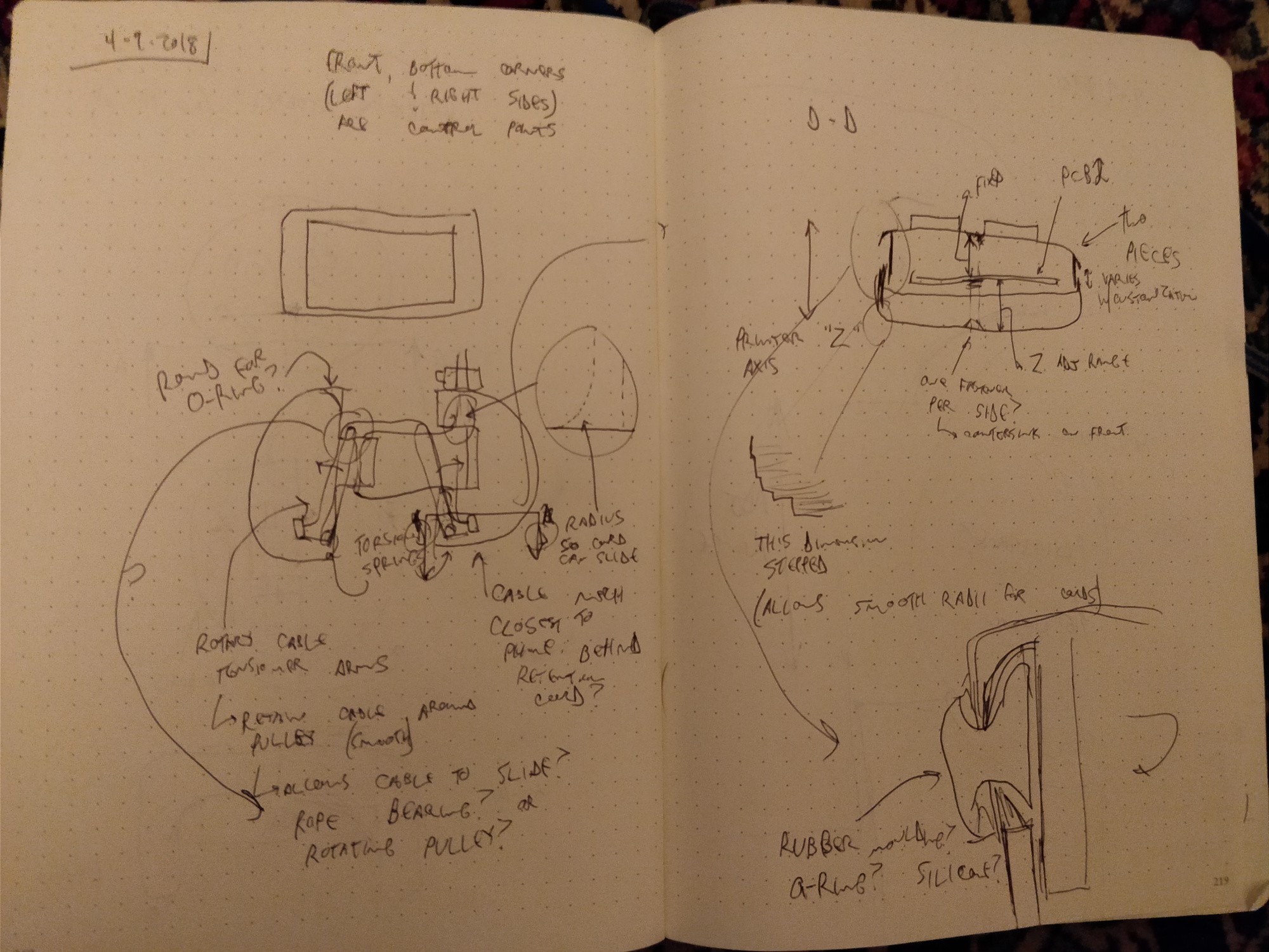
![]()
A bit further down said rabbit hole. On the left, thinking about cable tensioning mechanisms; I'm still keen to avoid putting anything wireless (and power-hungry and fussy and expensive) into the design, so the two sides need to be linked somehow. The overly complicated concept there shows a pair of spring-loaded retractable arms with pulleys on the top that extend to keep the cord out of the way and .. yeah, springs are probably fine for now. On the right, thinking about how to design the 3D printed model -- maybe a clamshell approach with a gap to accommodate different device thicknesses...
![]()
... and a giant O-ring to fill the ensuing panel gap, because why not? Silicone? Polyurethane? In any case, the righthand page covers a few potentially important parts -- a micro USB dock connector, and a reasonably suitable USB-C plug (not a dock connector, as those don't seem to exist).
We're supposed to get a fuckload of snow this weekend so I'll hopefully get the prototype wrapped up. Excitement!
-
I cut my XBOX360 Wireless controller in half
04/12/2018 at 04:16 • 0 comments... and it felt great. Made a good bit of progress on the next Phonetroller prototype this evening, starting with some destructive fun:
![]()
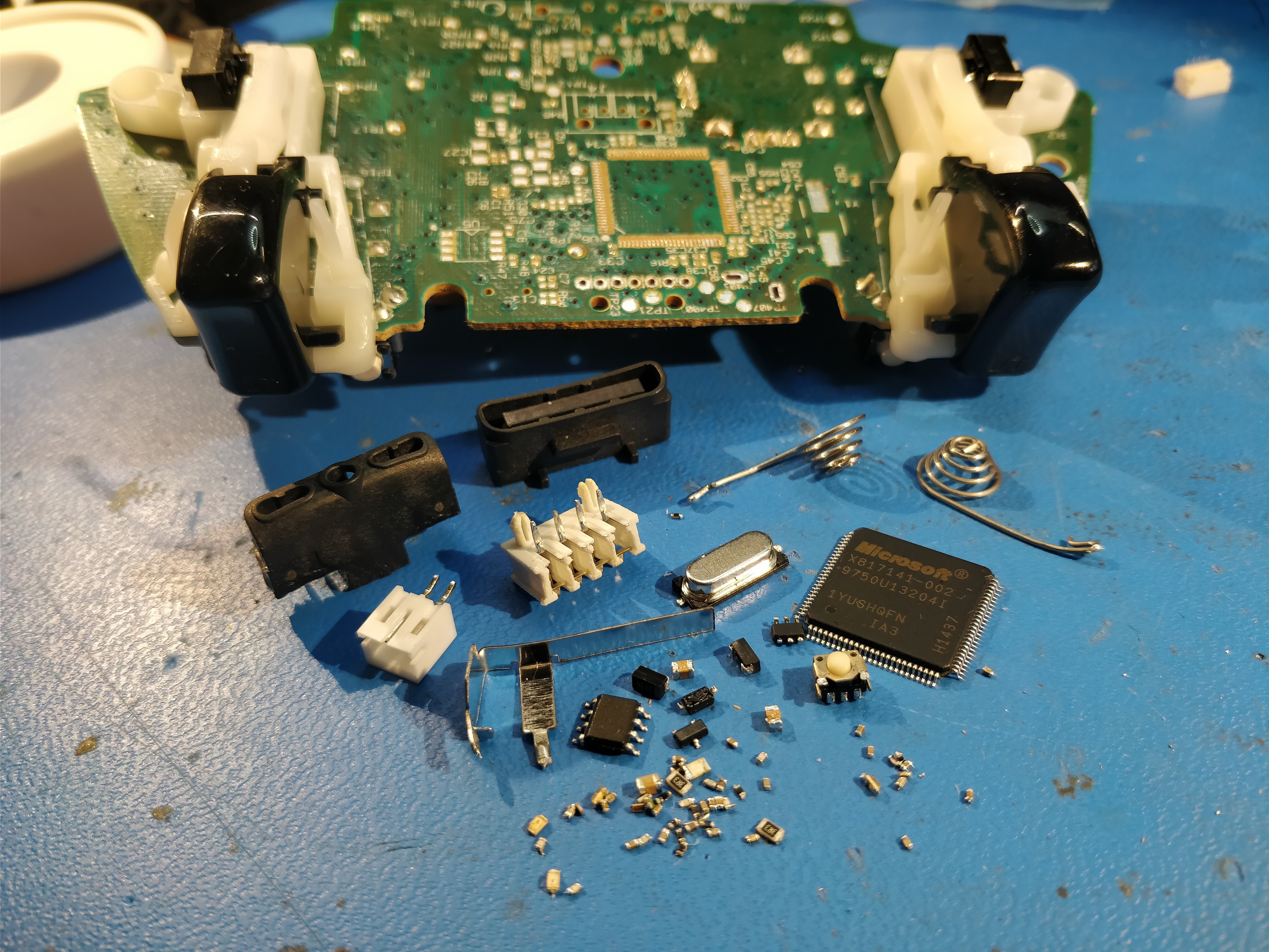
Above, all of the non-control-related (i.e. potentiometers and shoulder switches) parts removed, including that pesky Microsoft-branded wireless SoC. Lots of passives scattered around the board that I probably could have kept, but once the hot air gun starts going it's hard to resist...
![]()
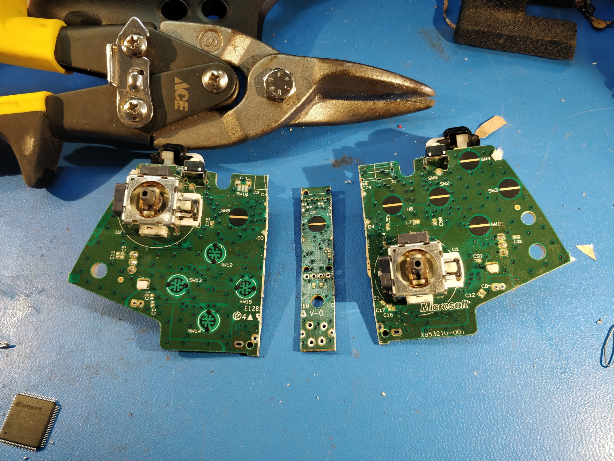
Above, I snipped the board in half and managed to extract a ~12mm strip of unused material from the middle. The PCB is some kind of phenolic that tends to shatter a bit, so I scored it first and had to clean the cut up with some sandpaper afterwards.
![]()
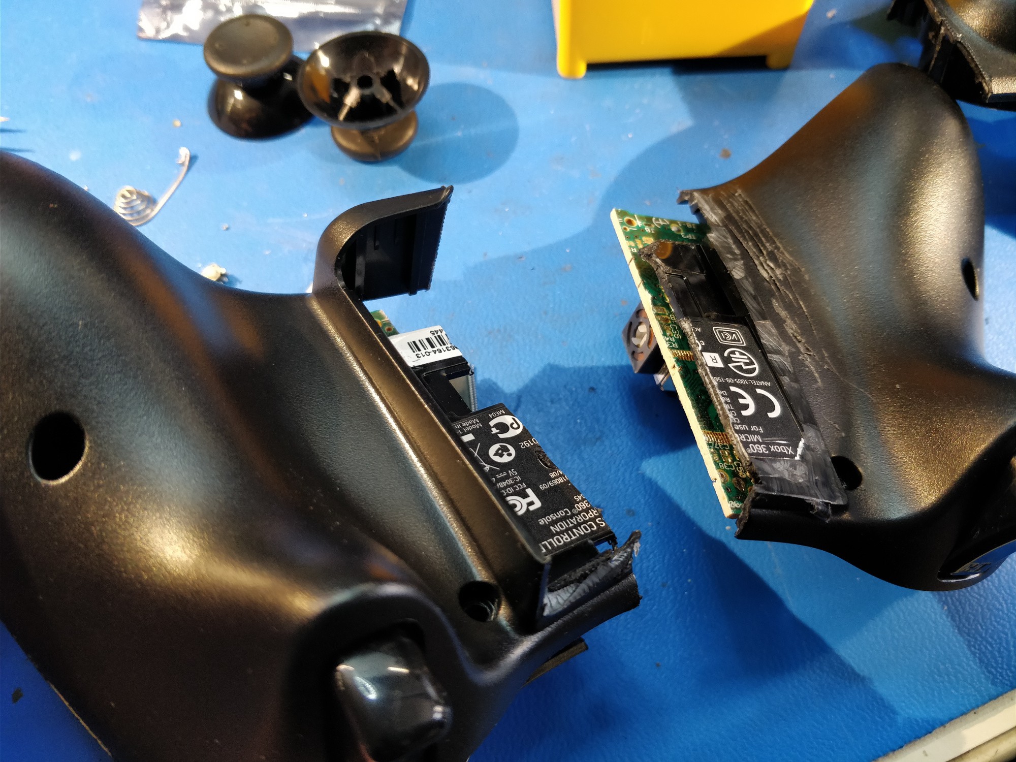
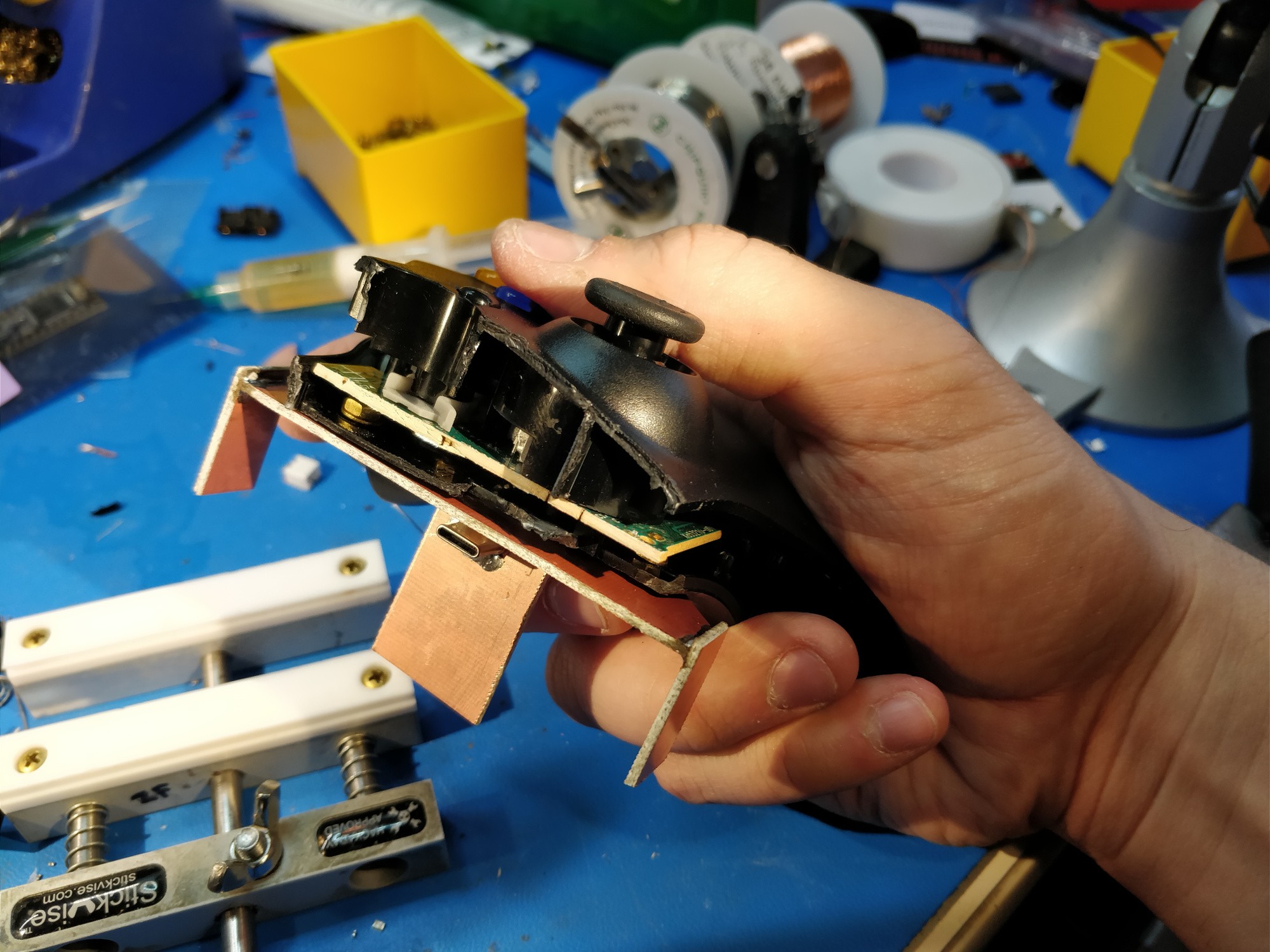
Above, test-fitting the boards after slicing the controller's ABS shell in half. I started fiddling around with phone position around this point, and ended up trimming the plastic battery case remnants off the back (as seen on the right).
![]()
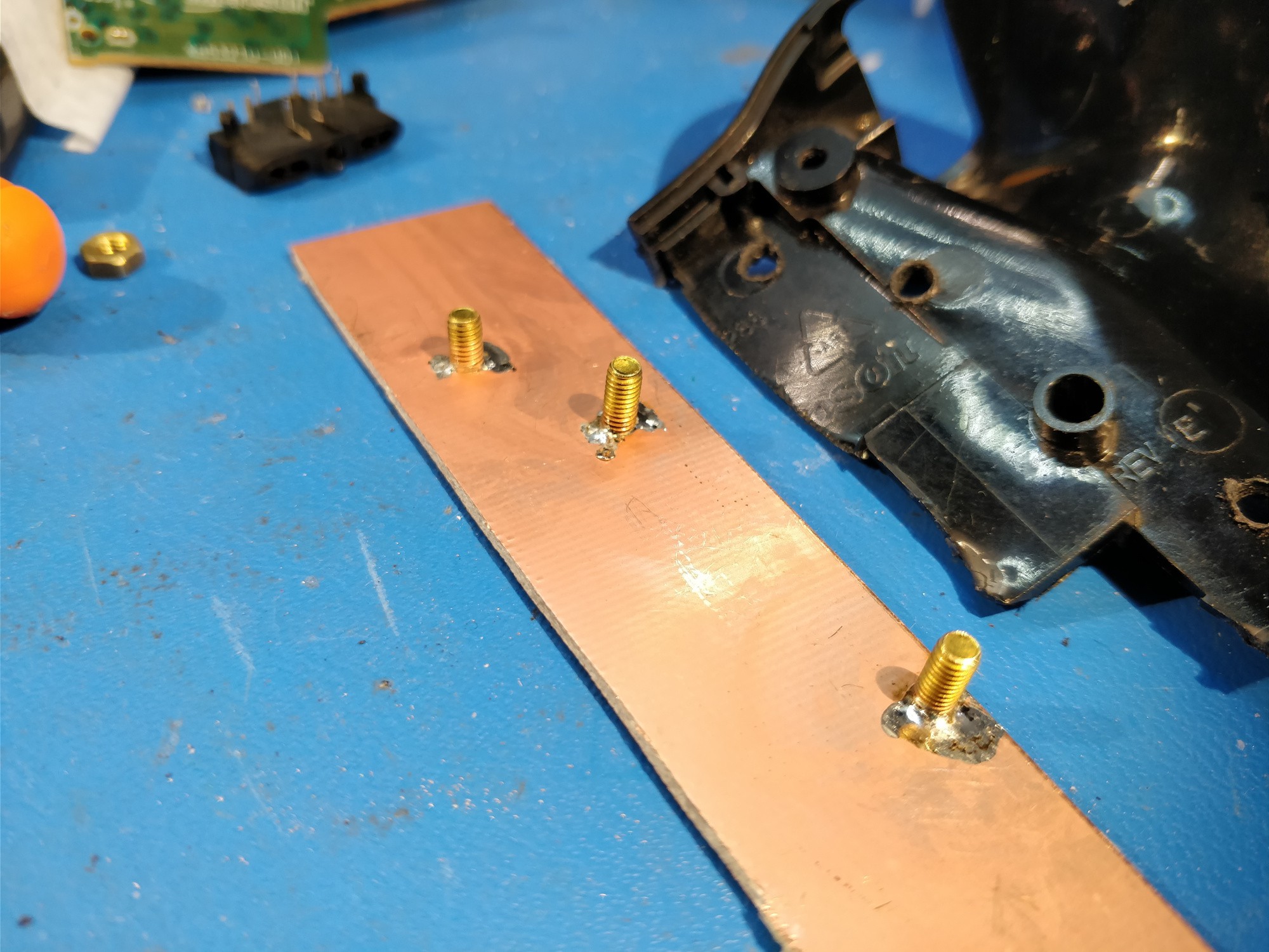
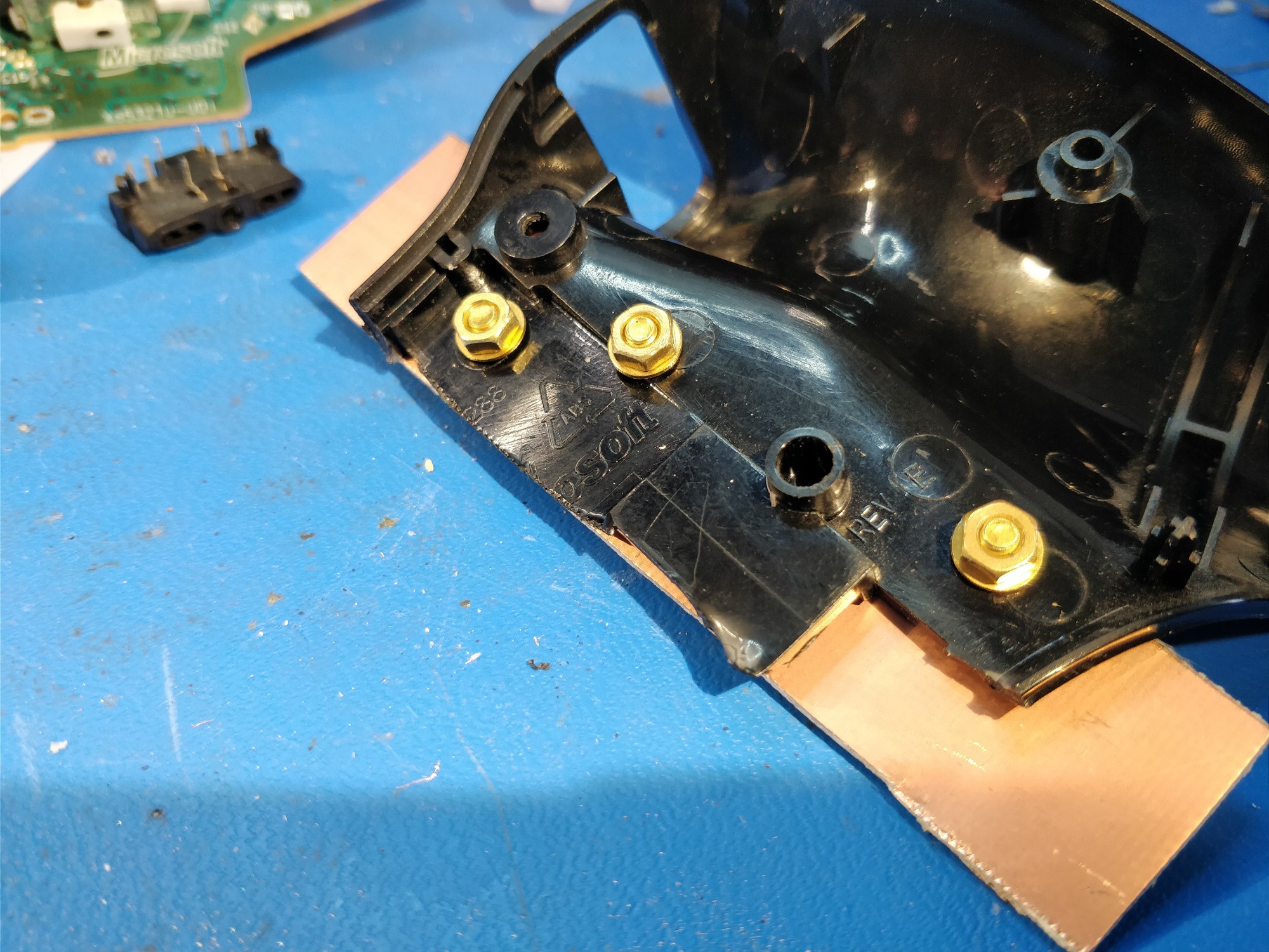
Above, I soldered a few cut down brass M3 machine screws to a piece of FR4. It would probably be easier to just glue the boards to the ABS shells, but this way everything is removable and much easier to work on.
![]()
Above, drilling mounting holes with a crappy file. Might be time to bring a drill in to the lab.
![]()
Above, success! And surprisingly strong.
![]()
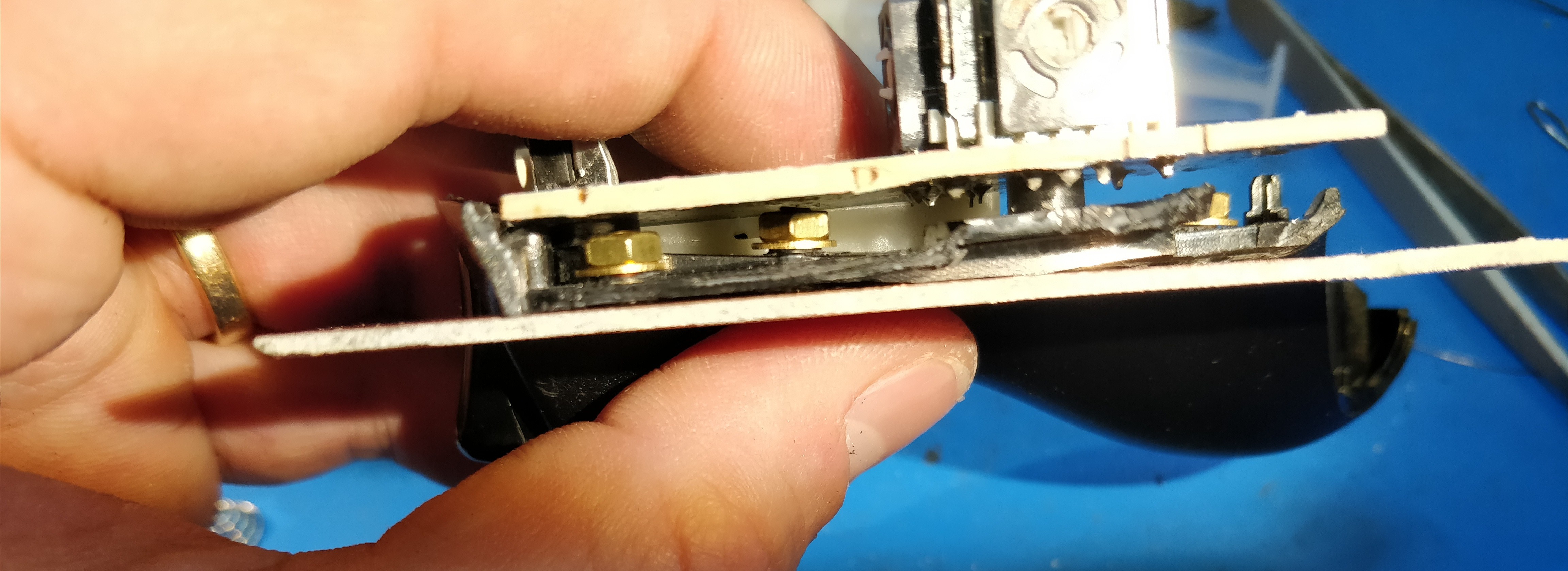
Plenty of clearance!
![]()
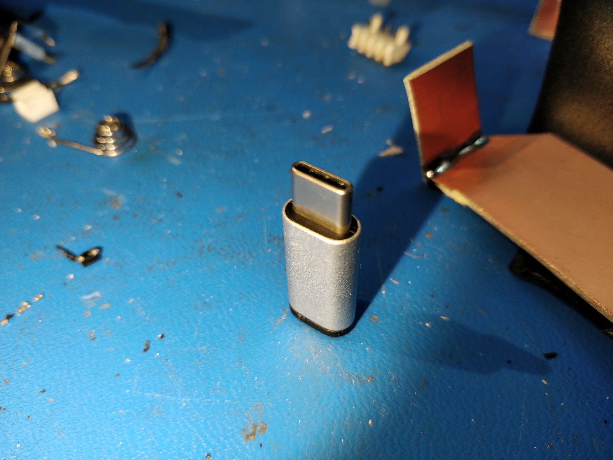
I had a uUSB to USB-C adapter lying around from the original Phonetroller prototype (when I bought a few at a local store). Time for more destruction!
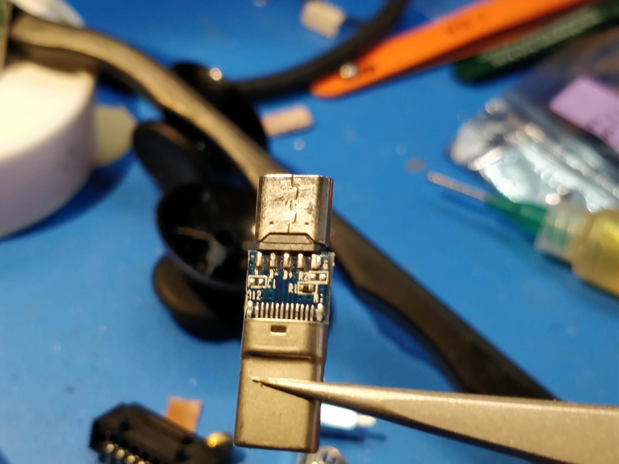
![]() Above, another nicely labelled PCB. R1 and R2 are for CC-1 pulldown and pullup, so this board can actually be used for a host or device. I ended up having to swap the resistor for a 5k one, otherwise 5V didn't appear on the VBUS line. Yeah I don't really want to read the USB-C spec, but this seemed to work.
Above, another nicely labelled PCB. R1 and R2 are for CC-1 pulldown and pullup, so this board can actually be used for a host or device. I ended up having to swap the resistor for a 5k one, otherwise 5V didn't appear on the VBUS line. Yeah I don't really want to read the USB-C spec, but this seemed to work.![]()
Above, more bodgy file drilling. I tacked the USB connector shell in place after adjusting the insertion depth using my phone (in its case).
![]()
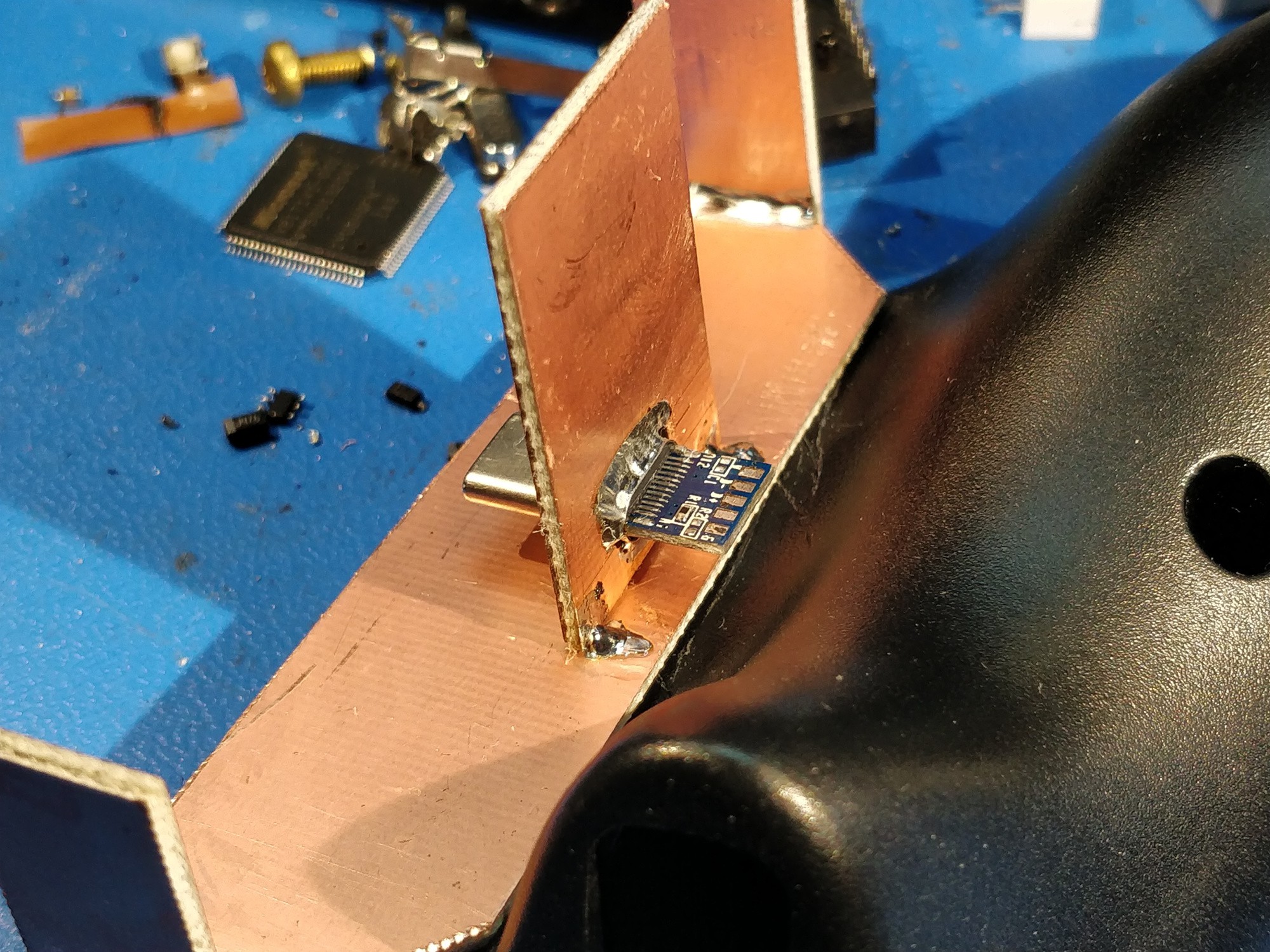
Above, some severe USB-C connector abuse. The shells solder nicely and transform into quite robust dock connectors.
![]()
Above, test fitting the works together.
![]()
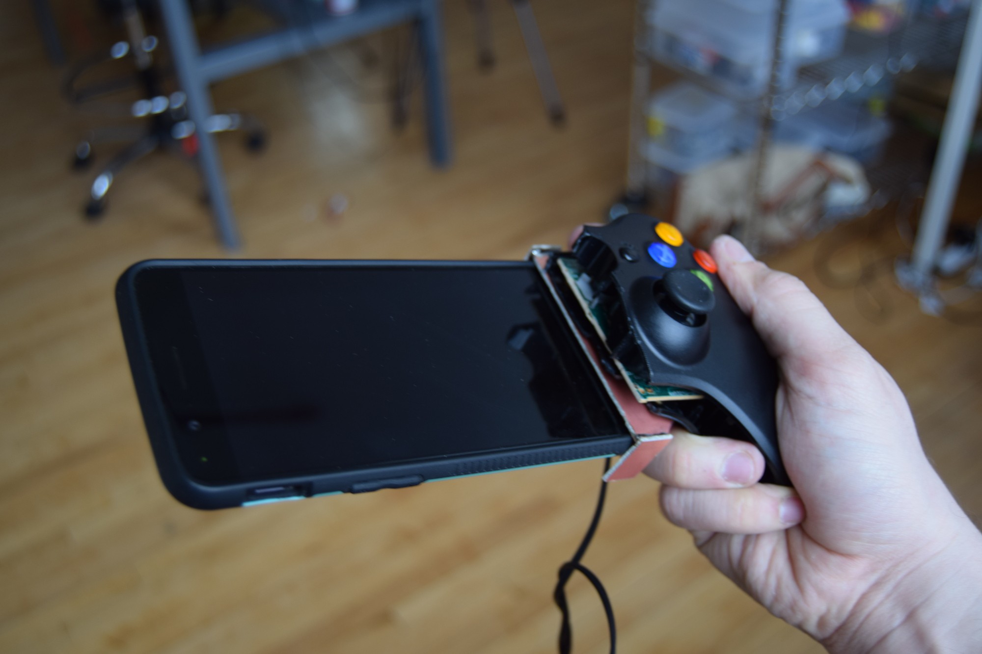
Above, a blurry picture (mostly because DSLRs don't like to be used one-handed from the left side) of the phone test-fit on the controller for the first time. The back plate isn't in place so this is a bit wobbly, but the friction from the side panels and the connector itself were more than sufficient to keep it from falling out.
![]()
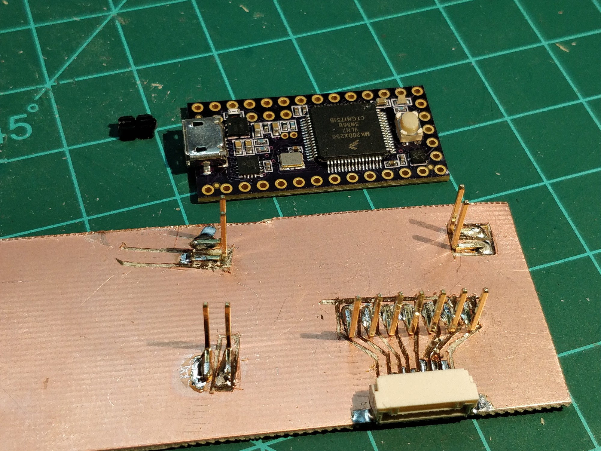
Above, starting to carve up the control board that will fit under the phone. This board will be on the righthand side (as with the original), so it needs signal wires to pick up the lefthand controls. 12 conductors needed total: power, ground, 3 potentiometer wipers, and seven buttons. The 7-pin JST GH takes care of the latter; I took the time to 'route' this bit to save on wire jumble.
![]()
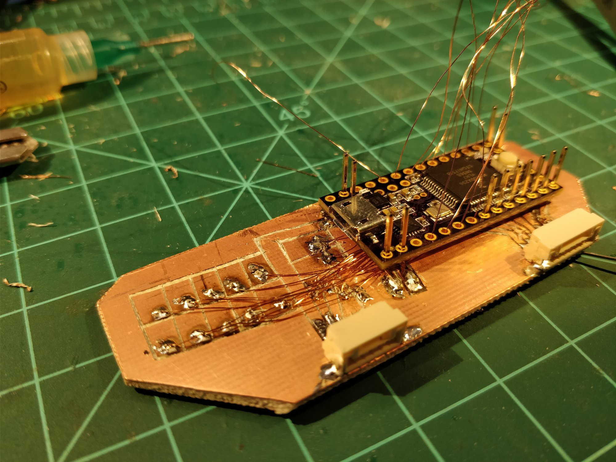
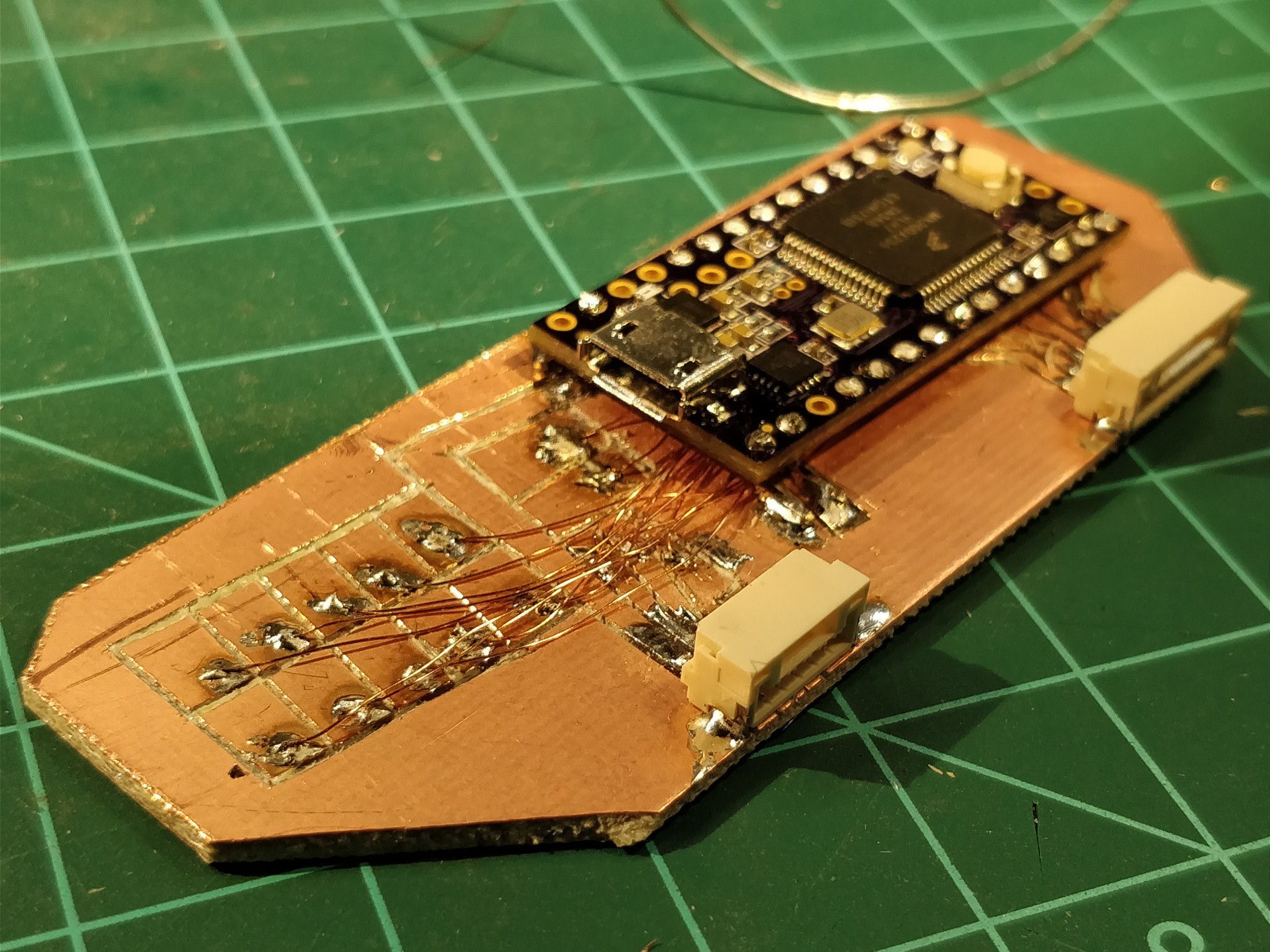
Above, the 5-pin JST connector has been added along with a bunch of 34AWG magnet wire. Note the ten pads at the top -- these are breakouts for the right side controls (also 7 buttons + 3 pots), so I can land them in an intermediary spot after securing the Teensy.
![]()
Above, this part gets a bit chaotic. The key is to allow a good bit of extra wire so everything can be threaded before soldering. Also note that I broke out the USB D+ and D- pins to their own pads (directly in front of the uUSB connector) -- quite important, as they are only accessible via rear SMD pads!
![]()
Soldered and trimmed. The wires tuck nicely under the processor board; a bit of conformal coating will keep them protected and secured once everything is tested.
![]()
Above, the rear board is mounted to the rest of the assembly after another round of test-fitting with the phone (which was used to take this and most of the other pictures).
![]()
Above, a back-to-back comparison with the original Phonetroller righthand board.
So. A lot of progress tonight. Still to do:
- modify the lefthand shell to accept a PCB mount
- construct the lefthand phone cradle
- carve the lefthand PCB
- break out the various connections on the (now two) XBOX PCBs
- f-f-f-f-f-firmware! (which should be a fairly simple port from the Phonetroller I).
I also spent a bit of time last week sketching out some larger picture concepts in my notebook. I think I have a few ideas for a more refined and kit-able version -- something that doesn't require quite so much customization to fit a given phone. More to come.
-
Plans for the next prototype
04/02/2018 at 00:06 • 0 commentsI originally intended to dive right in to Phonetroller II PCB design. I have a few important issues to figure out there; namely, how to make the USB power port swappable (uUSB vs Type C) and adjustable, along with how to generally configure the rest of the chassis. However, after using the existing controller prototype for an hour or so with fresh ALPS switches I feel this build strategy may be premature. The new switches are light-years more comfortable than the tiny thumb-denters I originally installed, but they're a bit too linear for my taste. And a quick survey of the vast array of PCB-mount switches I've purchased or salvaged over the years suggests all tactile switches have some issues; the travel is too short, the force requirement is too high, the actuator is too low, etc. Time to re-examine the prevailing gamepad industry button: the rubber dome.
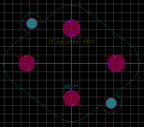
Above, some time ago I played around with KiCad footprints for a set of replacement rubber dome elements I found on eBay. These particular parts were designed as generic drop-in replacements for SNES gamepads; enough sellers were around (and enough knockoff SNES controllers are still produced) that I thought this could be a good starting point (or, alternatively, I could use a handful of solderable rubber-dome switches and make my own arrangement). The footprint itself hasn't been tested and I'd like to round off the edges of the spiral traces, but if made with ENIG finish it should get the job done.
My main concern with rubber dome switches involves the ancillary requirements: namely, one needs to provide an actuation surface and the mechanical support that keeps that actuator in line with the button, retained, etc. Even the clearance between the button and the sidewall scares me; I don't want switches that bind. I think the answer here is to see what other folks in the community have 3D printed and laser cut and start with that.
The other issue with the current prototype, which I haven't addressed at all yet, is the joystick. I can't get used to the PSP-style 'nub' joystick; maybe my thumbs are clumsy, but it's just too small for any sort of precision work. And I'm starting to feel the need for two joysticks. I don't play a ton of dual-analog games, but such a setup does allow for far more sophisticated play. Hmm.
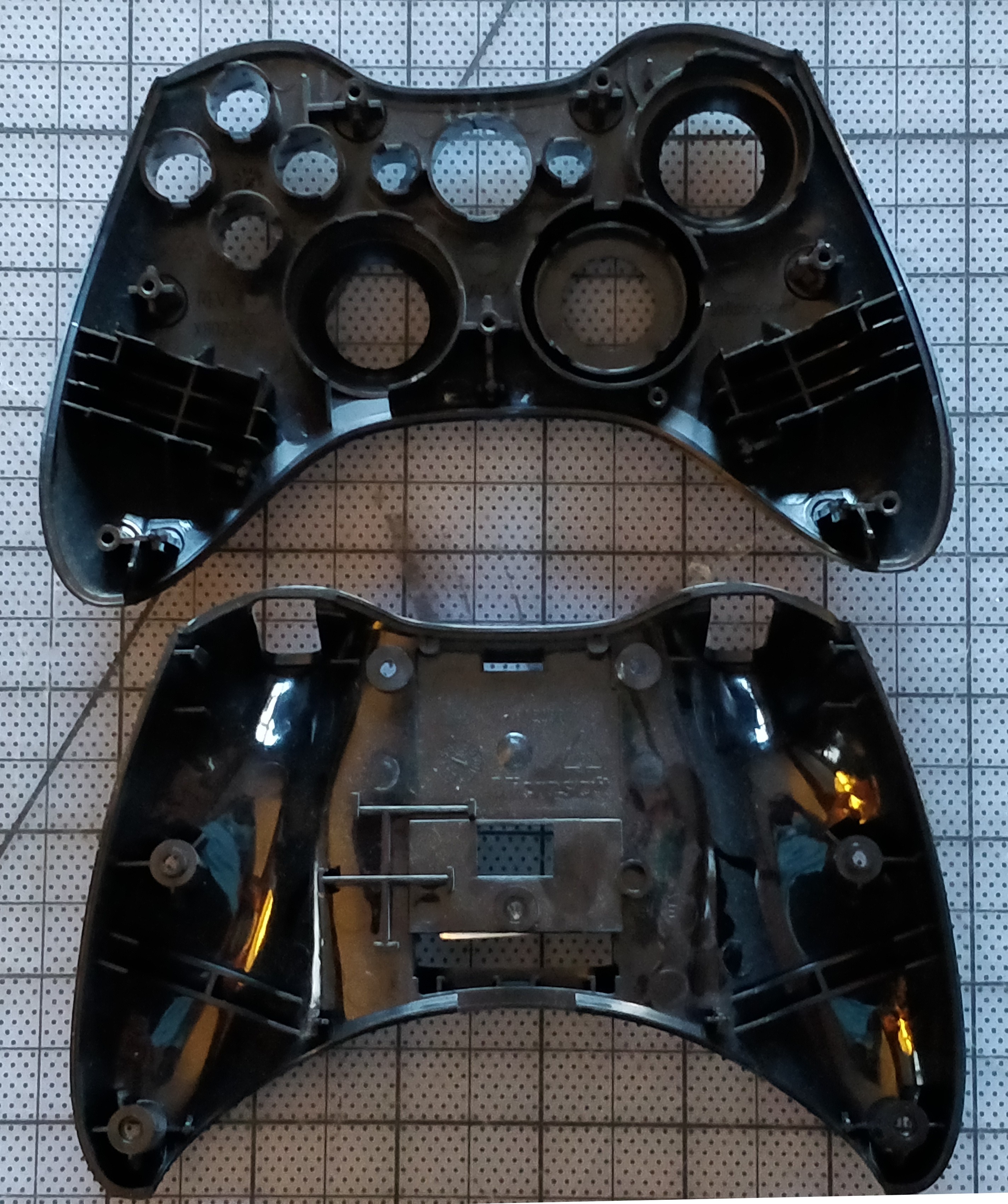
I need a prototype _now_, so it's time for some more destructive franken-prototyping. Years ago I purchased a number of XBOX 360 wireless controllers for my PC. Soon after I took one apart and dumped the parts in a box; today I exhumed this unlucky controller and gave it a closer look:![]()
The last prototyping run focused on remove-ability, compactness, and FR4 construction madness. This one will focus on adapting what I feel is an excellent interface platform to my phone in a similar manner to the previous design. I need to get over the hump of poor usability and actually enjoy playing games on my phone with the damn thing. Normally I'd just fire up the soldering iron ( / glue gun / band saw) and go, but in this case I think a bit of advanced planning will make the result much better.
Uhh, yeah, you get the idea. Something like the 'render' above, but I'll probably be a bit more clever with the layering so the phone's top and bottom bar are under the joysticks and the controls are a closer together. I'll likely shoot for a 16:9 aspect ratio and will try to make the whole thing removable, but no guarantees there -- it may be easier to just build it into a cheap off-the-shelf case for the phone and use a wire to plug in the USB-C port.
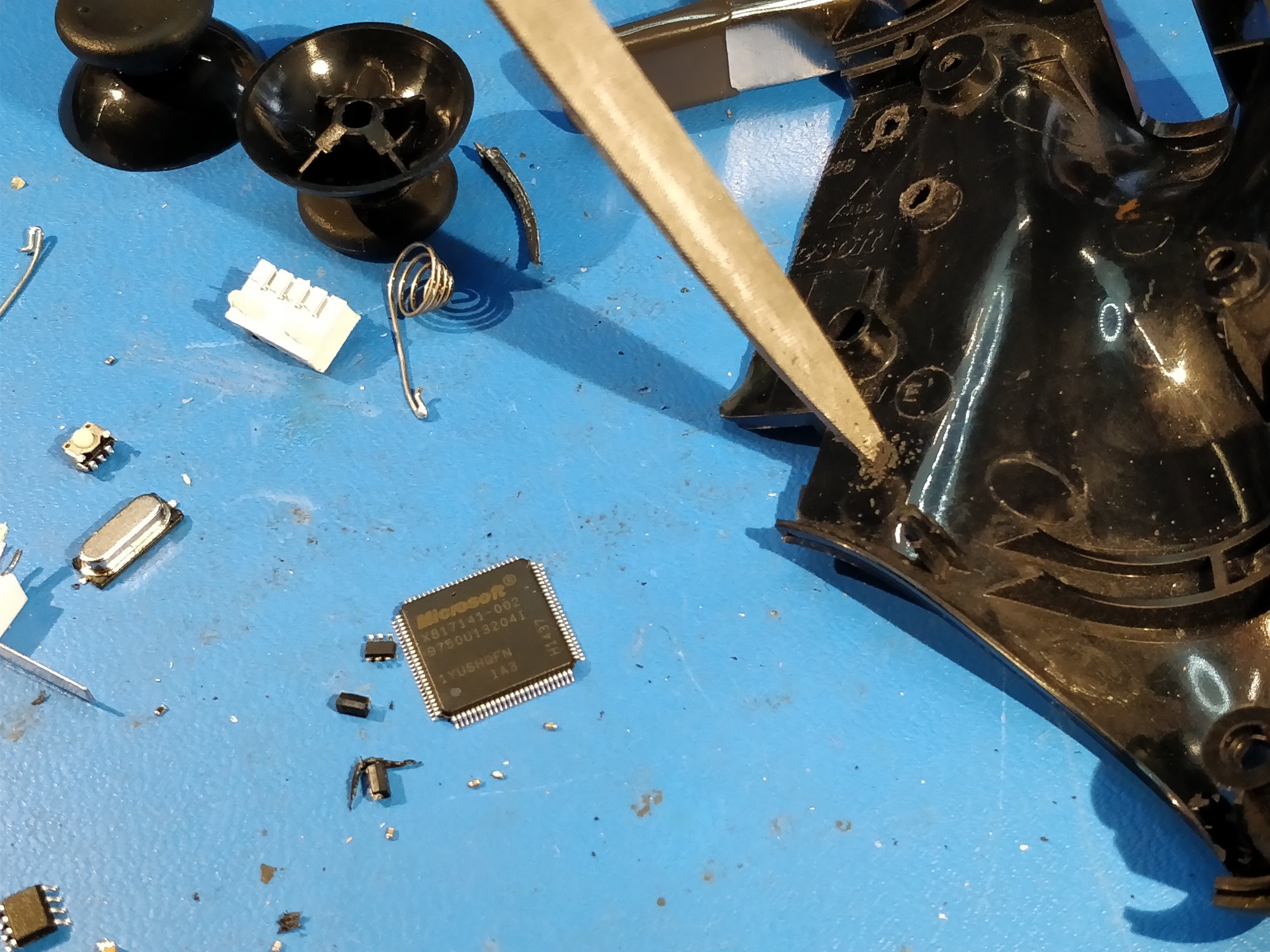
The plan is to carefully hot-air off all the components, cut the main board in half, wire up the switch contacts and potentiometers (6! crazy!), cut the case in half, and kludge everything together so it's durable enough to survive in my bag for a month. After a closer look at the controller's design, I think this is a reasonable path despite being fairly destructive.![]() The PCB isn't FR4; it seems like some cheaper composite. With any luck it will survive the hot air treatment. The wireless SoC looks pretty proprietary; even the SOIC-8 to the left of the main processor is laser-etched 'XBOX'. My guess is that the latter chip is an EEPROM and the former is a slightly customized off-the-shelf microcontroller with an onboard radio, but I'm not interested in playing around with either as even in the event of success that would make this a mostly firmware exercise (far from my strong suit). And besides, I need to cut a section out of the PCB to keep the joysticks as close to the screen as possible. And even without a datasheet I can tell that the microcontroller wouldn't survive a trip through the band saw.
The PCB isn't FR4; it seems like some cheaper composite. With any luck it will survive the hot air treatment. The wireless SoC looks pretty proprietary; even the SOIC-8 to the left of the main processor is laser-etched 'XBOX'. My guess is that the latter chip is an EEPROM and the former is a slightly customized off-the-shelf microcontroller with an onboard radio, but I'm not interested in playing around with either as even in the event of success that would make this a mostly firmware exercise (far from my strong suit). And besides, I need to cut a section out of the PCB to keep the joysticks as close to the screen as possible. And even without a datasheet I can tell that the microcontroller wouldn't survive a trip through the band saw.
![]() The rear of the controller PCB shows the membrane button traces and a few mounting details. I don't need anything between the D-pad (marked 'SW12 - 15' above) and the right joystick, so I'd like to cut that PCB region out entirely. The hole in the middle (above the 'V-0' silkscreen) is one of half a dozen mounting points for the PCB and probably plays a big role in preventing PCB flex when the controls are used; my planned cut eliminates this hole, so I'll need to shore the board up elsewhere.
The rear of the controller PCB shows the membrane button traces and a few mounting details. I don't need anything between the D-pad (marked 'SW12 - 15' above) and the right joystick, so I'd like to cut that PCB region out entirely. The hole in the middle (above the 'V-0' silkscreen) is one of half a dozen mounting points for the PCB and probably plays a big role in preventing PCB flex when the controls are used; my planned cut eliminates this hole, so I'll need to shore the board up elsewhere. ![]()
Electronics should be fun. Ripping parts off the boards means I can probably pick up the momentary and resistive contacts wherever is convenient, and the traces are all generous enough that re-using the board won't be nearly as difficult as I've encountered in the past. Stay tuned...
 above, 14" of snow by Saturday evening with another 5" or so to come. Yes, we almost got half a meter of snow. In mid-fucking-April.
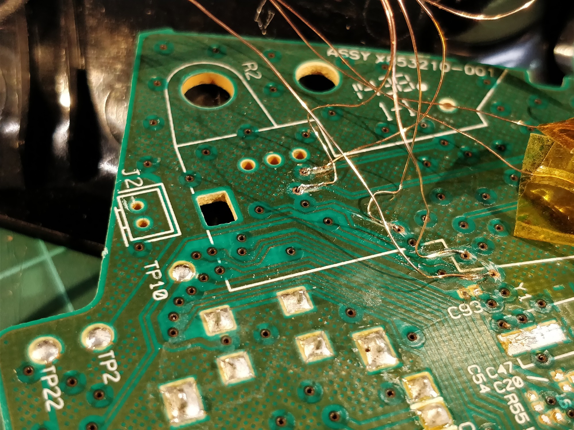
 These images show the righthand side of the controller; I didn't allow quite enough extra enamelled wire for the board to lay flat during assembly which made the whole process that much more difficult. Note the heatshrunk cable passthrough above as well; I hot-glued it flat to keep it out of the way of the PCB.
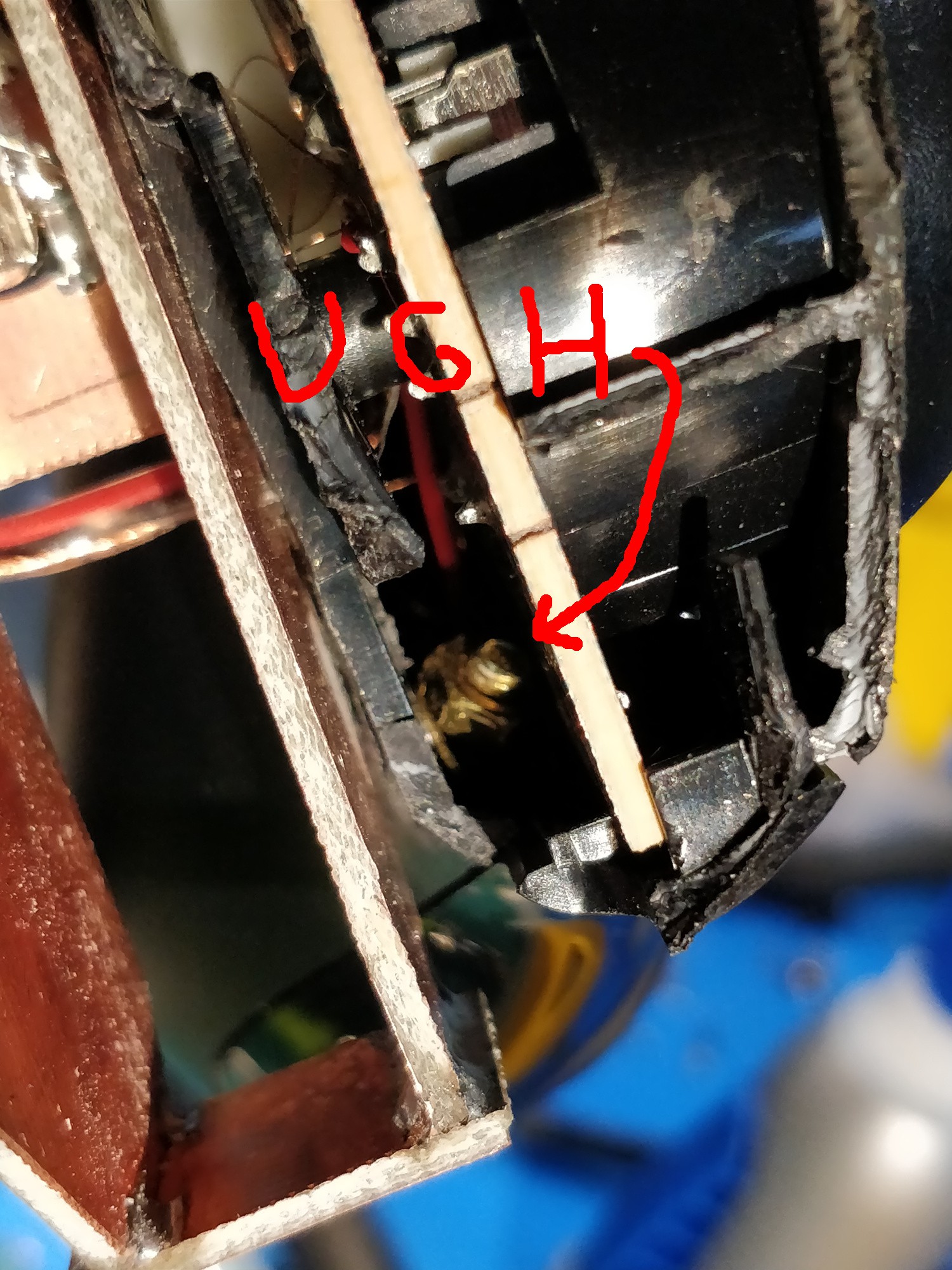

 above, a bit of space glue squeezed out between the FR4 and the ABS controller shell. Also note the continued heatshrink tube for the button signal wires.
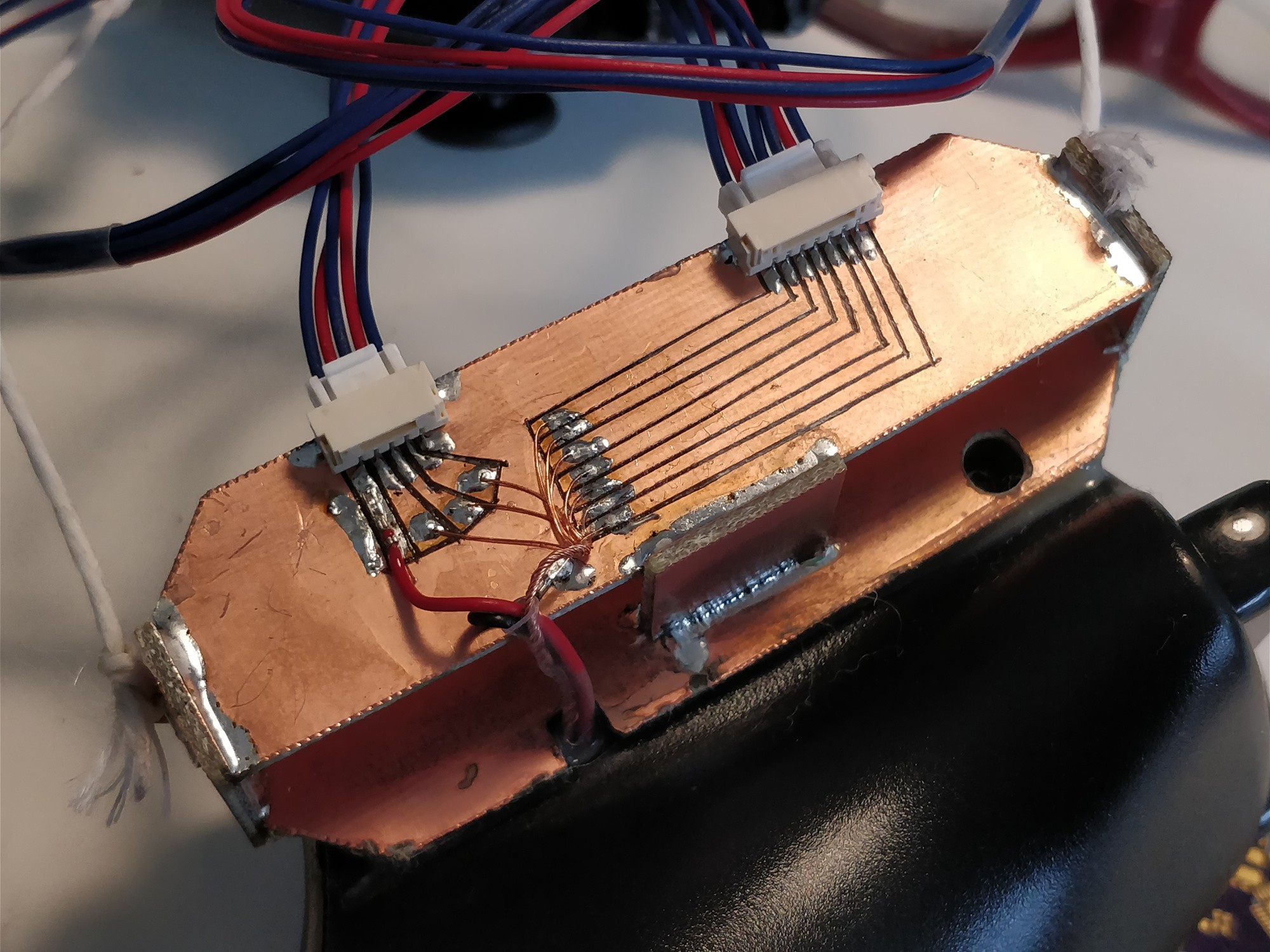

 Above, another nicely labelled PCB. R1 and R2 are for CC-1 pulldown and pullup, so this board can actually be used for a host or device. I ended up having to swap the resistor for a 5k one, otherwise 5V didn't appear on the VBUS line. Yeah I don't really want to read the USB-C spec, but this seemed to work.
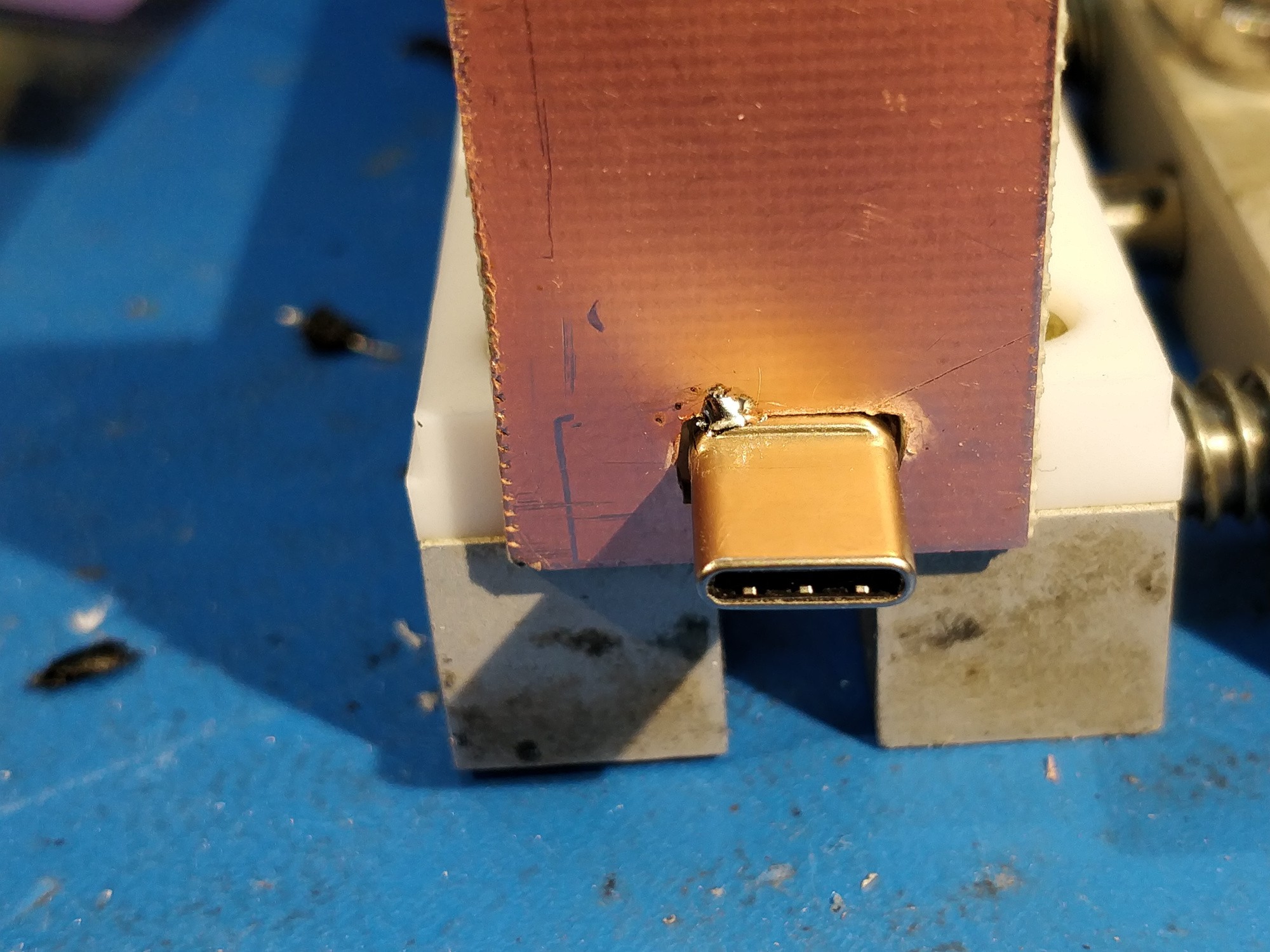


 Above, some time ago I played around with KiCad footprints for a set of replacement rubber dome elements I found on eBay. These particular parts were designed as generic drop-in replacements for SNES gamepads; enough sellers were around (and enough knockoff SNES controllers are still produced) that I thought this could be a good starting point (or, alternatively, I could use a handful of solderable rubber-dome switches and make my own arrangement). The footprint itself hasn't been tested and I'd like to round off the edges of the spiral traces, but if made with ENIG finish it should get the job done.
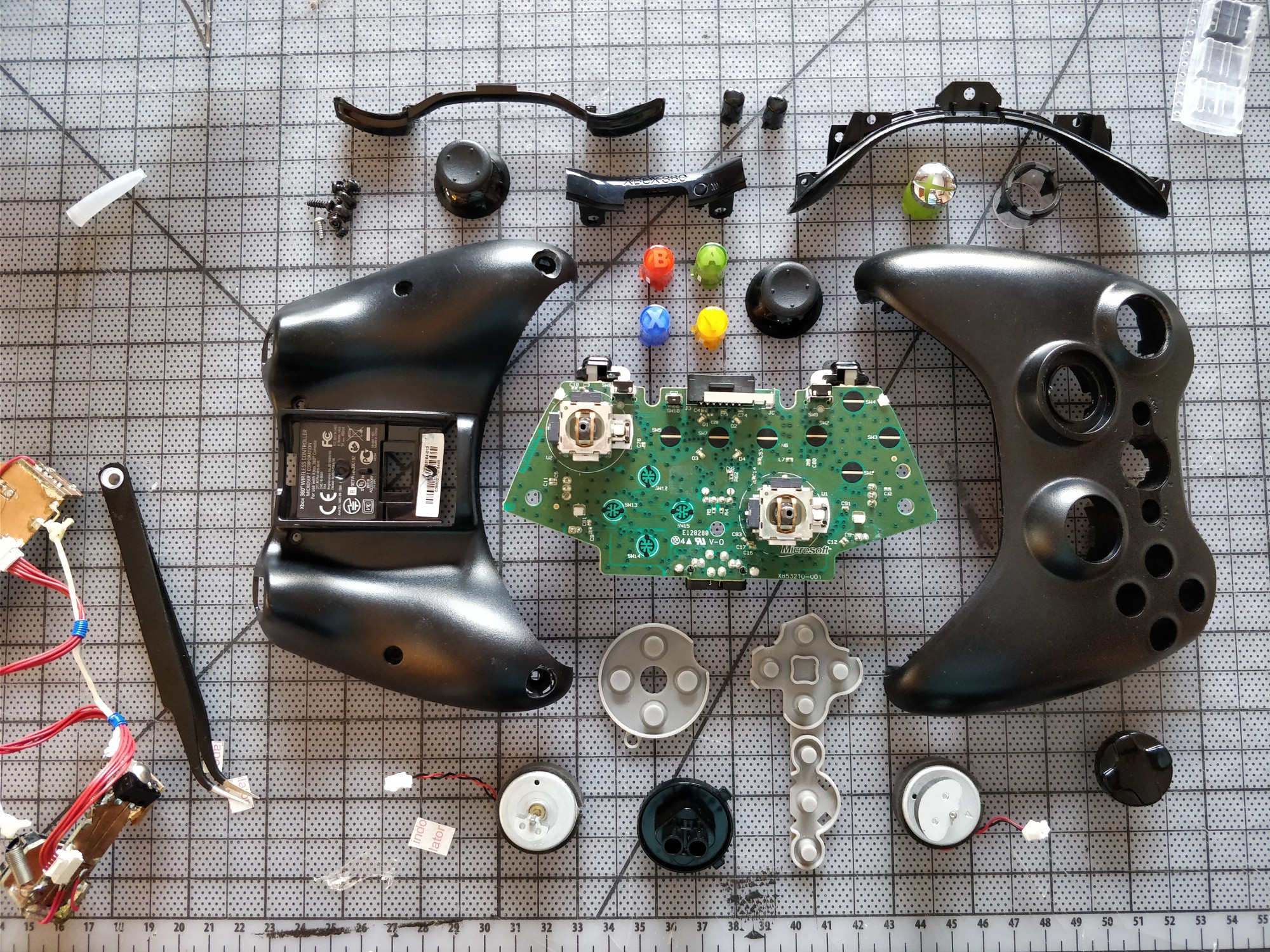
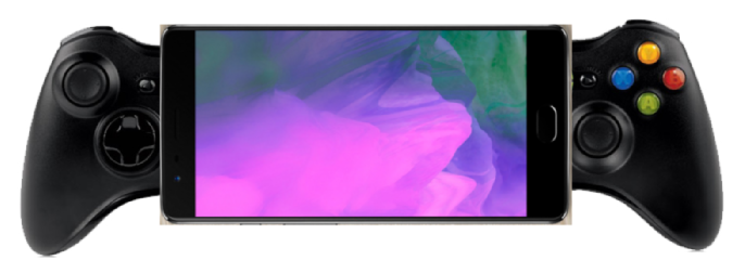 Uhh, yeah, you get the idea. Something like the 'render' above, but I'll probably be a bit more clever with the layering so the phone's top and bottom bar are under the joysticks and the controls are a closer together. I'll likely shoot for a 16:9 aspect ratio and will try to make the whole thing removable, but no guarantees there -- it may be easier to just build it into a cheap off-the-shelf case for the phone and use a wire to plug in the USB-C port.
 The PCB isn't FR4; it seems like some cheaper composite. With any luck it will survive the hot air treatment. The wireless SoC looks pretty proprietary; even the SOIC-8 to the left of the main processor is laser-etched 'XBOX'. My guess is that the latter chip is an EEPROM and the former is a slightly customized off-the-shelf microcontroller with an onboard radio, but I'm not interested in playing around with either as even in the event of success that would make this a mostly firmware exercise (far from my strong suit). And besides, I need to cut a section out of the PCB to keep the joysticks as close to the screen as possible. And even without a datasheet I can tell that the microcontroller wouldn't survive a trip through the band saw.
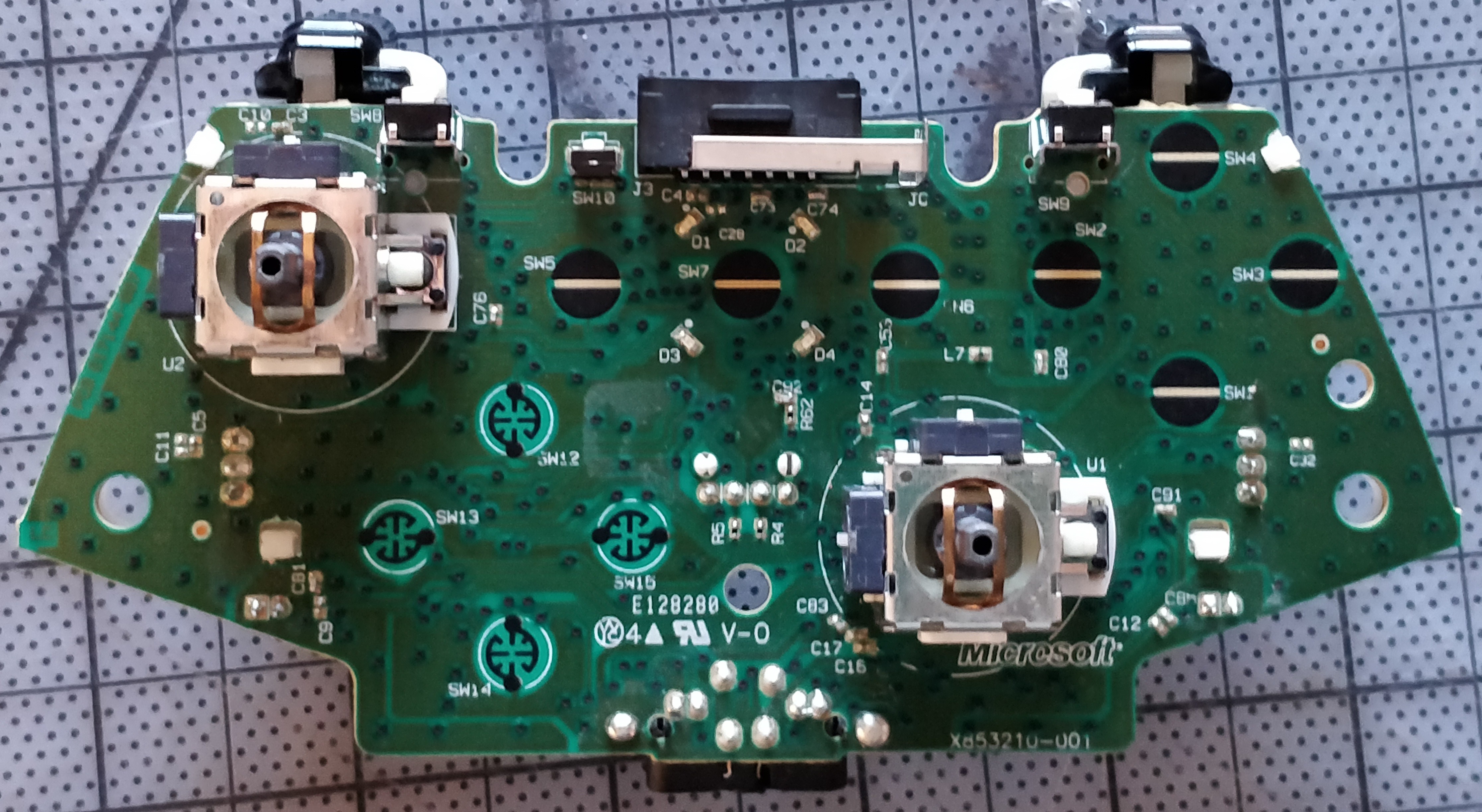 The rear of the controller PCB shows the membrane button traces and a few mounting details. I don't need anything between the D-pad (marked 'SW12 - 15' above) and the right joystick, so I'd like to cut that PCB region out entirely. The hole in the middle (above the 'V-0' silkscreen) is one of half a dozen mounting points for the PCB and probably plays a big role in preventing PCB flex when the controls are used; my planned cut eliminates this hole, so I'll need to shore the board up elsewhere.