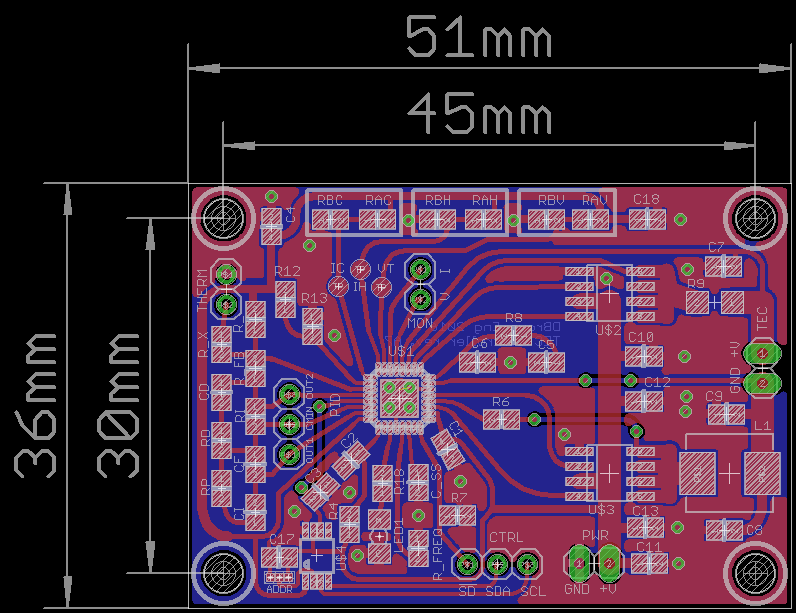
I've spent a little time revising the board to be single sided. There is little change in the overall dimensions, but I have standardised the locating holes as can be seen below.
I've switched out the variable resistors for fixed value components as the limits can be more easily calculated, and the components populated, or temporary variable resistors placed.

Reviewing the calculations it looks like I was confused between the evaluation board circuit and the data sheet (they use different nomenclature in the examples). I'm happier with the new calculations.
I need to see what components on my existing board I need to change, and then re-test with PID components.
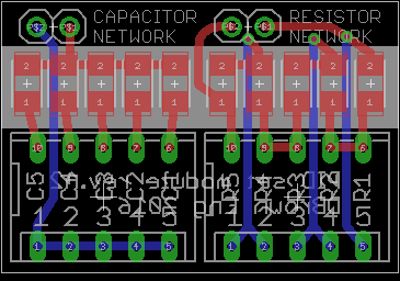
I've roughed out a quick PID component board for resistors and capacitors to help with the tuning process. This is based on the method used in the evaluation board circuit, using DIP switches to short resistors in series or switch capacitors in parallel.

 David Brown
Discussions
Become a Hackaday.io Member
Create an account to leave a comment. Already have an account? Log In.
Oh so you're still working on it, cool! You might want to pack the components on the right hand side more closely and then move everything slightly to the right - the lower left mounting hole is uncomfortably close to the traces. There should be keepout / restrict layer shapes indicating where the screw head would go. Keep it up - get it done :-)
Are you sure? yes | no
Thanks for the support, I'm going to look at substituting the controlling resistors for voltage, and current(s) limiting and the 1-channel DAC for a 4 channel option, which should clear up some space. It would be good to replace the PID network with something controllable / variable, but no idea at this point how that would be achieved. Been getting ideas from this Thorlabs 1.5A controller that was pointed out to me. [https://www.thorlabs.de/newgrouppage9.cfm?objectgroup_id=10626]
Are you sure? yes | no
I could recommend an MCP4728 (4ch 12bit I2C DAC with NVM defaults and 3 reference options (int x1, int x2, VDD). For loop configuration a PGA seems more attractive - but where do you draw the line between such a solution and a microcontroller based one? Analog Devices has very nice microcontrollers,
www.analog.com/media/en/technical-documentation/data-sheets/ADuCM360_361.pdf
24bit sigma delta ADCs and a 12 bit DAC packaged with a Cortex-M3 core. Erh, maybe that is taking this controller thing a bit too far. Still some interesting devices though.
Are you sure? yes | no