So I now have a working digitally controlled board on which PID and other control methods can be implemented. The digital portion is based around an ATTiny816 MCU and MAX5715AAUD+ 4-port DAC.
I put together the board below to convert my existing prototype. The tiny is hand soldered using standard 3mm iron tip, see Hand solder small QFNs on the kicad forum for how to do this.
I've put the code for basic control and PID up on github (see links section), i've yet to implement the I2C and serial sections to allow interactive update of set temperature and reporting of temperature, voltage and current measurements.
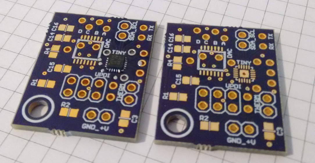
Figure: adaptor boards for ATTiny and DAC
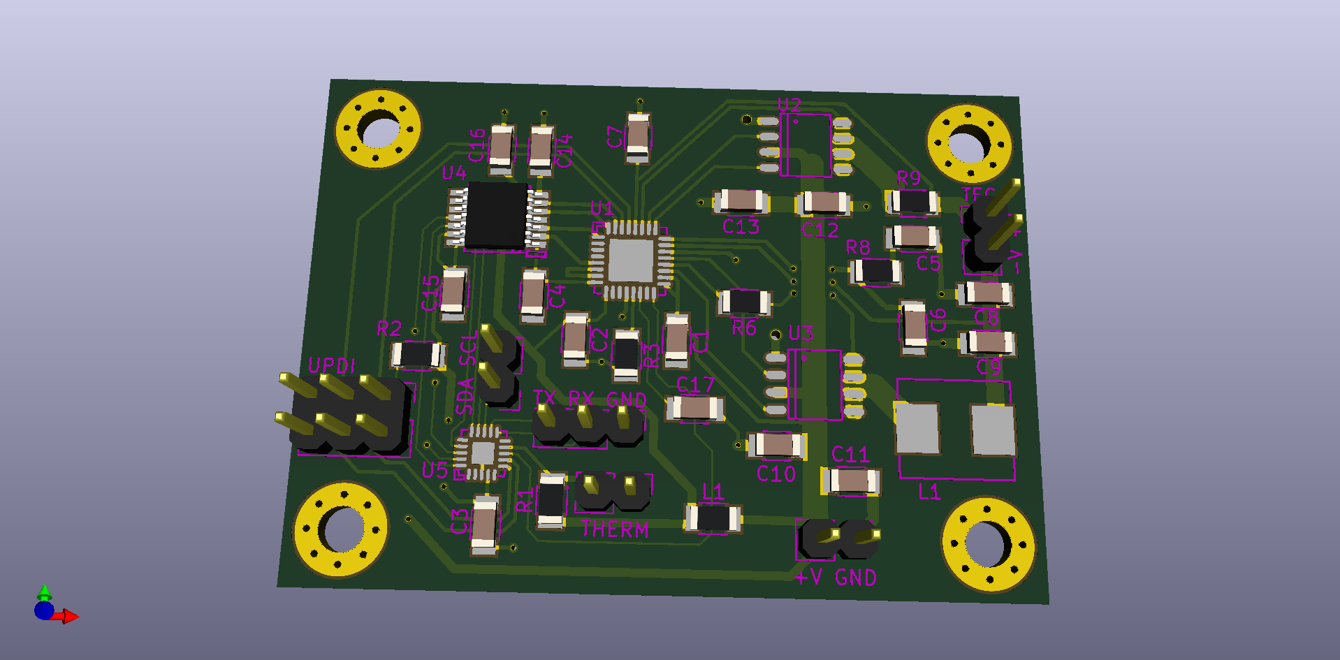
The working prototype design has been incorporated into a new board, the kicad files for which can be found in the files section. The DAC controls the maximum voltage and cool/heat current allowed, along with the control voltage to request magnitude of cool/heat required.
For testing the TEC and sensor were placed between a couple of thermal masses to allow work to be applied, the control signal and thermistor voltage were read off the scope to allow rough manual tuning of the system.
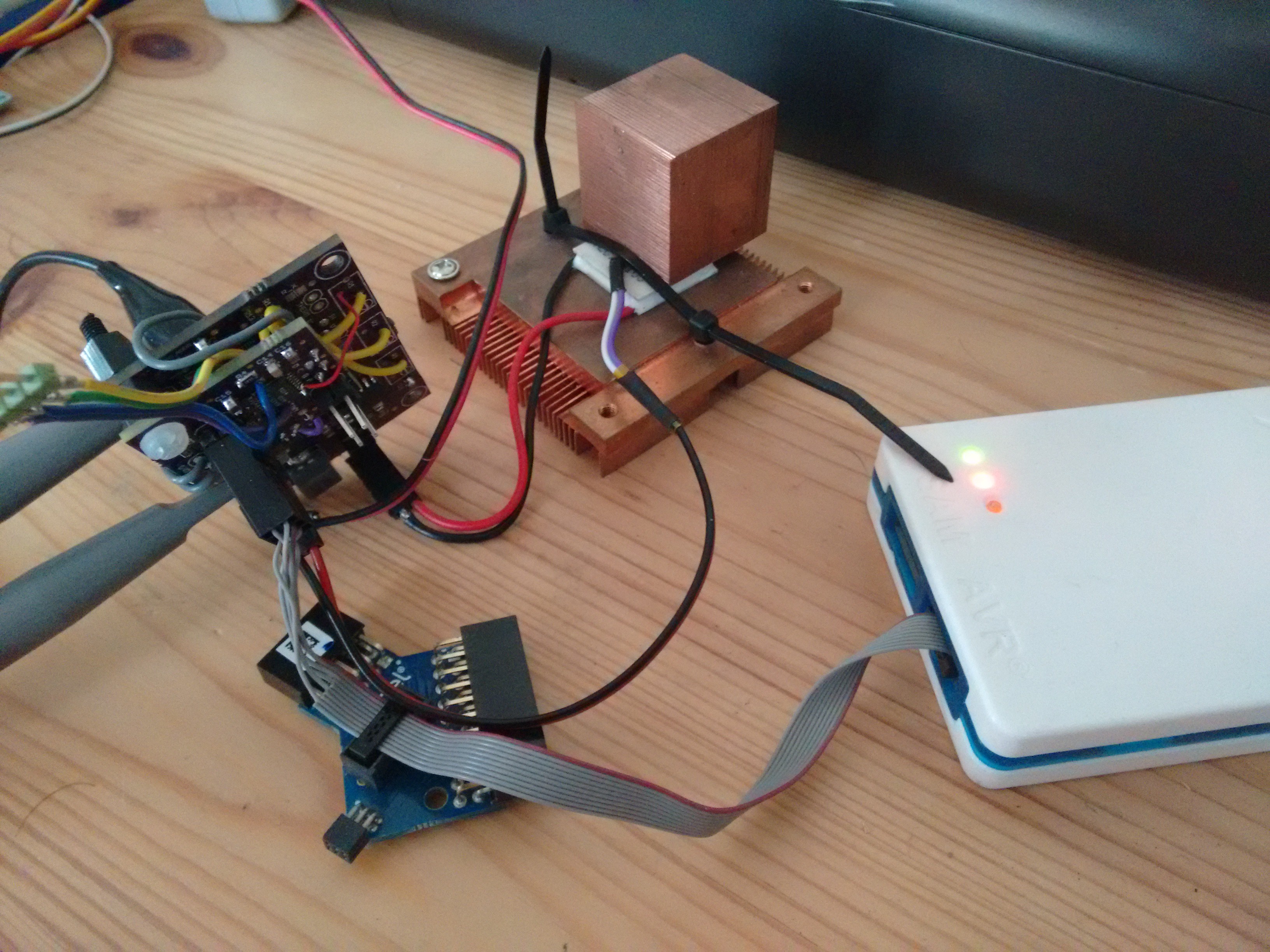
Figure: Testing setup
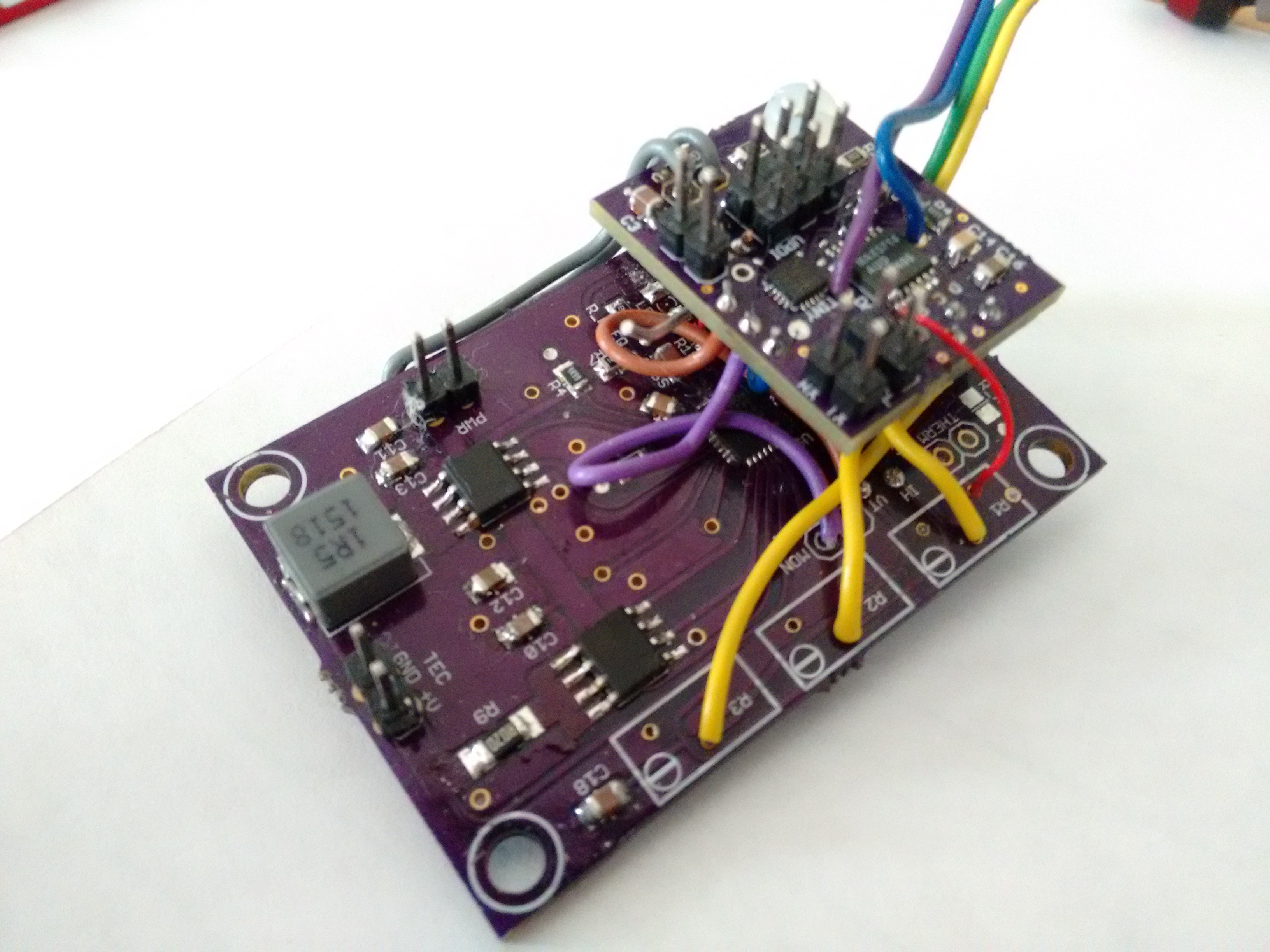
Figure: This is a view of the modified prototype (not very pretty).
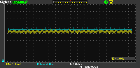
Figure: Plot showing limited fluctuations in temperature and control voltage.
 David Brown
Discussions
Become a Hackaday.io Member
Create an account to leave a comment. Already have an account? Log In.
great update!
Are you sure? yes | no