David Brown
-
Working prototype
03/20/2017 at 15:43 • 1 commentSo I now have a working digitally controlled board on which PID and other control methods can be implemented. The digital portion is based around an ATTiny816 MCU and MAX5715AAUD+ 4-port DAC.
I put together the board below to convert my existing prototype. The tiny is hand soldered using standard 3mm iron tip, see Hand solder small QFNs on the kicad forum for how to do this.
I've put the code for basic control and PID up on github (see links section), i've yet to implement the I2C and serial sections to allow interactive update of set temperature and reporting of temperature, voltage and current measurements.
![]()
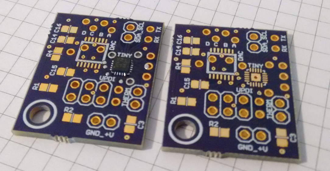
Figure: adaptor boards for ATTiny and DAC
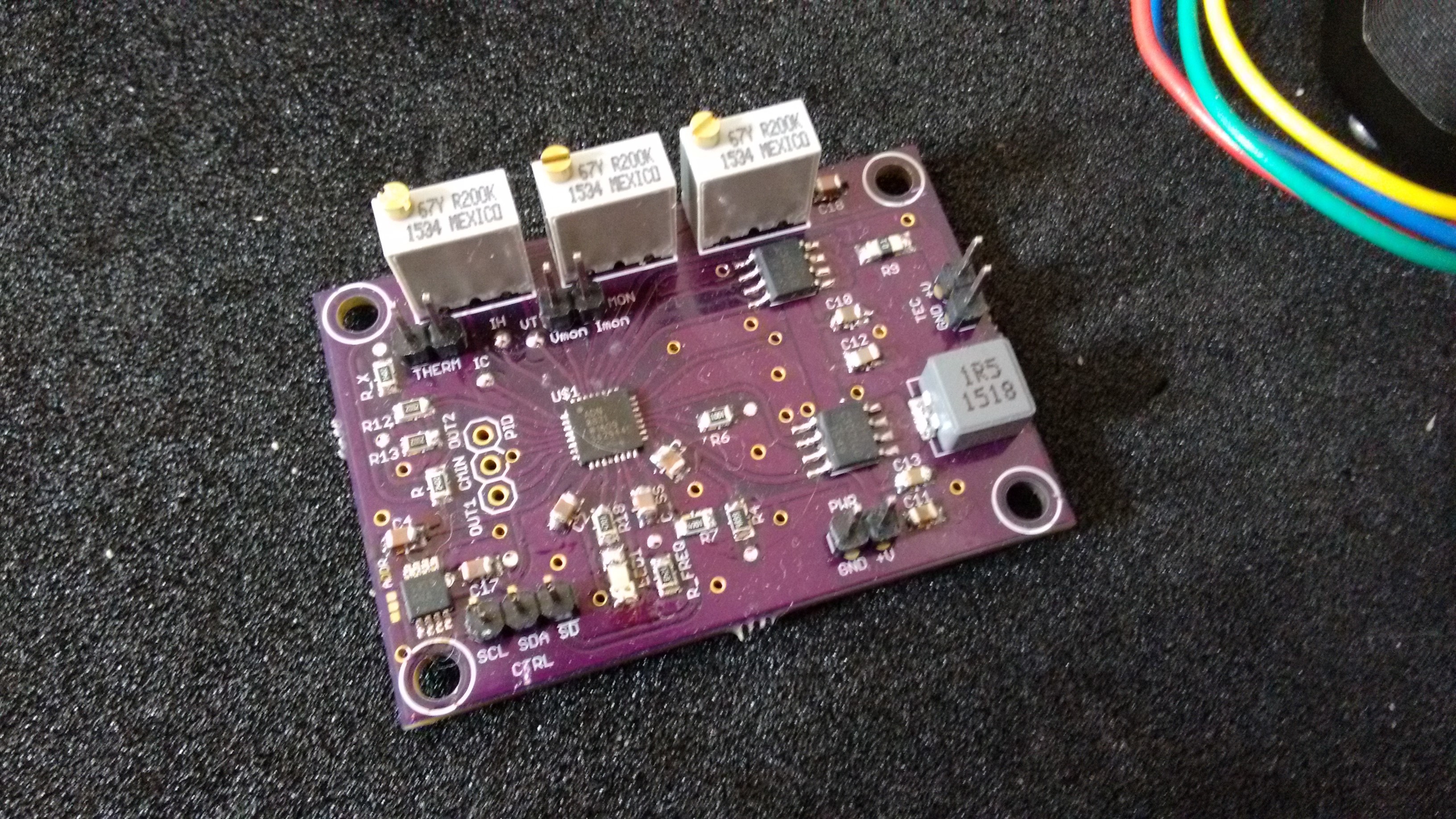
The working prototype design has been incorporated into a new board, the kicad files for which can be found in the files section. The DAC controls the maximum voltage and cool/heat current allowed, along with the control voltage to request magnitude of cool/heat required.
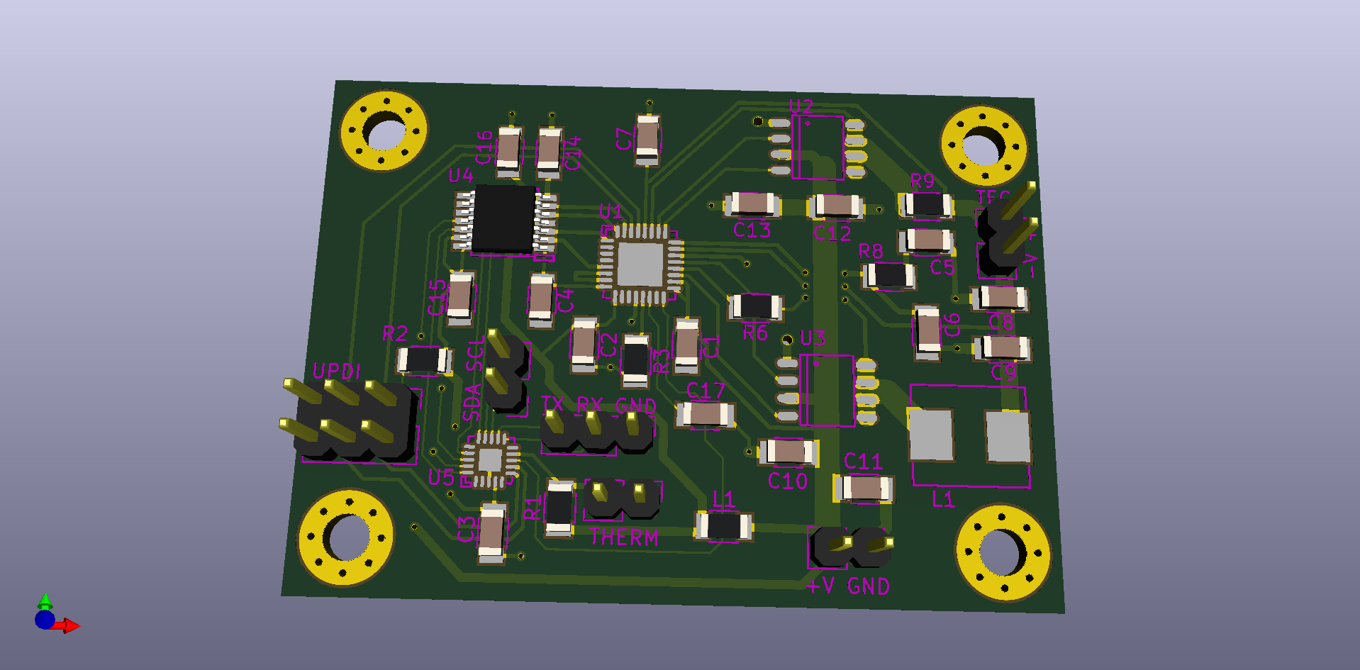
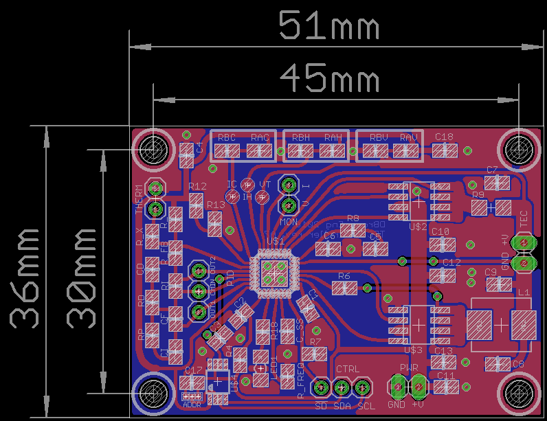
Figure: The new board design Rev. A8 / v2.0![]()
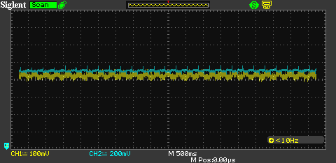
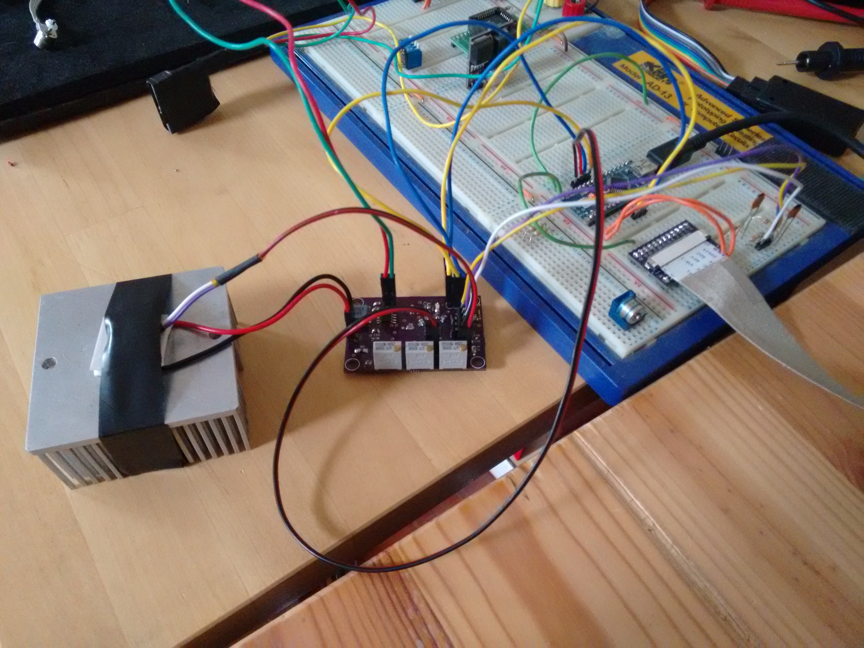
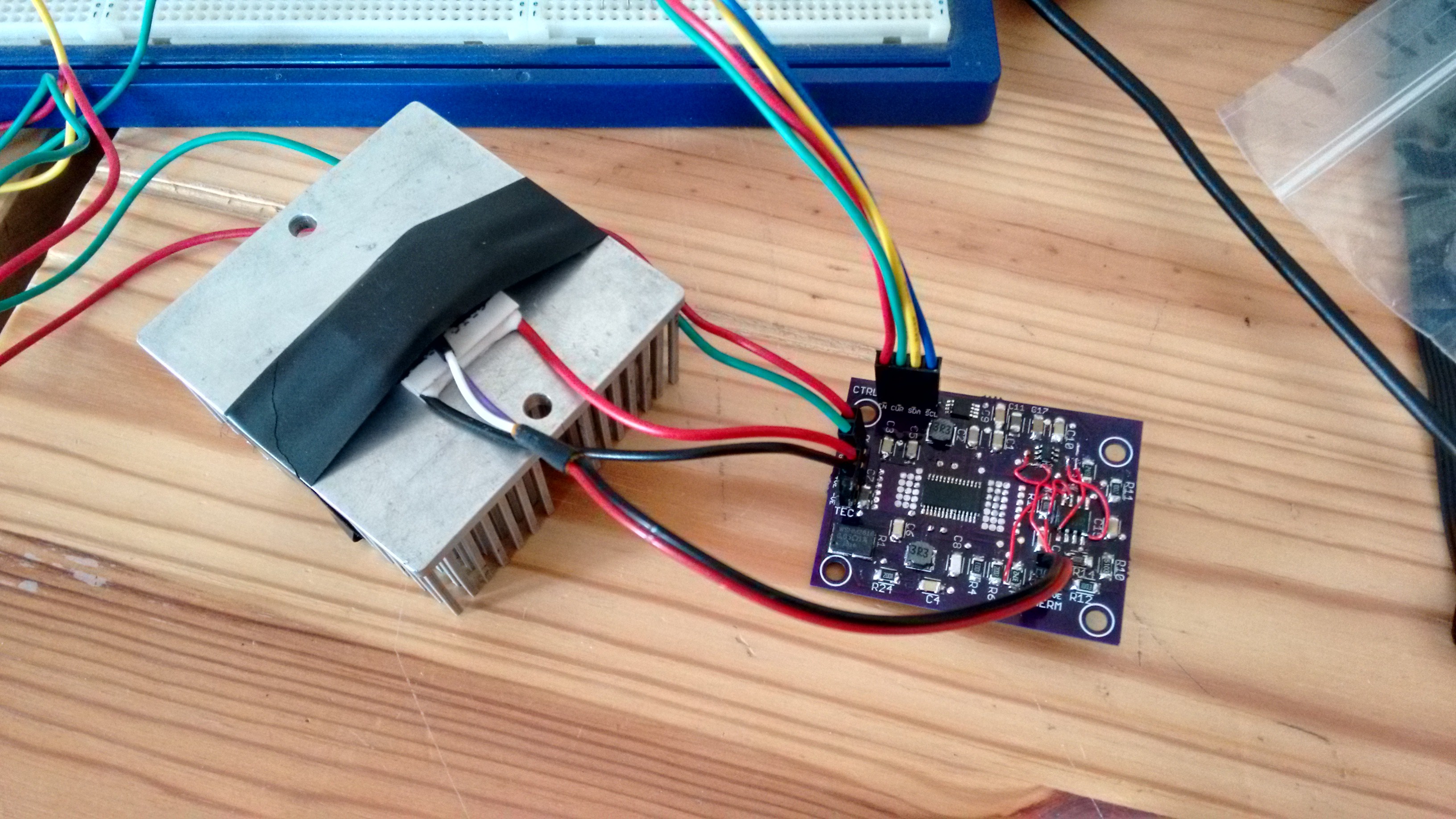
For testing the TEC and sensor were placed between a couple of thermal masses to allow work to be applied, the control signal and thermistor voltage were read off the scope to allow rough manual tuning of the system.
![]()
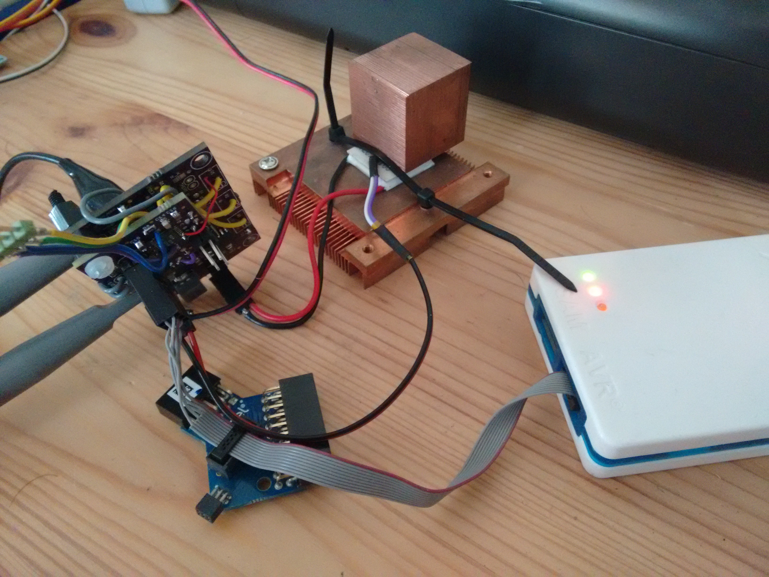
Figure: Testing setup
![]()
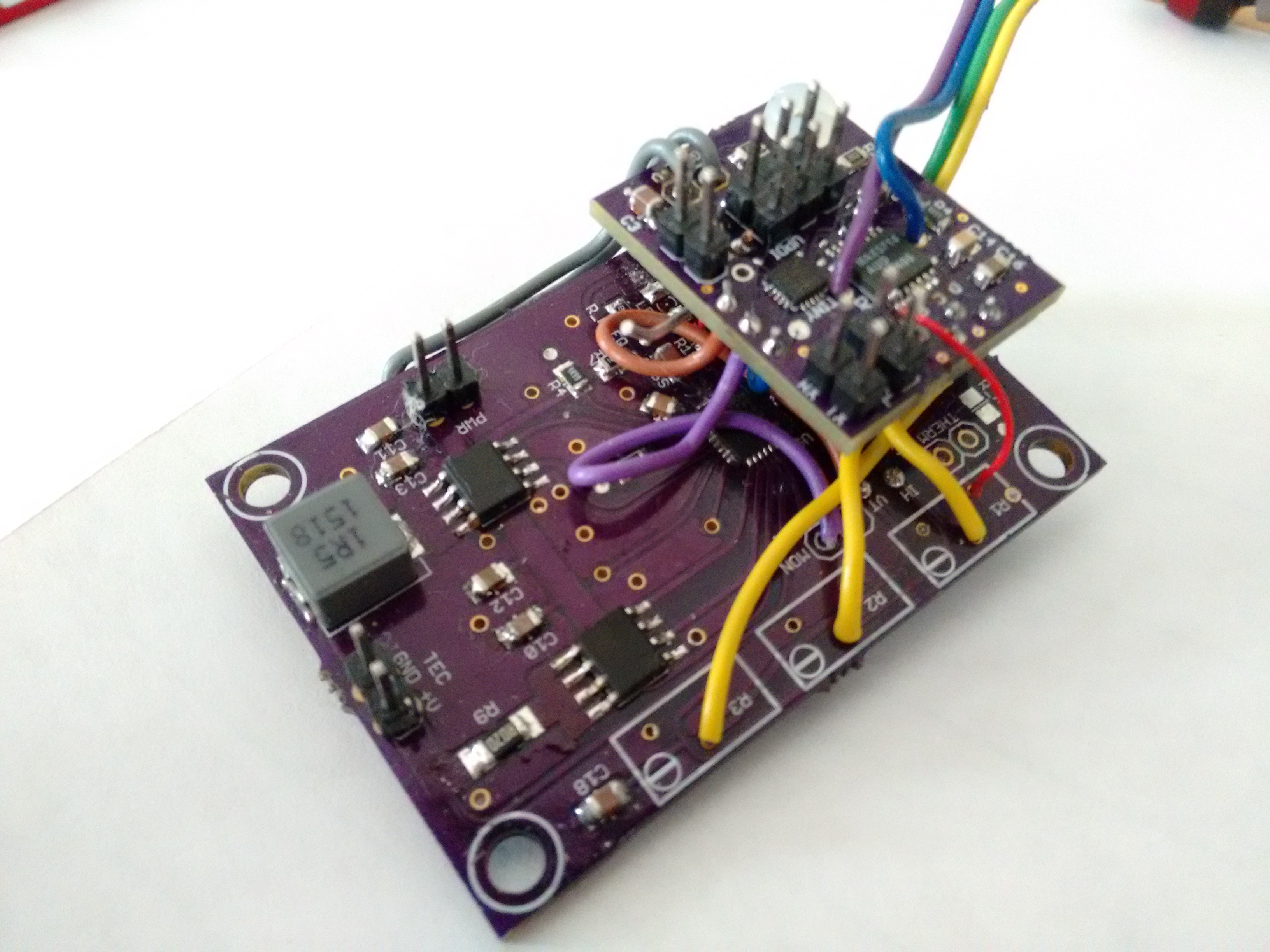
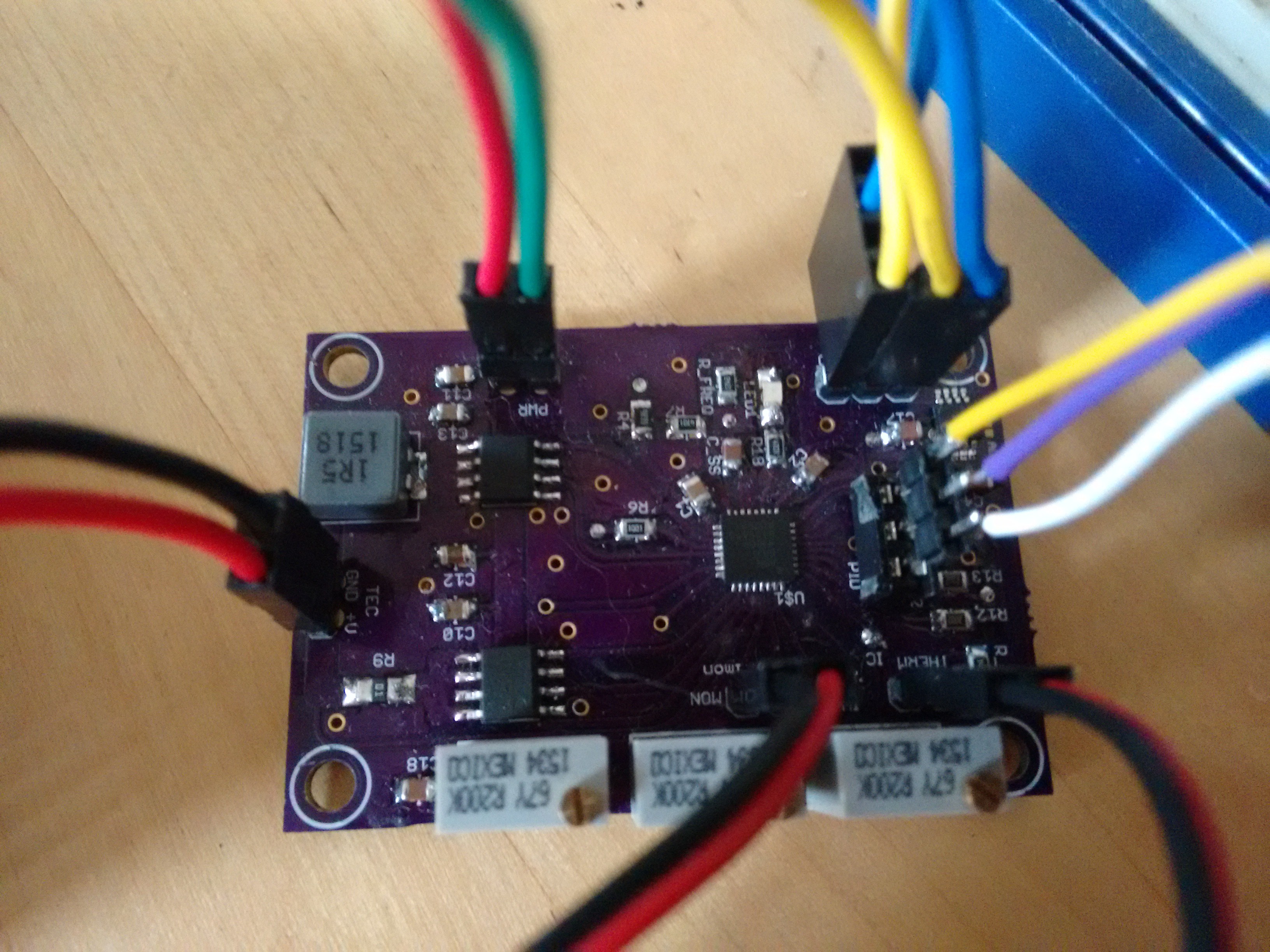
Figure: This is a view of the modified prototype (not very pretty).
![]()
Figure: Plot showing limited fluctuations in temperature and control voltage.
-
Fully digital TEC controller possible?
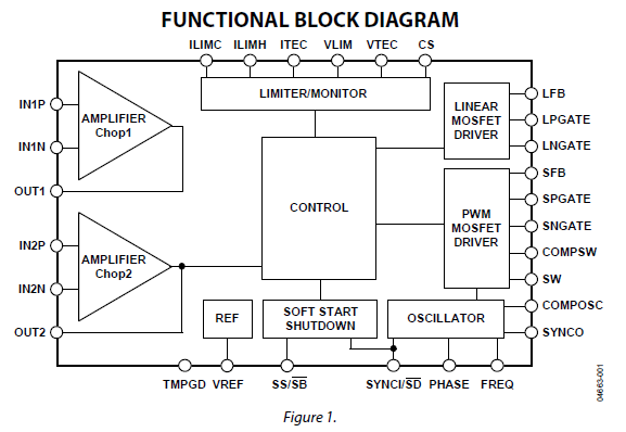
12/24/2016 at 00:08 • 0 commentsReviewing the TEC chip data sheet, it looks like it should be possible to swap out the resistor dividers and PID network components for an ATtiny (I2C slave) and x4 DAC (SPI). A thought triggered by seeing this module from Thorlabs OEM Temperature Controllers in SMT Packages.
The voltage and current limiting functions can be accomplished using a DAC to set them (ILIMC, ILIMH & VLIM), with the last channel controlling the output (OUT2).
This would allow the PID to be carried out in software and allow an adaptive algorithm to fit the thermal behaviour of the controlled mass. The controler has a linear response for control voltage of 0.25V to 2.25V for control signal of +5V to -5V on the TEC.
Voltage, current, status & temperature monitored by the ATtiny 12bit ADC, which should have sufficient resolution?
![]()
I'm looking at the ATTINY816 (at $1.06) and MAX5715AAUD+ (bit pricey at $5 in singles)
-
Revised board - rev A7
12/22/2016 at 17:05 • 3 commentsI've spent a little time revising the board to be single sided. There is little change in the overall dimensions, but I have standardised the locating holes as can be seen below.
I've switched out the variable resistors for fixed value components as the limits can be more easily calculated, and the components populated, or temporary variable resistors placed.
![]()
Reviewing the calculations it looks like I was confused between the evaluation board circuit and the data sheet (they use different nomenclature in the examples). I'm happier with the new calculations.
I need to see what components on my existing board I need to change, and then re-test with PID components.
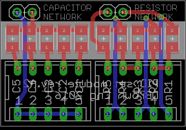
I've roughed out a quick PID component board for resistors and capacitors to help with the tuning process. This is based on the method used in the evaluation board circuit, using DIP switches to short resistors in series or switch capacitors in parallel.
![]()
-
Testing new board
07/29/2016 at 18:22 • 0 commentsSo i've finally got around to testing the new board, which appears to be behaving itself well with all of the components remaining nice and cool. The PID network is quite sensitive and will require some careful evaluation. I'm spent out so this will have to wait for a while to put together a DIP switch and range of capacitors / resistors similar to that on the evaluation board.
Soldering the main chip was done using a 5mm thick piece of aluminium plate over the gas hob and plenty of light flux over the pre-tinned pads.
![]()
I discovered one minor error which was the value of one of the resistors should have been 50k rather than the 4.7k that I had it at. I've updated the calculations and schematic / parts list to reflect this. I may also need to replace the DAC as the output is sawtooth with variation of about 0.25v which it realy should not be doing.
[Edit. replaced the DAC and output persists, no issues with the reference input voltge which is nice and stable. Looking again at the circuit the voltage is a function of both the DAC and the feed-back in the op-amp in the controller. So I think that was a false alarm on my part. Further playing shows that the PID elements are very sensetive and really do need optimizing on the actual hardware.]
Test setup; TEC, thermistor and heat sink plus connections to Arduino for control and monitoring of current and voltage signals
![]()
![]() View showing yellow, purple and white wires from the socket that allow remote prototyping of the PID elements
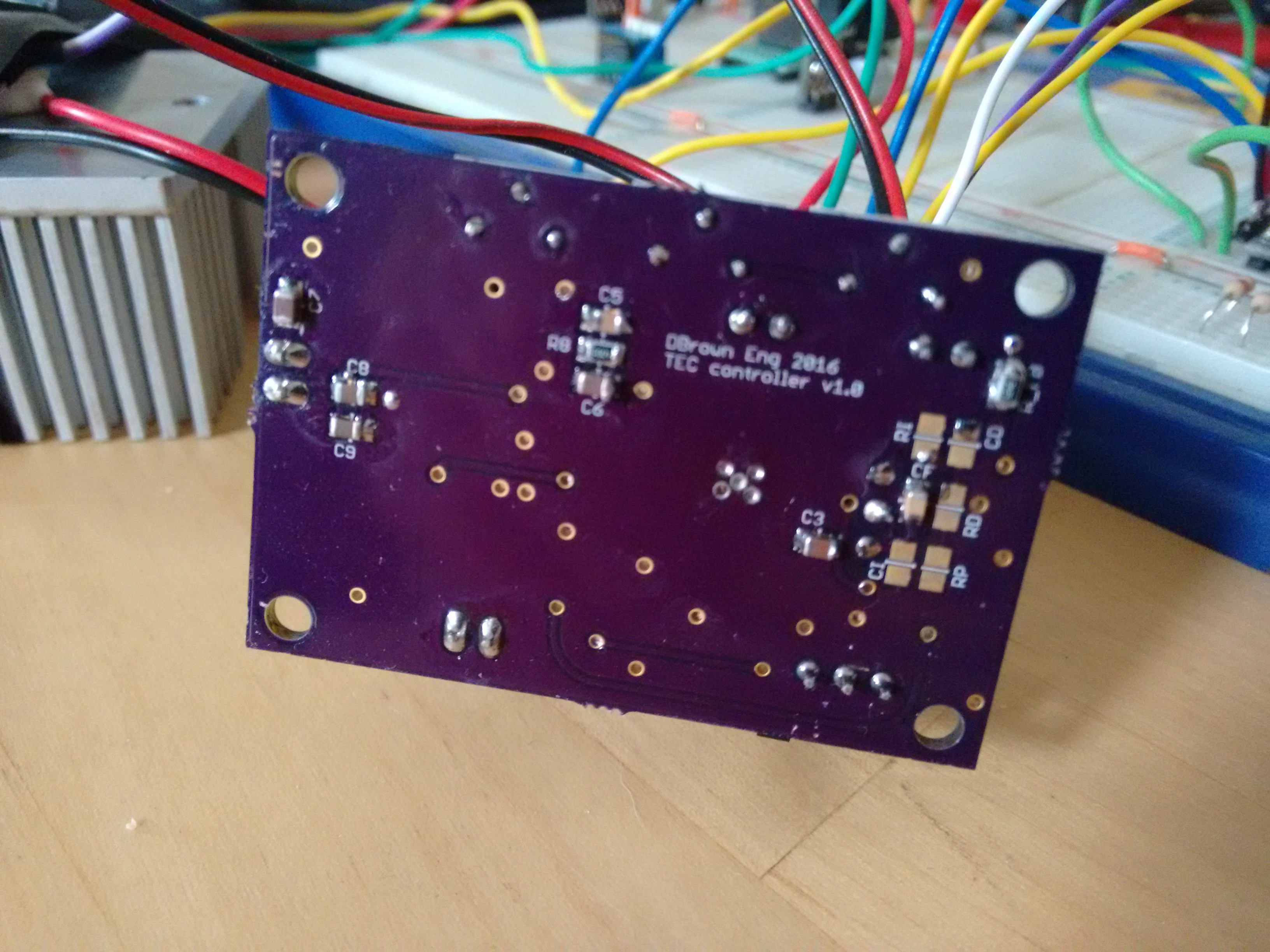
View showing yellow, purple and white wires from the socket that allow remote prototyping of the PID elements![]() Underside showing unpopulated PID components for when the correct values have been established.
Underside showing unpopulated PID components for when the correct values have been established. -
Back to the drawing board
05/08/2016 at 00:39 • 0 commentsAfter running a long test with the thermistor away from the TEC and the TEC between two heat sinks. So that the board was running at the current set limits. I found that the PCB heated up a lot, probably more heat than the TEC itself was producing. Due to the heat the op-amp system flipped, so that the it was no longer trying to cool, but was now heating.
The heat generated by the chip, suggests significant inefficiencies, this coupled with the cost of the chip itself ($45 from mouser, $20 for 2 on ebay), i've decided to work on a alternative.
I've chosen the Analog Devices ADN8831 TEC controller that works with external MOSFET H-bridges, so that I can use more recent, higher efficiency components. The controller is also priced at ~$10 for single units so is a more economic prospect.
AD have also provided guidance for using this controller for higher voltage TECs by simply using voltage level converters to connect with the H-Bridges (not required for my application).
-
v1.0 shake down
05/05/2016 at 21:33 • 0 commentsFinally received the last op-amp from mouser, which has allowed me to run tests on the board. After a number of air-wires to sort silly mistakes the board is working as expected. I will post the TINA model of the op-amp circuit that is useful for checking the feedback / set-point system.
The TEC ic runs quite warm, this may be due to having it connected to a 1A supply, rather than the 3A it will be getting. I know that from other peoples experiences that current limiting the supply can result in dead chips.
The DAC is behaving correctly, although I need to look into setting it to default to mid value at startup; 0.75v which corresponds to ~25'C. This ensures that if there errors in control and the unit is enabled before the DAC is set that the TEC should not be put into over-drive heating.
I've updated the board to fix errors and add selector for DAC address and optional components - variable resistor instead of the DAC, to allow manual temperature setting, without need for Arduino etc.
![]()
Fig. test setup, heatsink on hot side, thermistor under foam on cold side
I2C TEC controller
3A TEC controller for thermal control of laser diodes etc.