Aron Molnar
-
Our article has been published!
12/24/2016 at 21:51 • 1 commentOur article about the project has just been published in the Journal of Magnetism and Magnetic Materials!
Thank you for your support!
http://www.sciencedirect.com/science/article/pii/S0304885316322703
![]()
-
Detecting the Moon!
10/09/2016 at 01:36 • 1 commentIf the sensor is truly can reach that high resolution and sensitivity, it's theoretically capable of detecting the gravitational effect of the Moon.
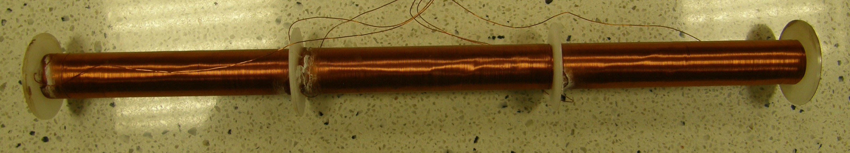
To test the theorem I made a Linear FCDT especially for this experiment. This sensor should have a big L/R ratio (L: length of one coil, R: radius of the cell) (whys explained in this log: https://hackaday.io/project/11225-a-new-high-accuracy-tilt-sensor/log/46957-theoretical-background-of-the-linear-fcdt), and extremely symmetrically winded secondary coils. I made a sensor that has an L/R ratio of 20 or so: it's 196 mm long, the cell's inner diameter is 6 mm, has 5 layers of 0.25 mm coil wire in each coil, and looks something like this:
![]() To get reliable data from the sensor, we have to take it to a very massive and vibration-free place and make measurements with it for at least 3 days in a row. We found the proper place at the University of Pannonia on top of a high-tech CNC machine. To make it convenient, I made a little program in LabVIEW that sends the measured data to my email address at every 12th hour for 3 days (the program's VI can be found in 'Files' section).
To get reliable data from the sensor, we have to take it to a very massive and vibration-free place and make measurements with it for at least 3 days in a row. We found the proper place at the University of Pannonia on top of a high-tech CNC machine. To make it convenient, I made a little program in LabVIEW that sends the measured data to my email address at every 12th hour for 3 days (the program's VI can be found in 'Files' section).
The measurement was started on 7th of Oct at 11:47 a.m. (GMT+2:00) and we're planning to continue it for 1,5 week.
We got some anomalies in the data, but there is one encouraging fact: we detected a little sine wave signal that got a periode of 24 hours.
This means that we almost detected the gravitational effect of our Moon!
-
Project is about to be published in a scientific journal!
10/08/2016 at 17:10 • 0 commentsThat's right! We wrote an article about the sensor and we are about to publish it in a scientific article - it's under review!
Here is a little section of the article:
![]()
-
Deduction of the Linear FCDT volume formula
10/08/2016 at 13:29 • 0 commentsIn a previous log (https://hackaday.io/project/11225-a-new-high-accuracy-tilt-sensor/log/46957-theoretical-background-of-the-linear-fcdt) I showed that in case of
tilt degrees, the volume of ferrofluid found in the (left) secondary coil is:
And in case of
tilt degrees, the volume of ferrofluid found in the (left) secondary coil is:
In this log I'm going to show you where this formula comes from.
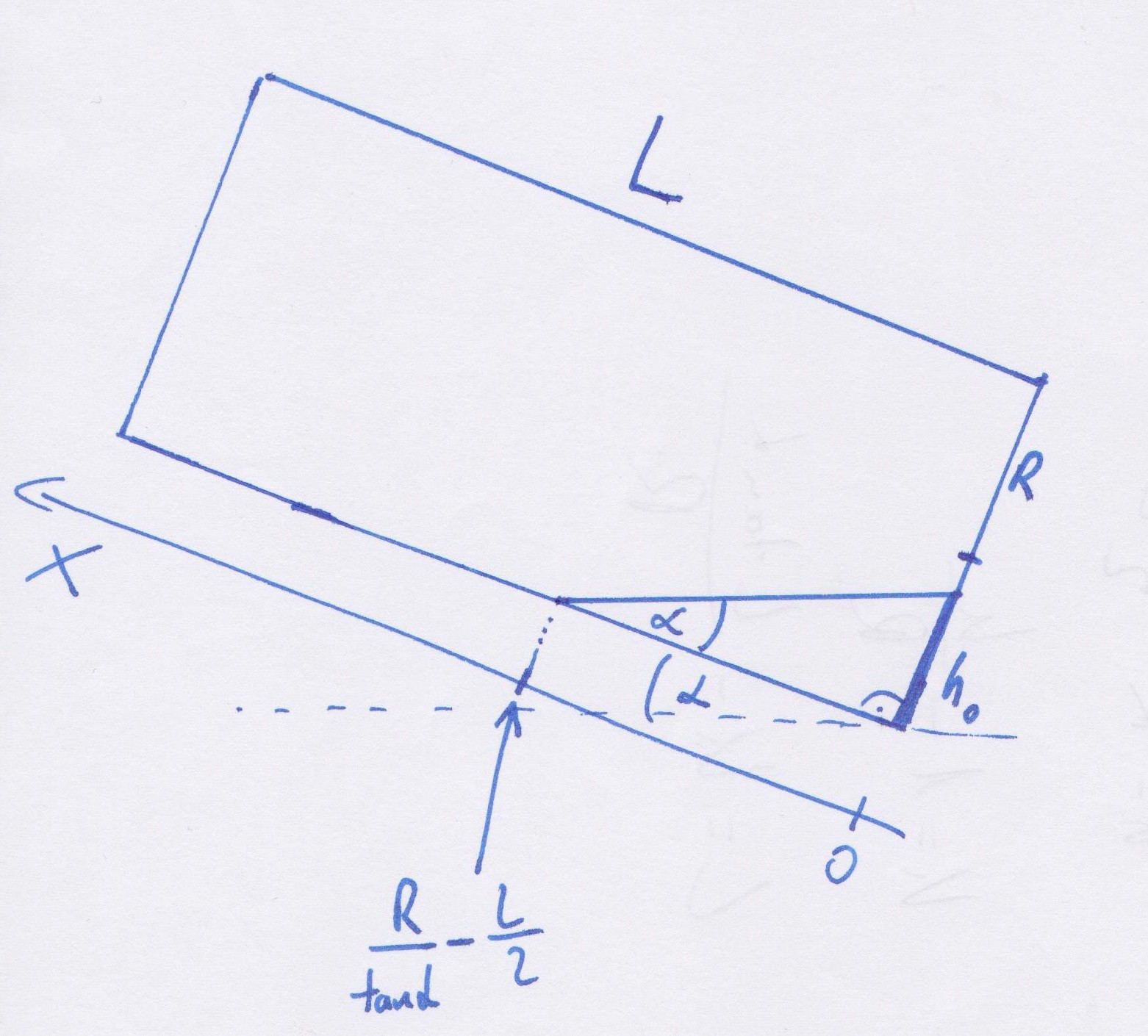
![]() First, we need to slice the sensor at a point, and calculate the area of the ferrofluid at that point. This area should only depend on values we already know, such as the alfa tilt degree, the L coil length, the R radius, and the x variable. If got the area at that point, we can integrate it along x, and we get the volume of the ferrofluid.
First, we need to slice the sensor at a point, and calculate the area of the ferrofluid at that point. This area should only depend on values we already know, such as the alfa tilt degree, the L coil length, the R radius, and the x variable. If got the area at that point, we can integrate it along x, and we get the volume of the ferrofluid.
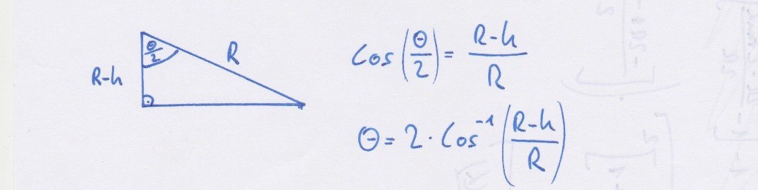
![]() According to the picture above, the area of the fluid is:
According to the picture above, the area of the fluid is:Next, we have to express theta with respect to R and h, since we only know the value of R (and we will know the value of h after the next step). We can do it using the simple angle-dependent cosine:
![]() With this, the formula of the area looks like this:
With this, the formula of the area looks like this:Now there is only one variable we don't know: h. Let's determine it!
At a chosen x, h equals to:![]()
And from the picture above, h0 is:Substituting h0 to h's equation:
And that's it! The area of a slice looks like this:In the formula, the area depend on the R radius, the L coil length, the alfa tilt degree, and the x variable. Our last thing to do is to integrate it along x, and we get the volume of ferrofluid in a coil. But note that in cases of
we integrate from 0 to L, and in cases of
we integrate from 0 to
-
Experimental and theoretical curves of the Linear FCDT
10/04/2016 at 22:00 • 0 commentsPrevious post: Theoretical background of the Linear FCDT (https://hackaday.io/project/11225-a-new-high-accuracy-tilt-sensor/log/46957-theoretical-background-of-the-linear-fcdt)
In the previous post I showed how we can calculate Vsec1, and Vsec2 with respect to the tilt of the sensor. I also pointed to that the measuring range and the sensitivity of the Linear FCDT is strongly depend on the L/R ratio. (Where L and R are shown in the previous post"s first picture.)
In this post I'm going to compare the theoretical and experimental curves of our Linear FCDT.
Our Linear FCDT was tested with the AD598 signal conditioner IC, which is used with LVDTs. The coil length of the sensor was L = 18 mm; the radius of the inner cell was R = 3 mm; the amplitude of the excitation voltage was A = 6 V; the frequency was f = 11 kHz; the M cell constant was determined using the already known dimensions of the cell, and the extreme values of Uout:
The theoretical curve was determined with the knowledge of the L/R = 6 rate, and the M cell constant:
![The experimental data and the theoretical curve of the Linear FCDT]()
-
Theoretical background of the Linear FCDT
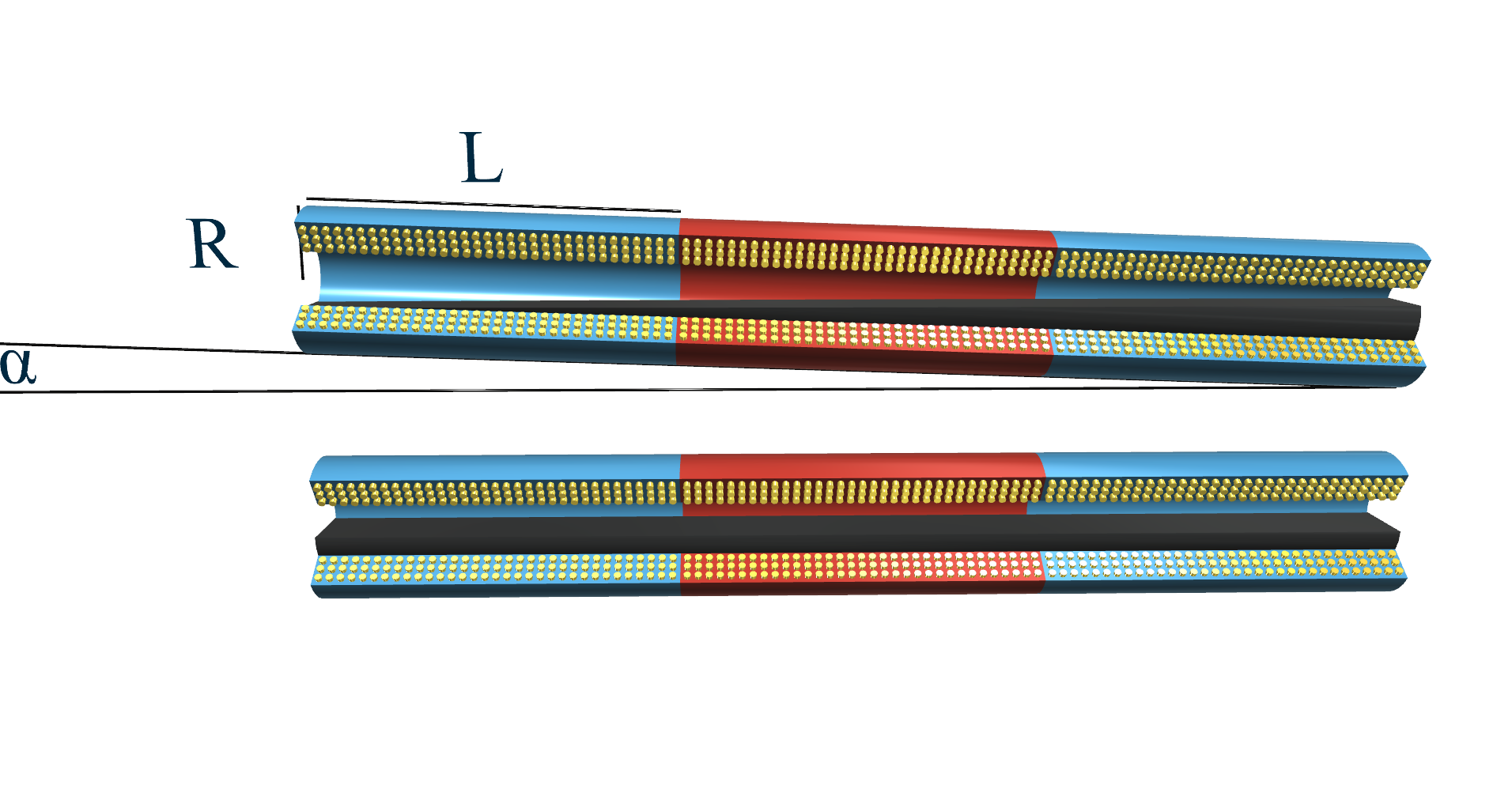
10/04/2016 at 21:54 • 0 commentsThe Linear FCDT has three coils, which take place next to each other. The primary coil is usually excited with a frequency of 1 to 20 kHz and an excitation voltage range of 1 to 24 V rms.
![The structure of the Linear FCDT]()
The cell surrounded by the three coils is exactly half-filled with ferrofluid, so there is a volume of
ferrofluid in the cell. At any tilt of the sensor, there is always a volume of
in the primary coil. The spare volume of
is divided amongst the secondary coils depending on the tilt of the Linear FCDT.
Let's check out the left secondary coil on the picture above. Starting from α = 0 °, in cases of positive α tilt, the Vsec1 amount of ferrofluid will decrease.
- In the case of
tilt degrees, the liquid level can reach the outer wall, so the amount of ferrofluid in the left coil is:
- In the case of
tilt degrees, the liquid level can’t reach the outer wall, so the amount of ferrofluid in the left coil is:
Deduction of the formula can be found here: https://hackaday.io/project/11225-a-new-high-accuracy-tilt-sensor/log/47221-deduction-of-the-linear-fcdt-volume-formula
If we plot the values of Uout normalized to 1 in cases of disparate L and R rates between -90 ° and +90 ° it is noticable that the measuring range, and the sensitivity inside that, strongly depends on the L/R rate. In cases of low rate we get a relatively great measuring range, in cases of high rate we get a smaller measuring range, but higher sensitivity.
![The effect of L/R rate to the characteristics of the Linear FCDT]()
Next log: Experimental and theoretical curves of the Linear FCDT (https://hackaday.io/project/11225-a-new-high-accuracy-tilt-sensor/log/46959-experimental-and-theoretical-curves-of-the-linear-fcdt)
- In the case of
-
Experimental and theoretical curves of the Toroid FCDT
10/04/2016 at 21:47 • 0 commentsPrevious post: Theoretical background of the Toroid FCDT (https://hackaday.io/project/11225-a-new-high-accuracy-tilt-sensor/log/46947-theoretical-background-of-the-toroid-fcdt)
Now that we know from the previous post that how to calculate Vsec1, and Vsec2, we can move on to calculate Uout of the sensor with respect to the tilt, and compare our results with the experimental data.
In this post I'm going to compare the theoretical and experimental curves of our Toroid FCDT.
The output voltage of the toroidal sensor is given in a form of
The M cell constant was determined using the known dimensions of the cell, and the extreme values of Uout,
The theoretical and the experimental curves of the sensor can be seen on the graph below:
![]()
-
Theoretical background of the Toroid FCDT
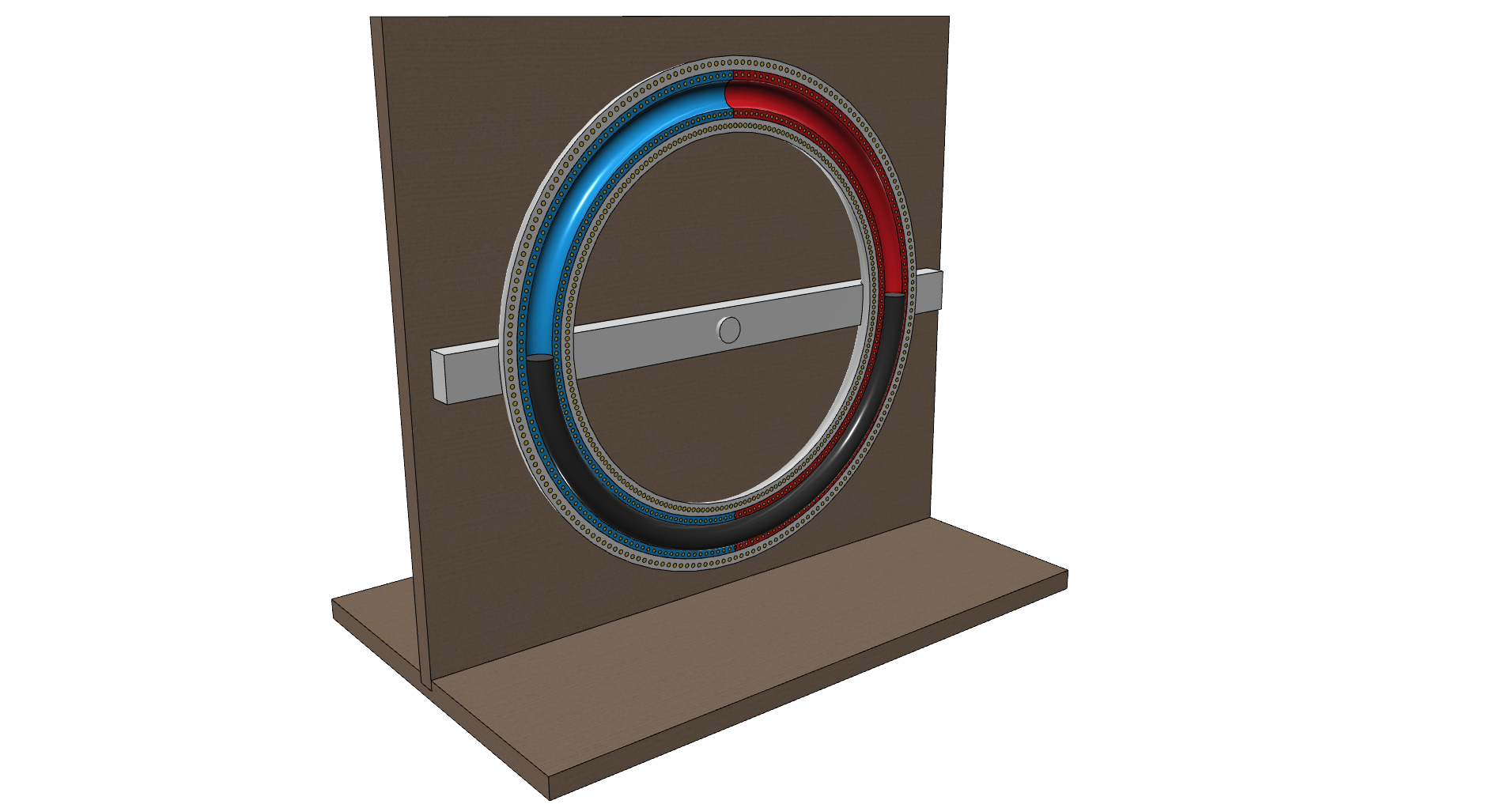
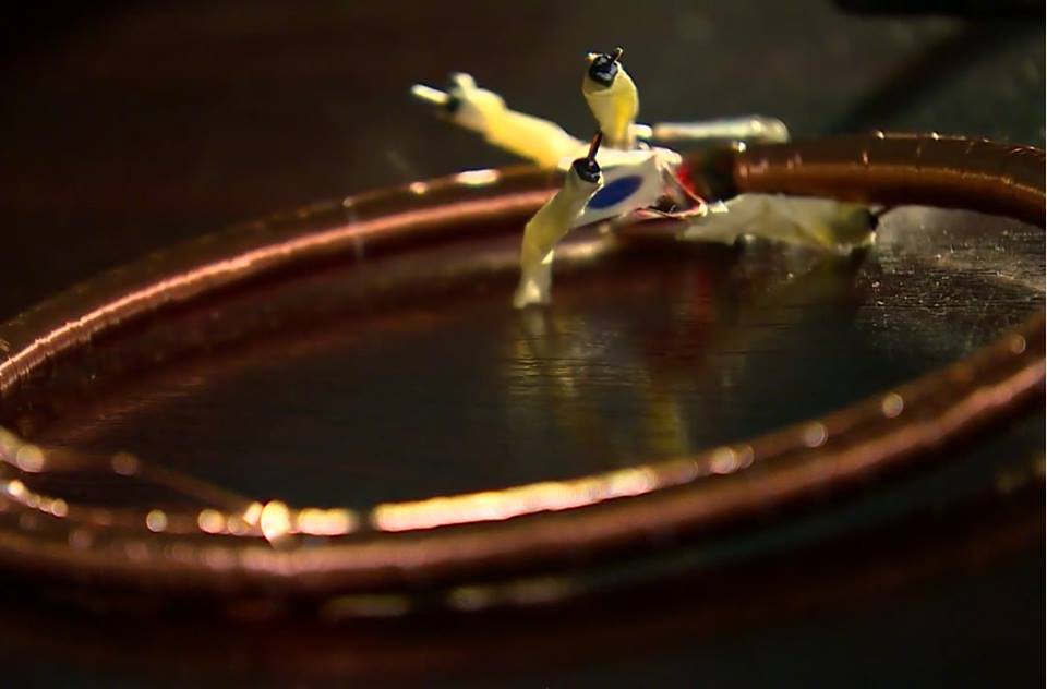
10/04/2016 at 19:07 • 0 commentsThe Toroidal FCDT is consist of three coils just as the Linear FCDT, but the coils were winded toroidal around a glass tube bent in an O-form. Each secondary coil overlays the half of the torus, and they has around 800-800 turns. The primary coil overlays the the whole torus:
![The Toroidal FCDT and the mounting]()
The external radius of the Toroidal FCDT is R = 80 mm, the internal radius is r = 3 mm. The inner cell is precisely half-filled with ferrofluid, thus the volume of the fluid in the cell is
And the volume of
ferrofluid is divided amongst the two secondary coils depending on the tilt of the sensor. It is obvious that when rotating the sensor, the amount of ferrofluid in the secondary coils is changing linearly with the tilt. In cases of α = 0 ° and α = 180 ° there is an equal volume of
ferrofluid in the secondary coils. In cases of α = 90 ° and α = 270 ° the ferrofluid is always in just one secondary coil. It can be seen on the diagram below:
![The amount of ferrofluid in the secondary coils depending on the tilt in the Toroid FCDT]()
Next post: Experimental and theoretical curves of the Toroid FCDT (https://hackaday.io/project/11225-a-new-high-accuracy-tilt-sensor/log/46956-experimental-and-theoretical-curves-of-the-toroid-fcdt)
-
3D models
09/24/2016 at 16:10 • 0 commentsWe made some 3D models about the sensors and the resolution measurement test bench just to visualize them better. Here they are:
Linear FCDT:
![]()
![]()
Toroid FCDT:
![]()
Resolution measurement test bench:
![]()
-
How the precise resolution measurements were made
09/24/2016 at 13:22 • 0 commentsI've been saying that the Linear FCDT is capable of measuring tilt with a really high resolution, but I didn't say a word about from where do I know that. I just only said that „After hours and hours of making an extremely precise measurements...”. It’s time to say a few words about those extremely precise measurements.
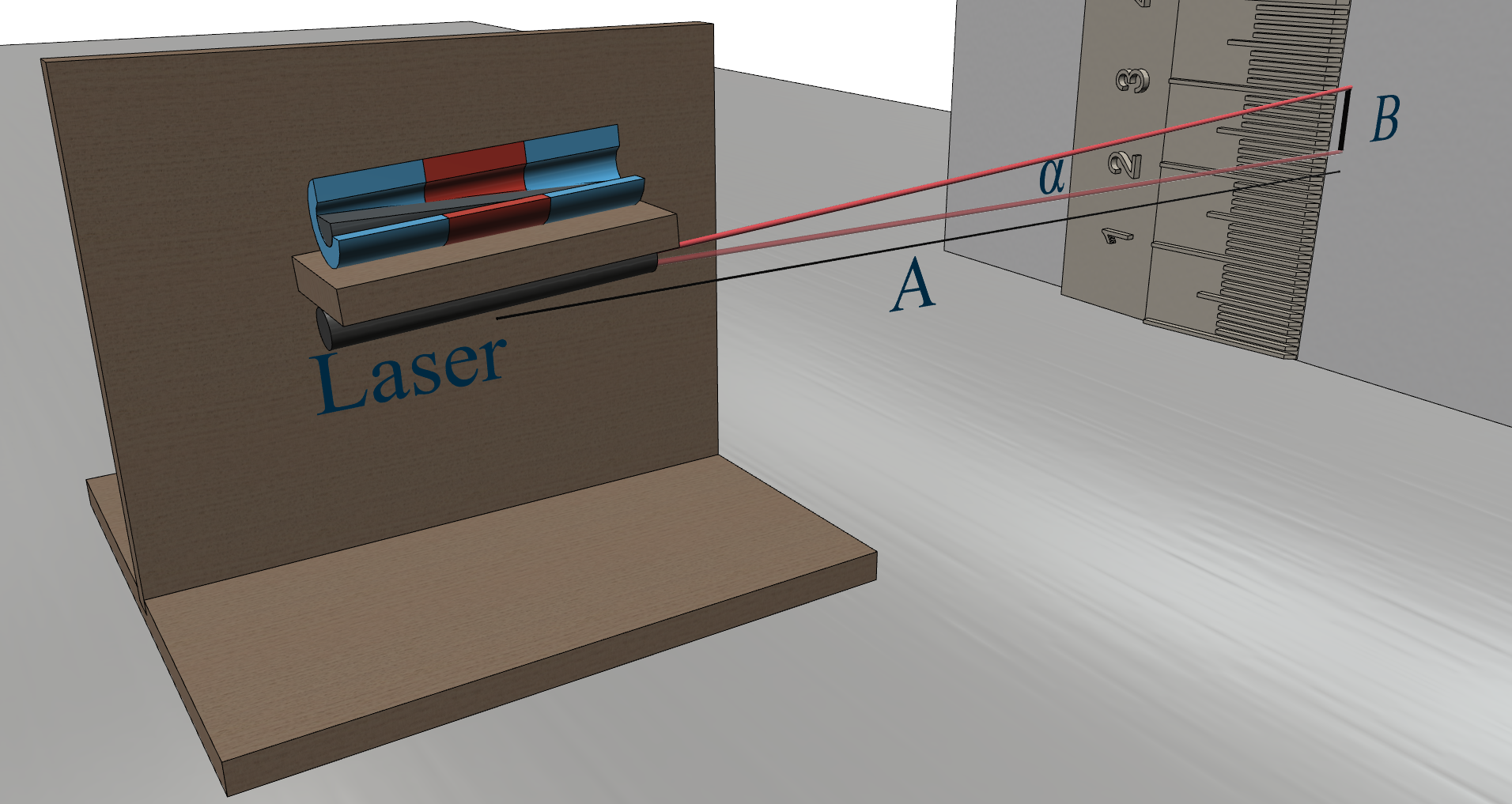
The main idea is that get a laser pointer, attach it to the test bench (picture below), adjust the bench a little bit, see how many millimeters the laser point went from the relative horizontal level on the wall (the wall-test bench distance is about 10 meters), write down the output voltage of the signal conditioner IC, compute the tilt, and do it again at least 50 times.
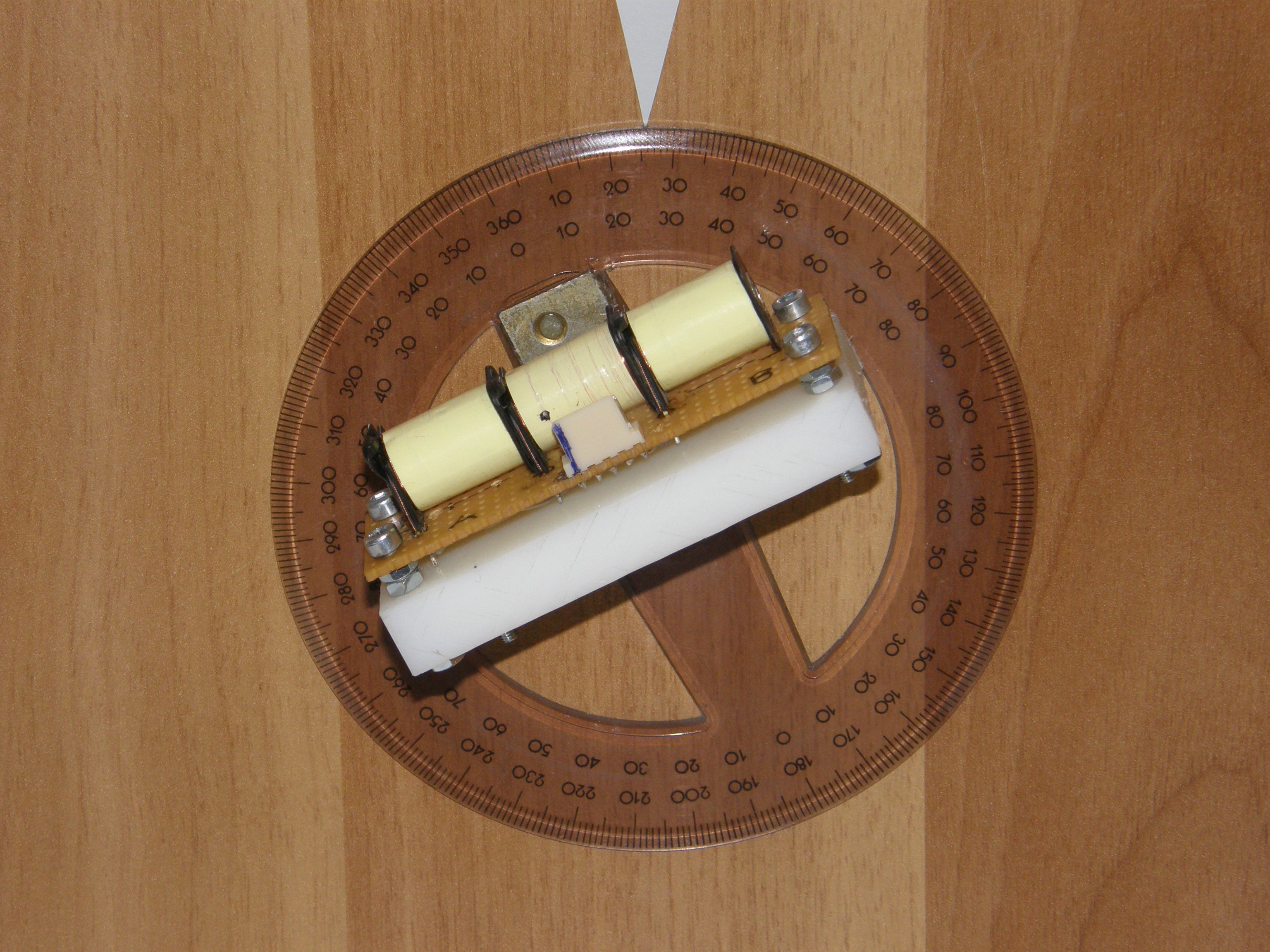
This is the test bench with the Linear FCDT (sadly, I didn’t take photos with the laser attached to it when we made the measurements):
![]()
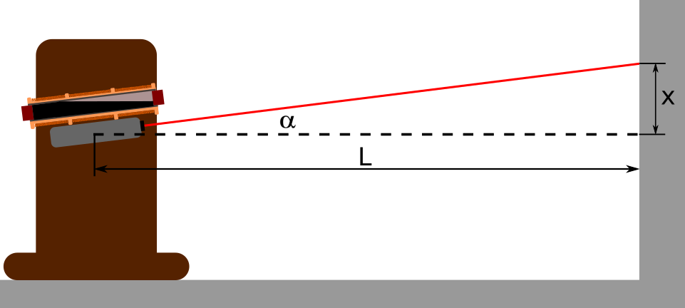
The schematic of the measurement looks something like this:
![]()
So after we tilt the sensor a little bit, the position of the laser point on the wall will change significantly, since L is great. Then we measure x, and compute the tilt with this single equation:
Next, we inspect how the output voltage of the signal conditioning circuit changed, and write down these two number next to each other: ouput of sig conditioner IC - tilt.
With this method, we can do extremely precise measurements, because L is great, so if we tilt the senor just a little bit, the chage of x will be great enough to measure that conveniently.
A new high accuracy tilt sensor
This project aims to build a tilt sensor that is cheap, very accurate and has a wide measuring range (up to 360 degrees).
 To get reliable data from the sensor, we have to take it to a very massive and vibration-free place and make measurements with it for at least 3 days in a row. We found the proper place at the University of Pannonia on top of a high-tech CNC machine. To make it convenient, I made a little program in LabVIEW that sends the measured data to my email address at every 12th hour for 3 days (the program's VI can be found in 'Files' section).
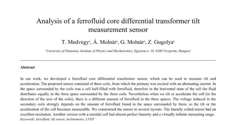
 First, we need to slice the sensor at a point, and calculate the area of the ferrofluid at that point. This area should only depend on values we already know, such as the alfa tilt degree, the L coil length, the R radius, and the x variable. If got the area at that point, we can integrate it along x, and we get the volume of the ferrofluid.
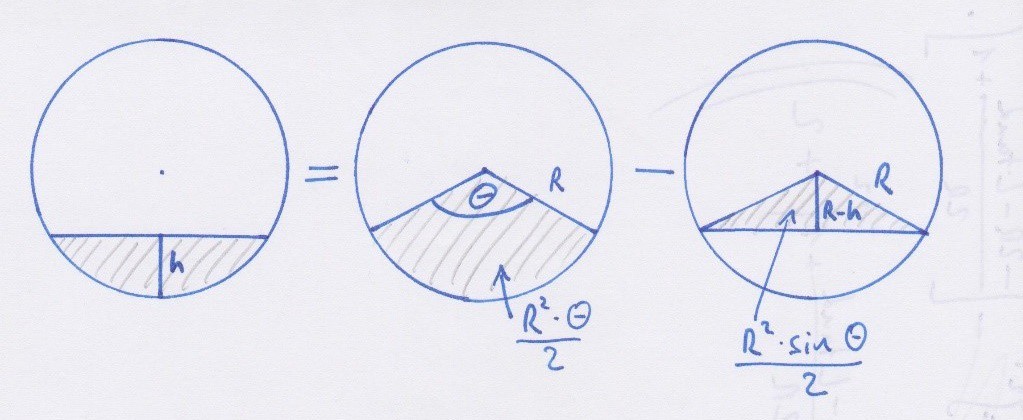
 With this, the formula of the area looks like this: