codersilver
-
Face Detection and Tracking, DCS-5020L + OpenCV
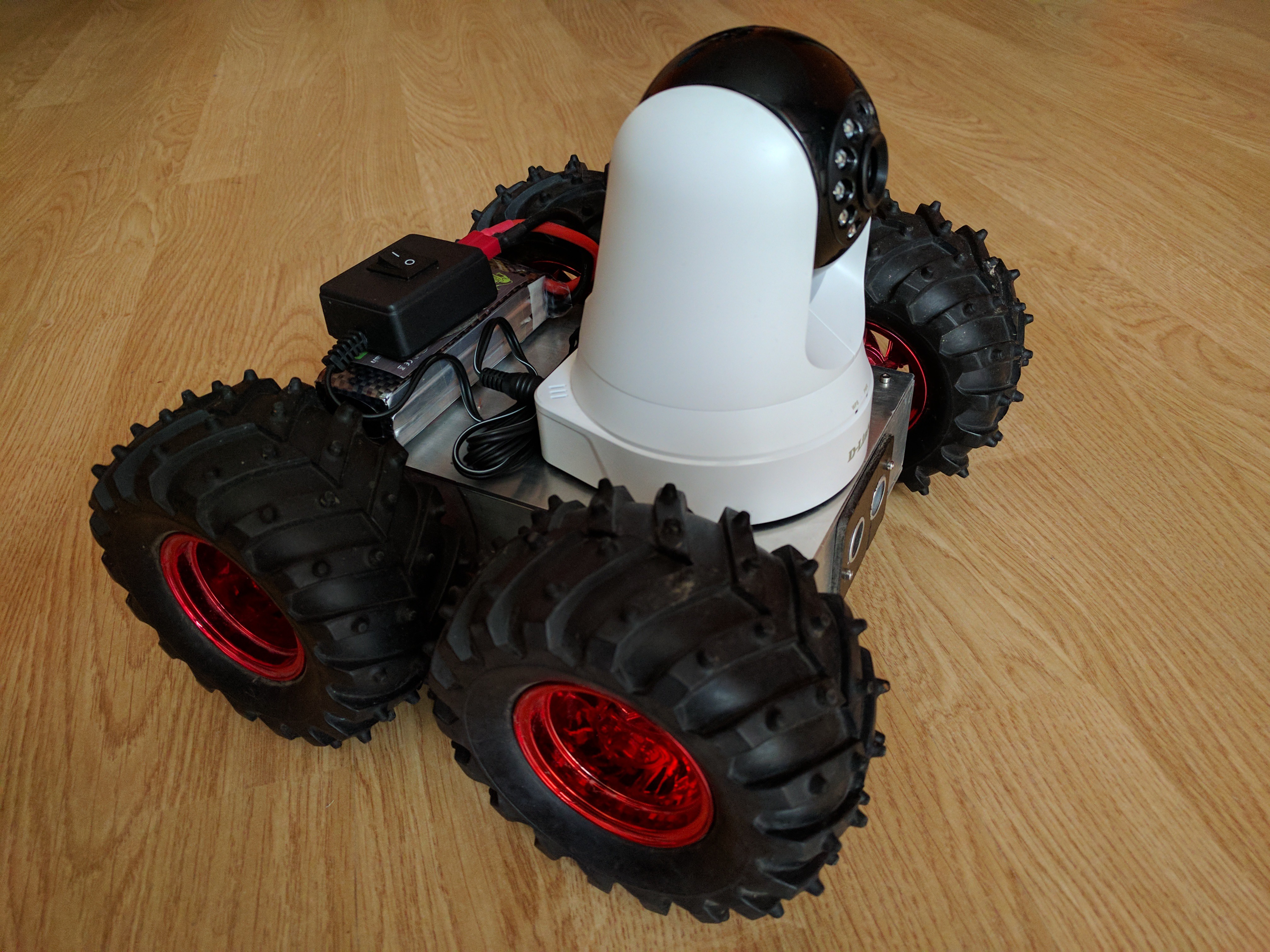
03/22/2017 at 23:23 • 0 commentsRecently I have placed a new D-Link DCS-5020L camera on my mobile robot. This PTZ WiFi IP camera is quite easy to use and suitable for testing with OpenCV.
![]()
Below is a video showing the detection and tracking of face using OpenCV.
The program has been written in Python and face detection is based on pre-trained Haar cascade classifiers from OpenCV. A simple code example of how to do this for mjpeg compression is under this link. For more information on how to track the movement of any object, see this article.
-
BME280 Atmospheric Sensor
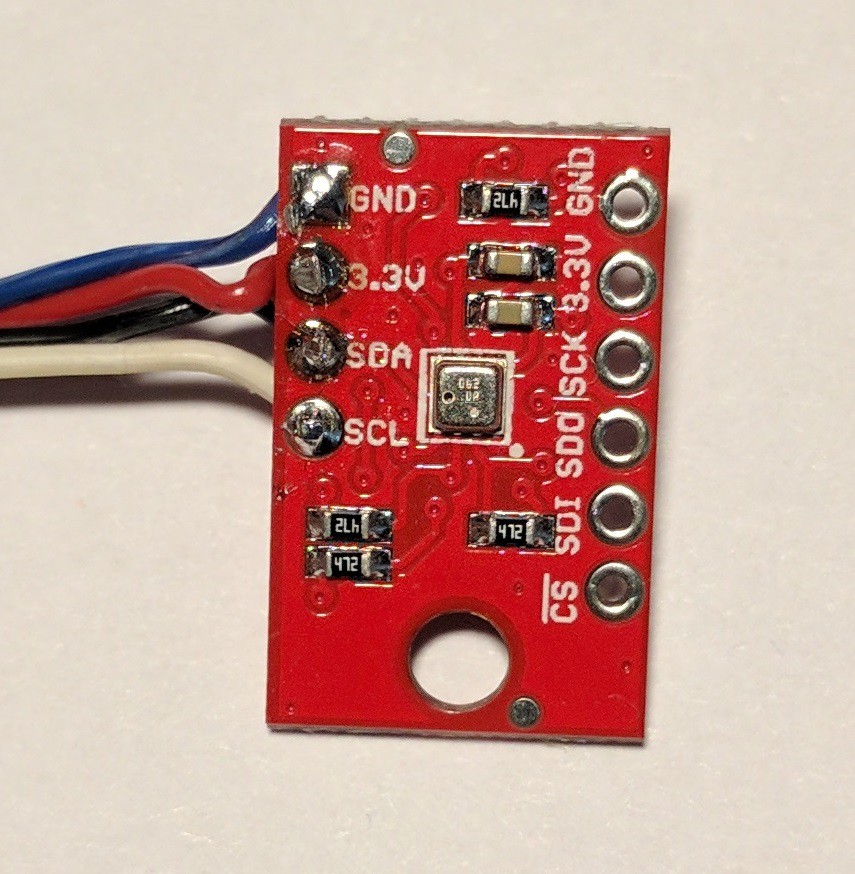
03/11/2017 at 15:14 • 0 commentsRecently when I was looking for temperature sensor for my mobile robot i found very small and inexpensive module BME280. This tiny sensor is capable of measuring up to three physical quantities: temperature, humidity, pressure/altitude. Its operating temperature range is quite wide: -40C to 85C. It is very energy efficient sensor - it takes measurements at less than 1mA and in a sleep mode less than 1µA. The easiest way to connect this sensor to the Arduino is by using The I2C bus (you do not need a voltage converter as in the case of SPI). You just need to connect four wires:
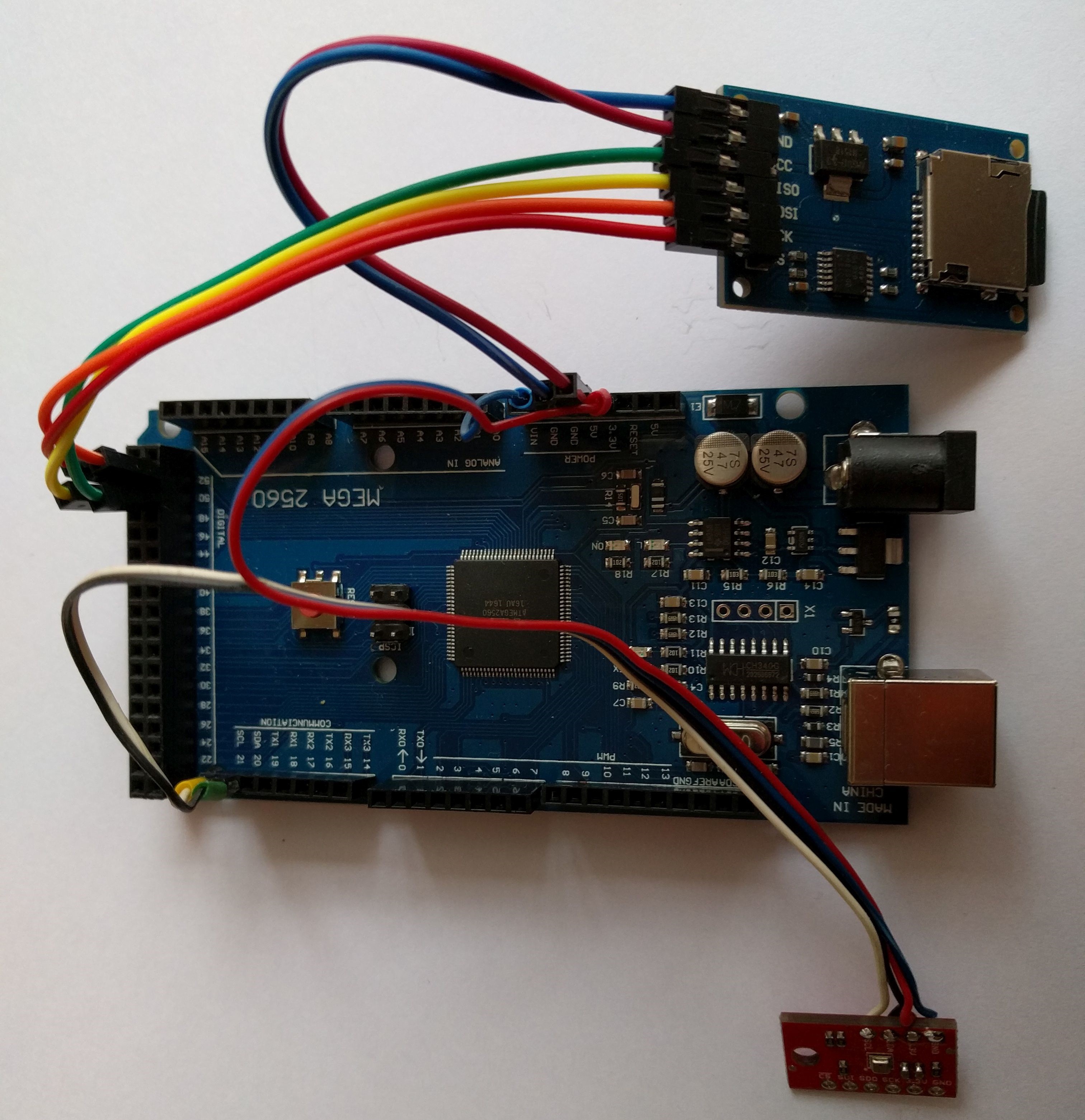
BME280 Arduino Mega 2560 GND GND 3.3V 3.3V SDA SDA (20) SCL SCL (21) ![]()
Measurement data can be stored on the micro SD card (you need to connect external micro SD card breakout to your Arduino Mega 2560). I prepared for you a simple program logging measurement data on the SD card.
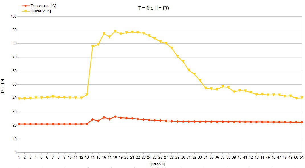
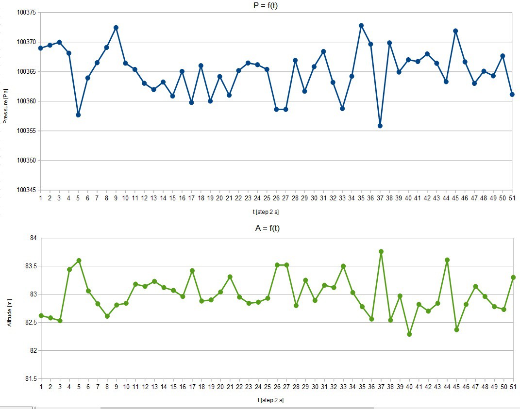
![]() Below you can see some charts of measurements taken with the BME280 sensor. The relative humidity can be measured in a range 0 - 100% RH and pressure 30 - 110 kPa.
Below you can see some charts of measurements taken with the BME280 sensor. The relative humidity can be measured in a range 0 - 100% RH and pressure 30 - 110 kPa.![]()
![]()
-
Assembling and installation of portable RPi 0 camera
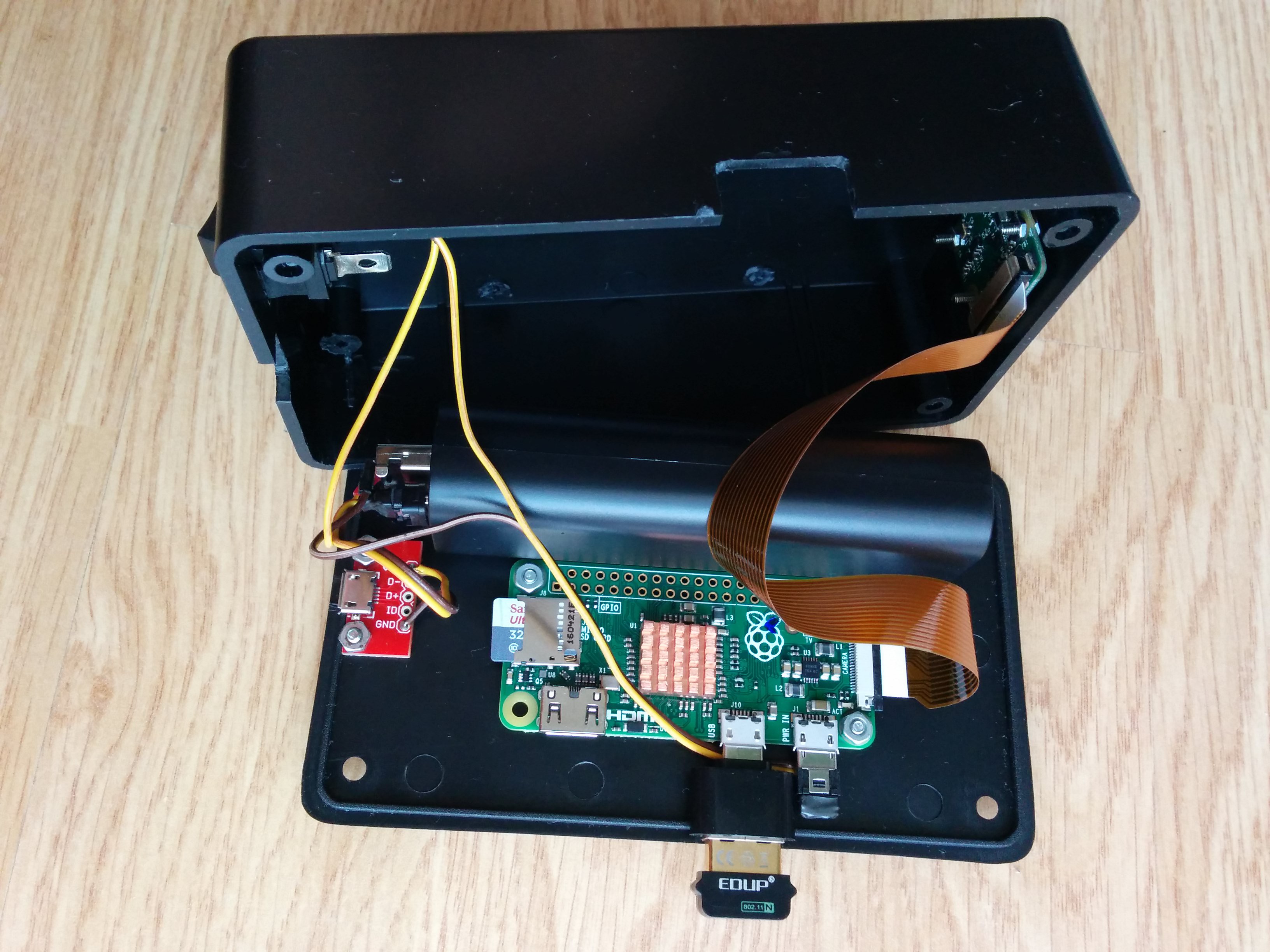
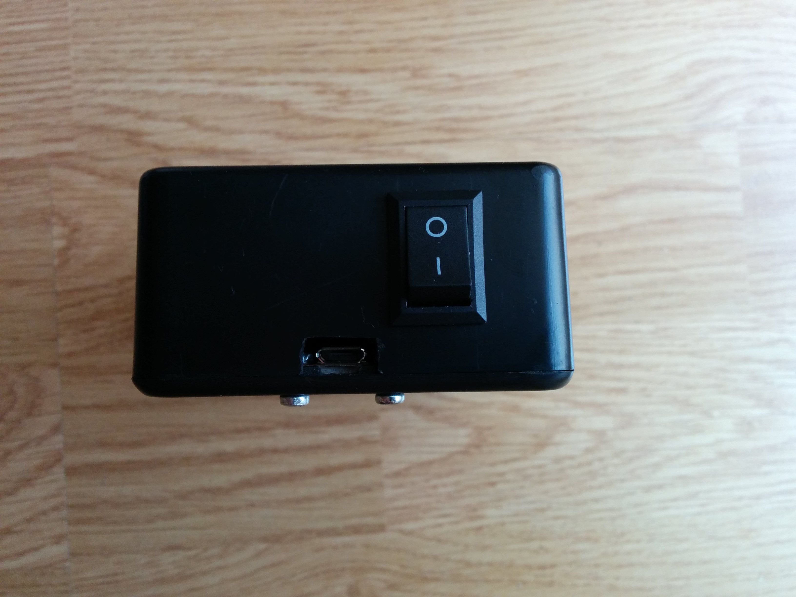
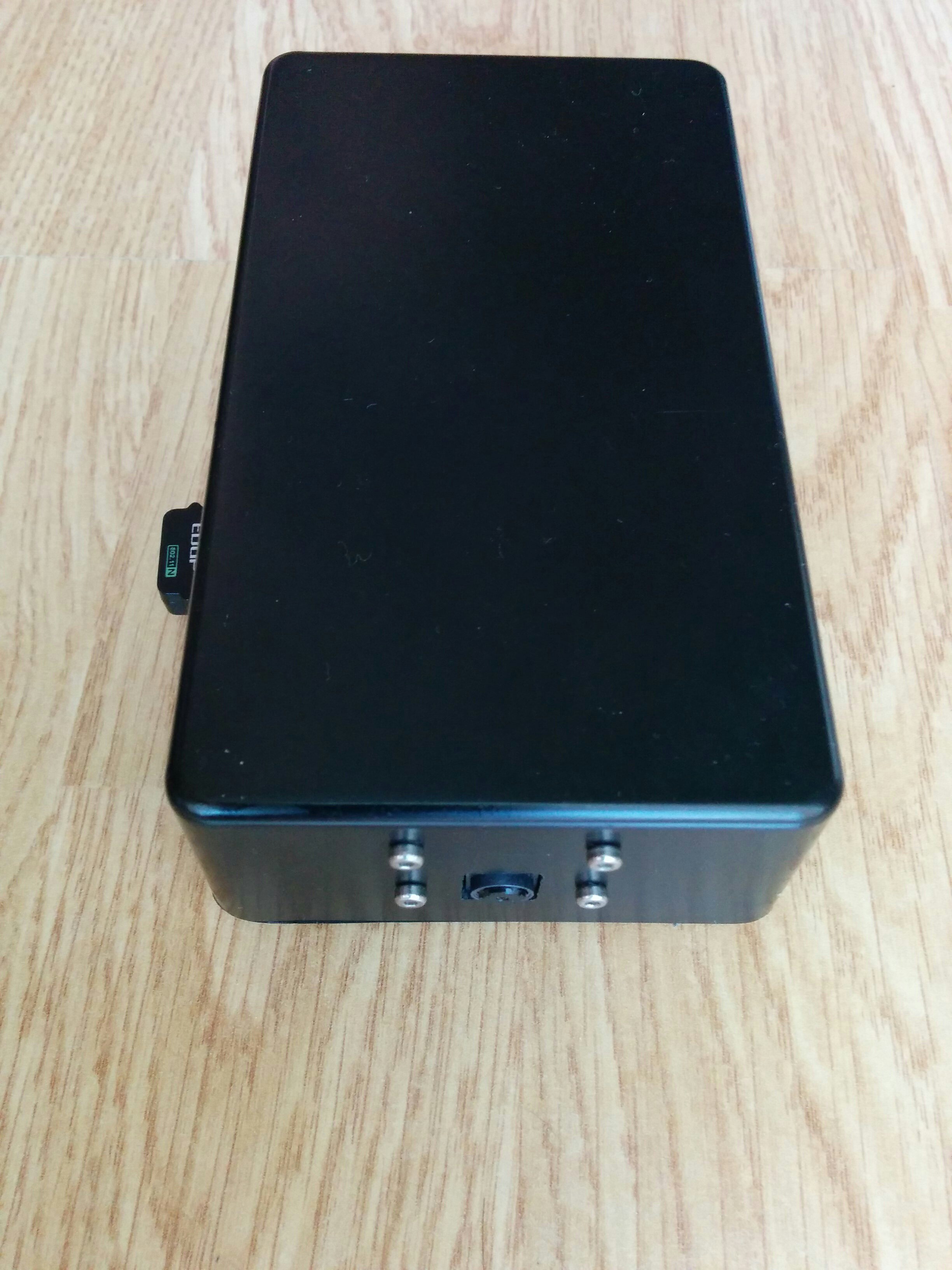
08/15/2016 at 20:15 • 0 commentsFinally I managed to buy a RPi 0. To supply RPi 0 I use a small power bank (Blow 4000mAh). Additionally I added a power switch and micro usb port for battery charging. To be able to use standard usb WiFi card you will need a small adapter (micro usb to usb). I closed all the electronics in a black plastic housing with dimensions: 124 x 71 x 38 mm. Because I wanted to be able to easily disconnecting the camera from the robot I've used strong velcro to attach the camera housing to the robot.
![]()
![]()
![]()
![]()
![]()
-
Getting started with camera
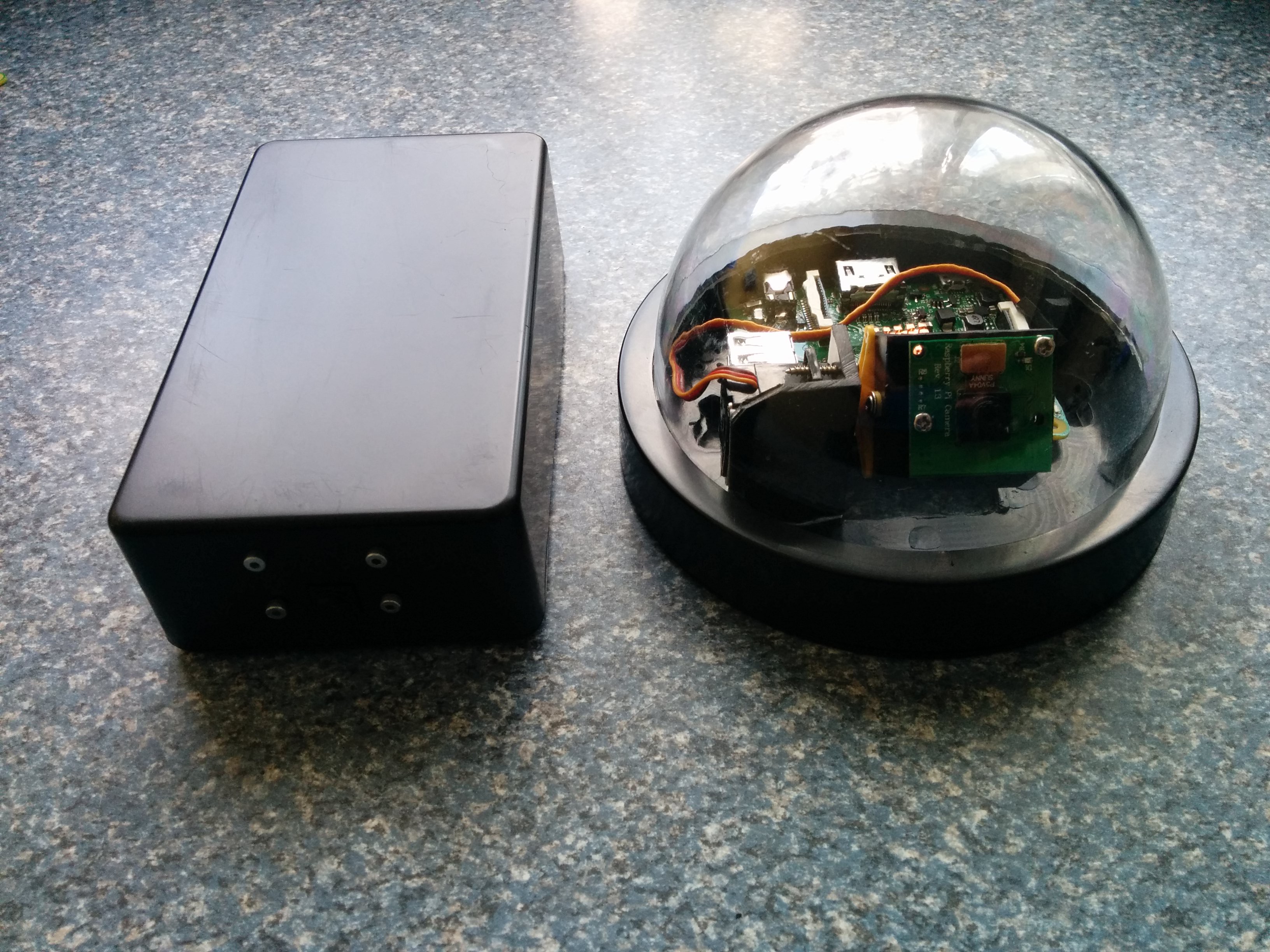
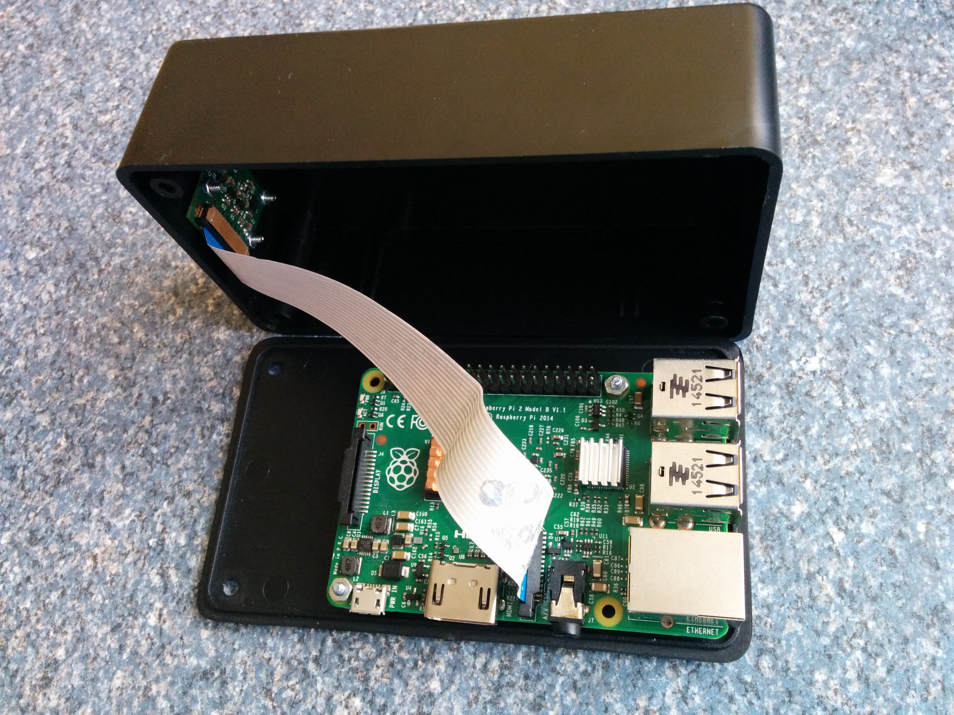
05/29/2016 at 01:06 • 0 commentsDue to the open interface and favorable price I decided to use in this project RPI camera. I considered two options for installing the camera. In the first case, the camera is stationary placed in a common housing with a RPI (black rectangular casing). In the second case the camera is vertically moveable and placed in a transparent dome. I've used the camera housing from so-called "dummy" camera for a price below 2$. This casing is, however, relatively small and only RPI zero can be easily put into it. So I'm waiting for RPI zero with camera connector and in the meantime I'm using the first option for testing.
![]()
![]()
![]()
-
Power, charging and programming
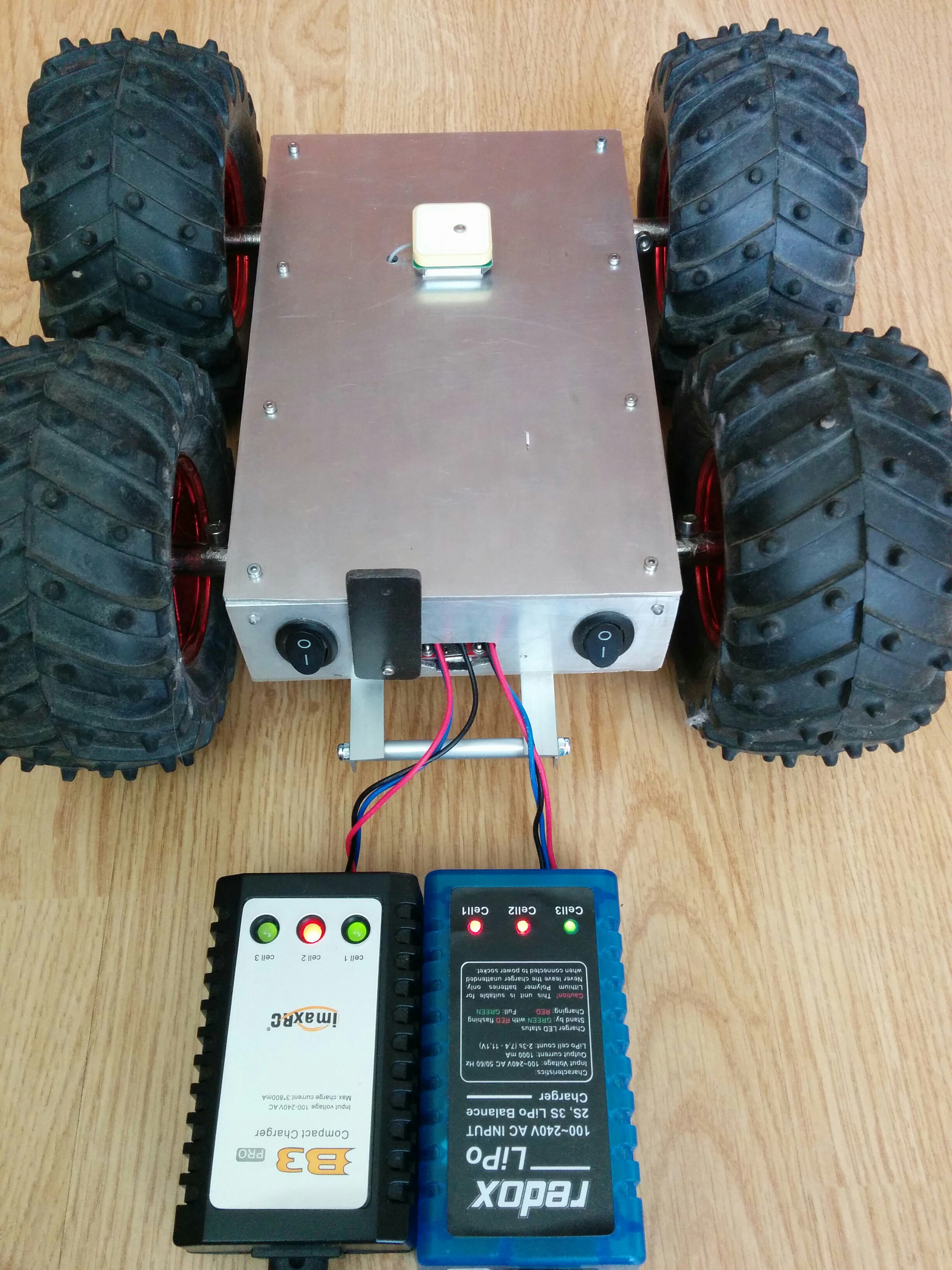
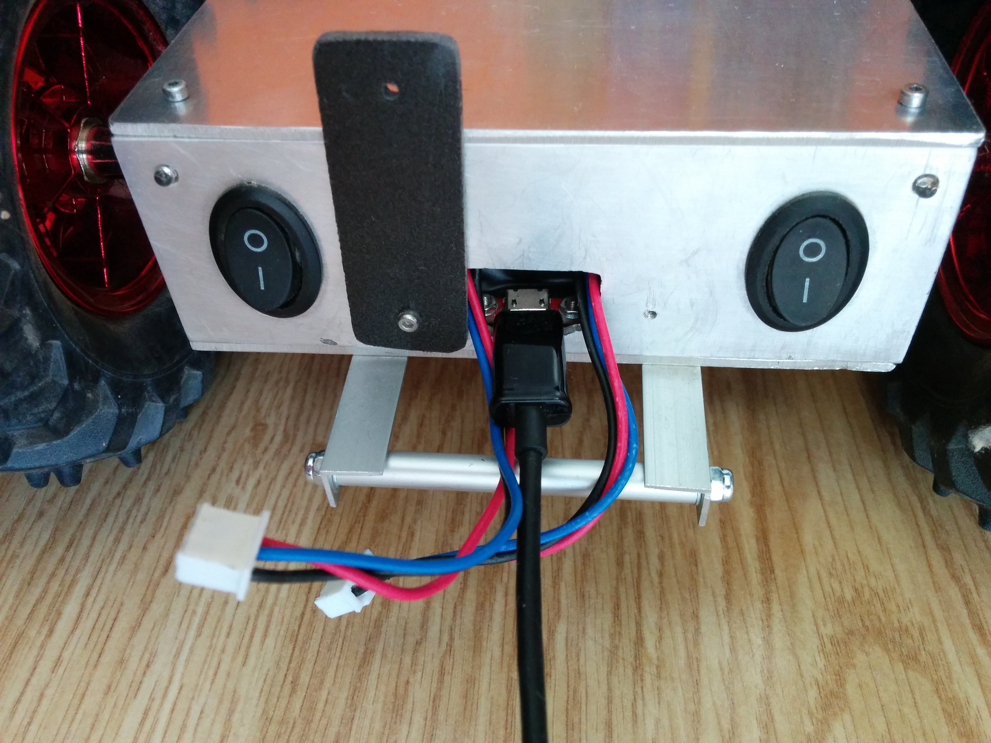
05/28/2016 at 20:53 • 0 commentsThe robot is equipped with two Li Po batteries (7.4V, 2200 mAh) . One for supplying the DC motors and the other for supplying the rest of electronic components. After opening the rear hood, we have access to two charging connectors and micro USB port for robot programming.
![]()
![]()
The DC motors are powered directly from battery with the PWM constraint such that the maximum voltage can not exceed 6V. Other electronic components are powered through the step-down voltage regulator D24V22F5 lowering the voltage from 7.4V to 5V. These regulator have built-in short-circuit protection, reverse-voltage protection, overheating protection (a thermal shutdown feature) and soft-start feature for the reduction of inrush current.
-
Overload Protection
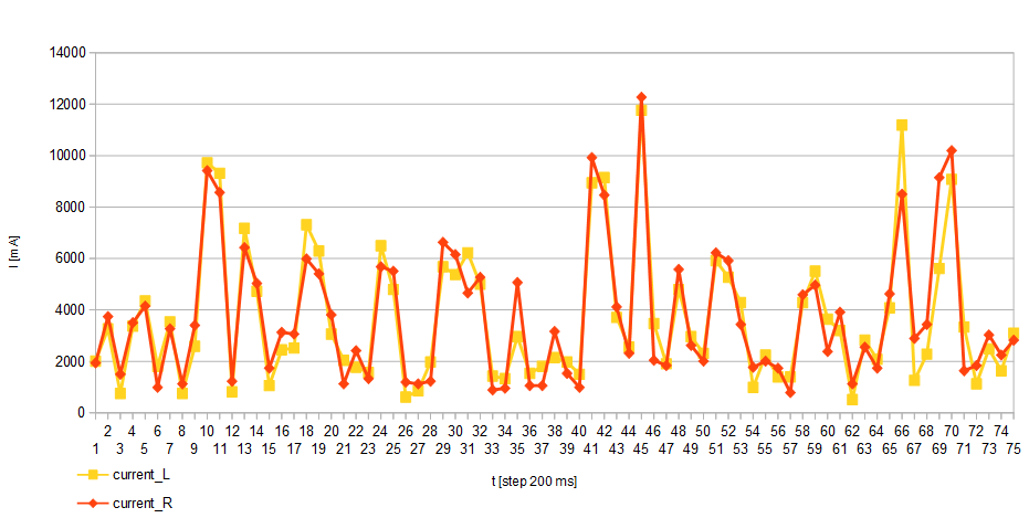
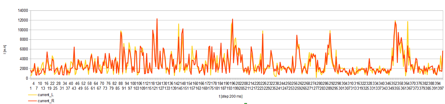
04/30/2016 at 13:41 • 0 commentsThe motor Driver Shield used in this project has current sense voltage output proportional to motor current. This feature has been used to protect DC motors against overload. In a tested case when the current per channel exceeded 9 A (4.5 A per motor) the motors power supply has been turned off. The following figures show the current consumption for the left and right channel during a test drive in rough terrain. The measurement data were recorded with a step of 200 ms.
![]()
![]()
-
GPS Tracking
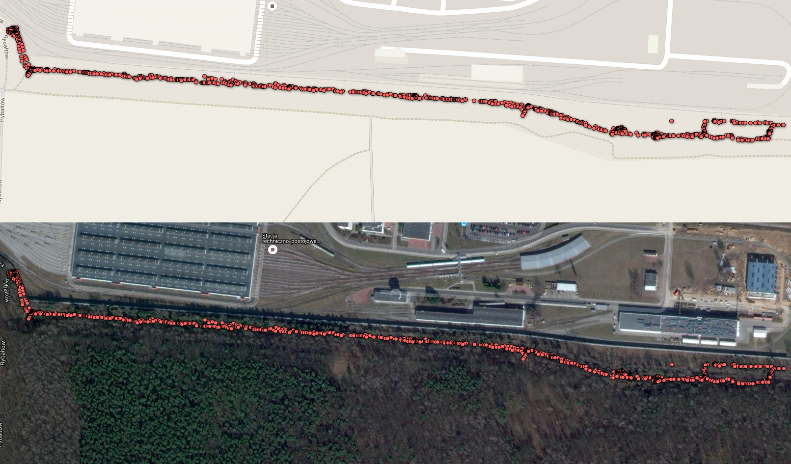
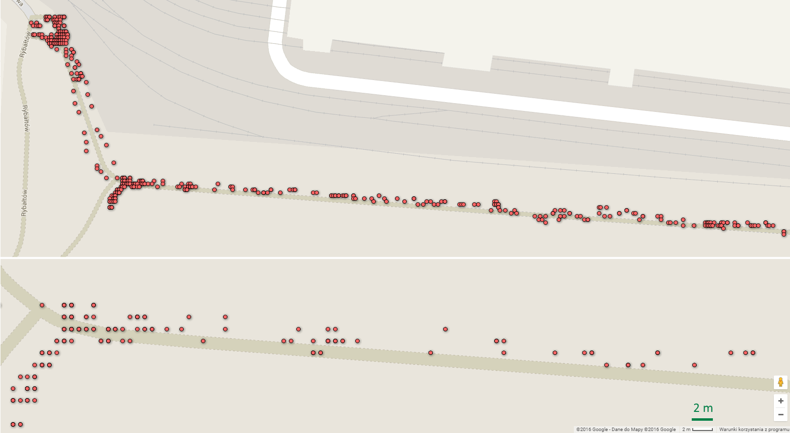
04/29/2016 at 19:02 • 0 commentsPhotos as below show the route with a length of about 1.2 km that the robot has driven in both directions. In the meantime, the robot perform various field tests. Generally, the robot moved along a path surrounded by trees.
![]()
Another photo shows an enlarged section of this path. In the lower right corner of this photo I've marked the reference distance of 2m. In these tests, I've used the NEO-6M GPS module working with horizontal position accuracy 2.5 m (CEP 50%) . This accuracy depends on weather conditions and the number of visible satellites. Soon I'm going to test and compare other GPS modules so follow the entries in this log.
![]()
-
Hardware description
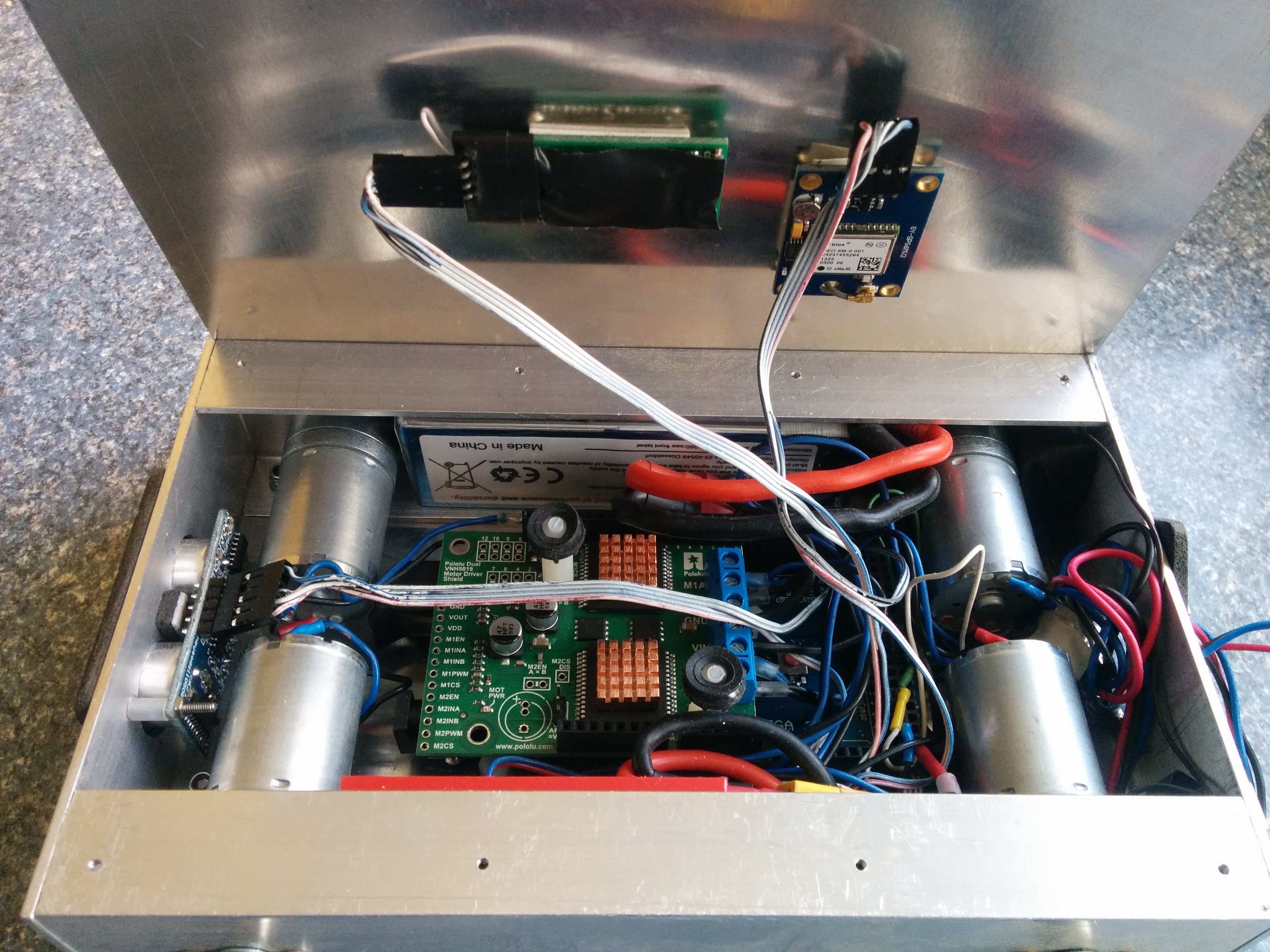
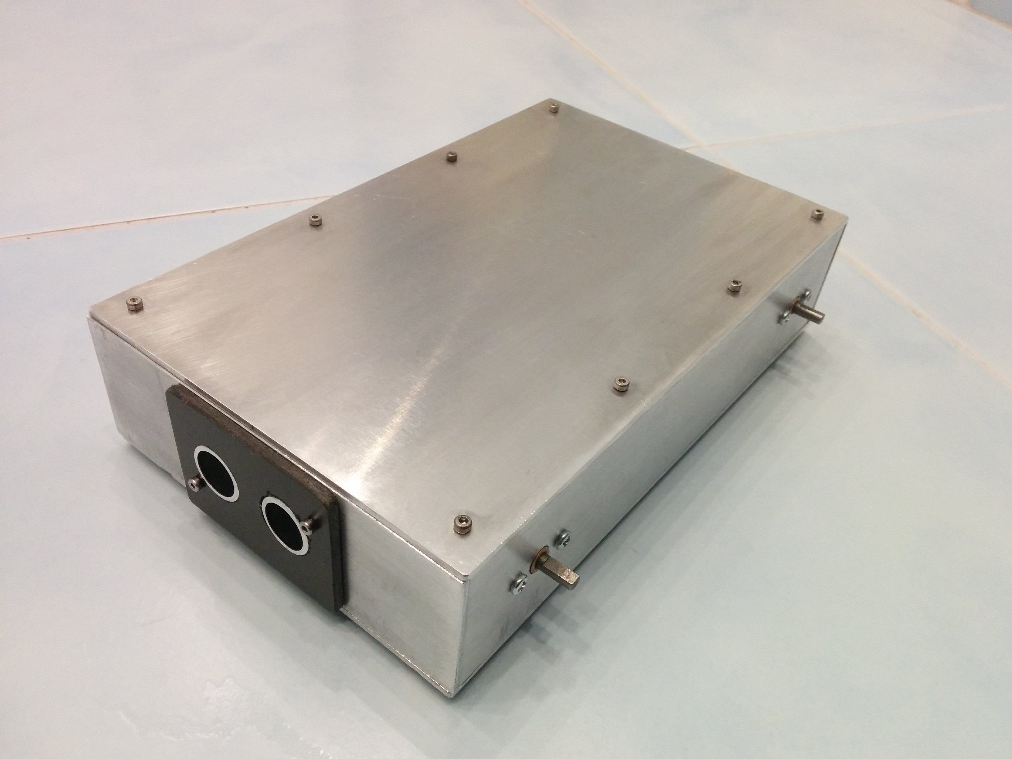
04/29/2016 at 15:13 • 0 commentsUnder the hood of the robot we can find some interesting electronics parts.
![]()
Chassis of the robot is made entirely from aluminum and duralumin. Four high-power 6 V brushed DC motors (280 RPM, 6.5 kg-cm) with metal spur gearbox (34:1) are controlled from the VNH5019 Dual Motor Driver that operate from 5.5 to 24 V and can deliver a continuous 12 A (and 30 A peak) per motor. In addition, the robot is equipped with bluetooth module BTM222, GPS NEO-6M uBlox and MinIMU-0 v2 module (Gyro L3GD20, Accelerometer and Compass LSM303DLHC).
![]()
![]()
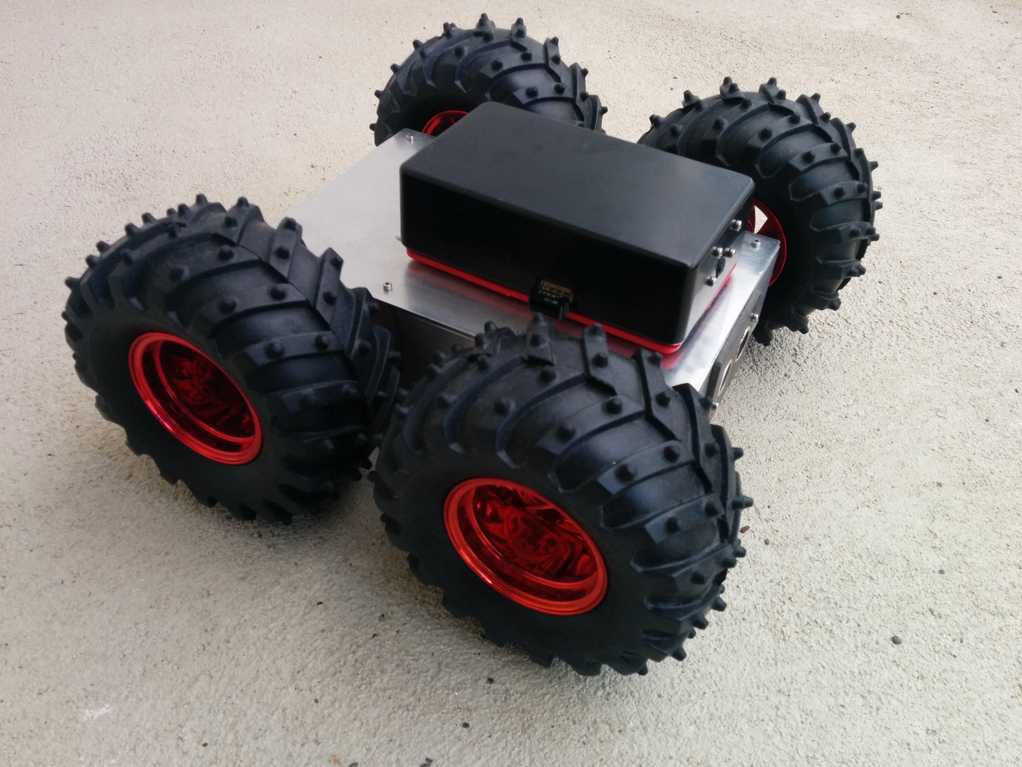
4WD all terrain robot
This is ongoing project of the mobile robot that can move in a rough terrain