Close
0%
0%

OpenExposer

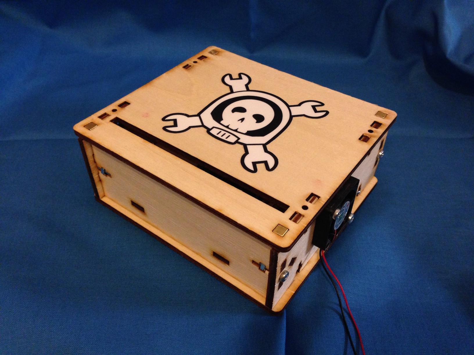
An affordable Arduino controlled multipurpose laser exposing device. Use it for SLA Printers, PCB Exposing, Laser Harp etc.

Similar projects worth following
Ever had the need for high res 3d printer, but you don't have any spare dlp projector or the money for a commercial stereolithography printer?

Have you ever tried to produce a pcb using toner transfer method and finally at the fifth try you gave up?

OpenExposer comes to the rescue. OpenExposer is a low cost and easy to use/build laser exposing unit suitable for many different applications.

Possible use cases:
- stereolithography printer
- uv pcb exposer
- laser harp
- show laser

Main features:
- unit for multiple laser exposing processes
- Arduino compatible
- low cost (standard laser printer) parts
- case parts lasercut or 3d printable
- up to 2 stepper motors can be connected
- additional I/O ports for custom extensions
- simple protocol
- extendable host software

 What is Open Exposer?

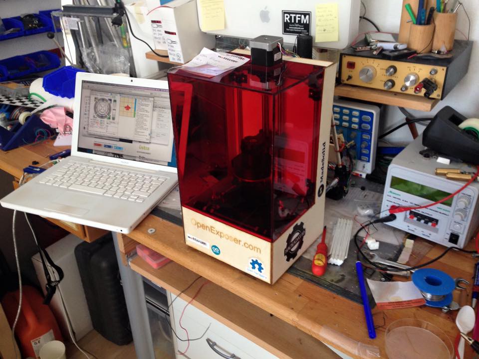
The Open Exposer is a Open Hardware device which can be used for multiple laser exposure applications. For example you can build high resolution 3d printers, pcb exposure devices and much more... 

How does it work?

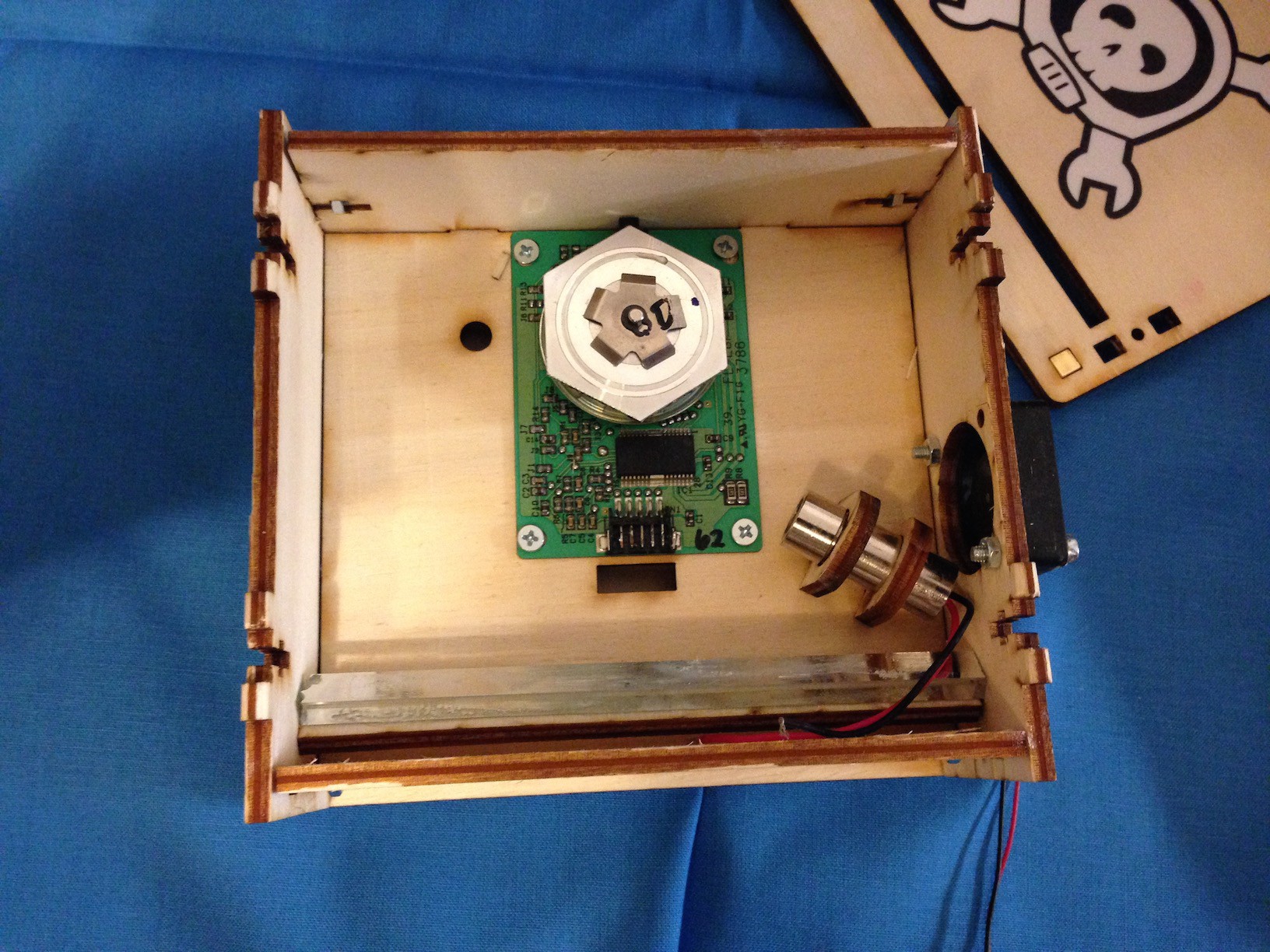
The main components of the Open Exposer are a laser and a polygon mirror. The principle is well known of laser printers. The polygon mirror is used to produce a laser line. An Arduino is used to control the device. By quickly switching the laser  on and off it is possible to generate any line pattern. The magic happens in the Arduino Firmware. You only have to set a Flag in Firmware for your polygon mirror.

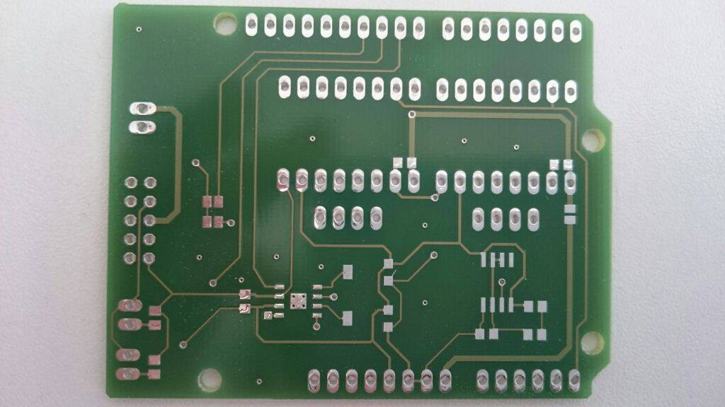
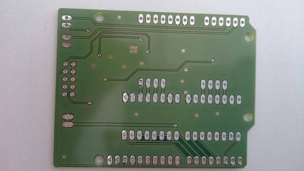
The Arduino with my self-designed Open Exposer shield is used to control the device. The Open Exposer can interpret G-Code. So it is easy to control. 

The Arduino shield will have pin outs for two stepper motors and different I/O's, which can be used for other sensors like end stops.

What can i do with Open Exposer?

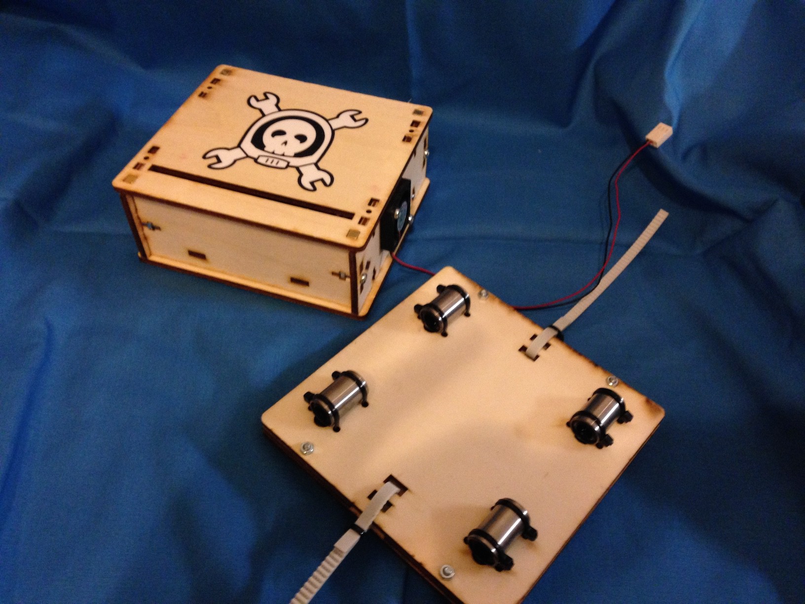
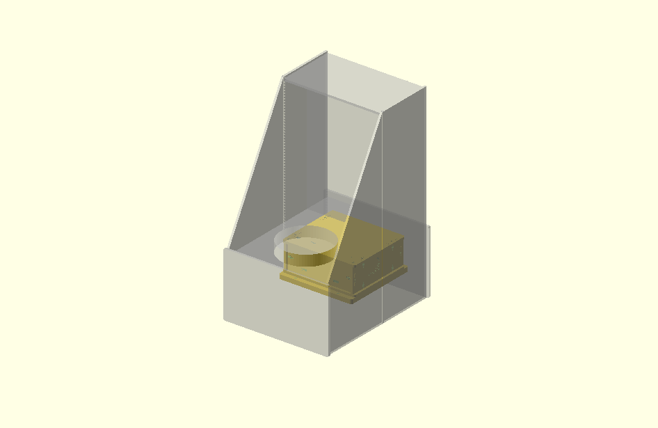
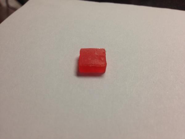
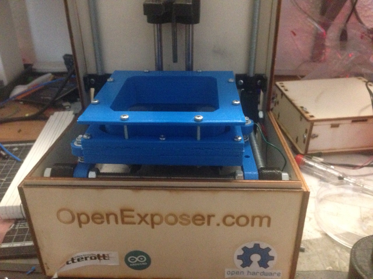
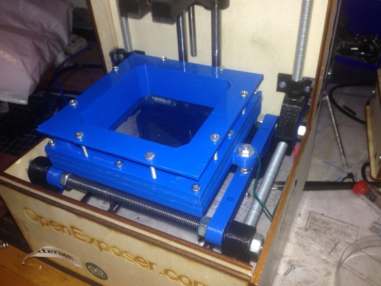
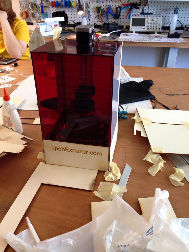
My favorite use case is a high resolution 3D resin printer, because it will be realizable for under 500 $. With the new design (laser cut parts) it will be easy to produce and easy to assemble. That is the reason why the first "prototype" extension i have built was a 3d resin printer.
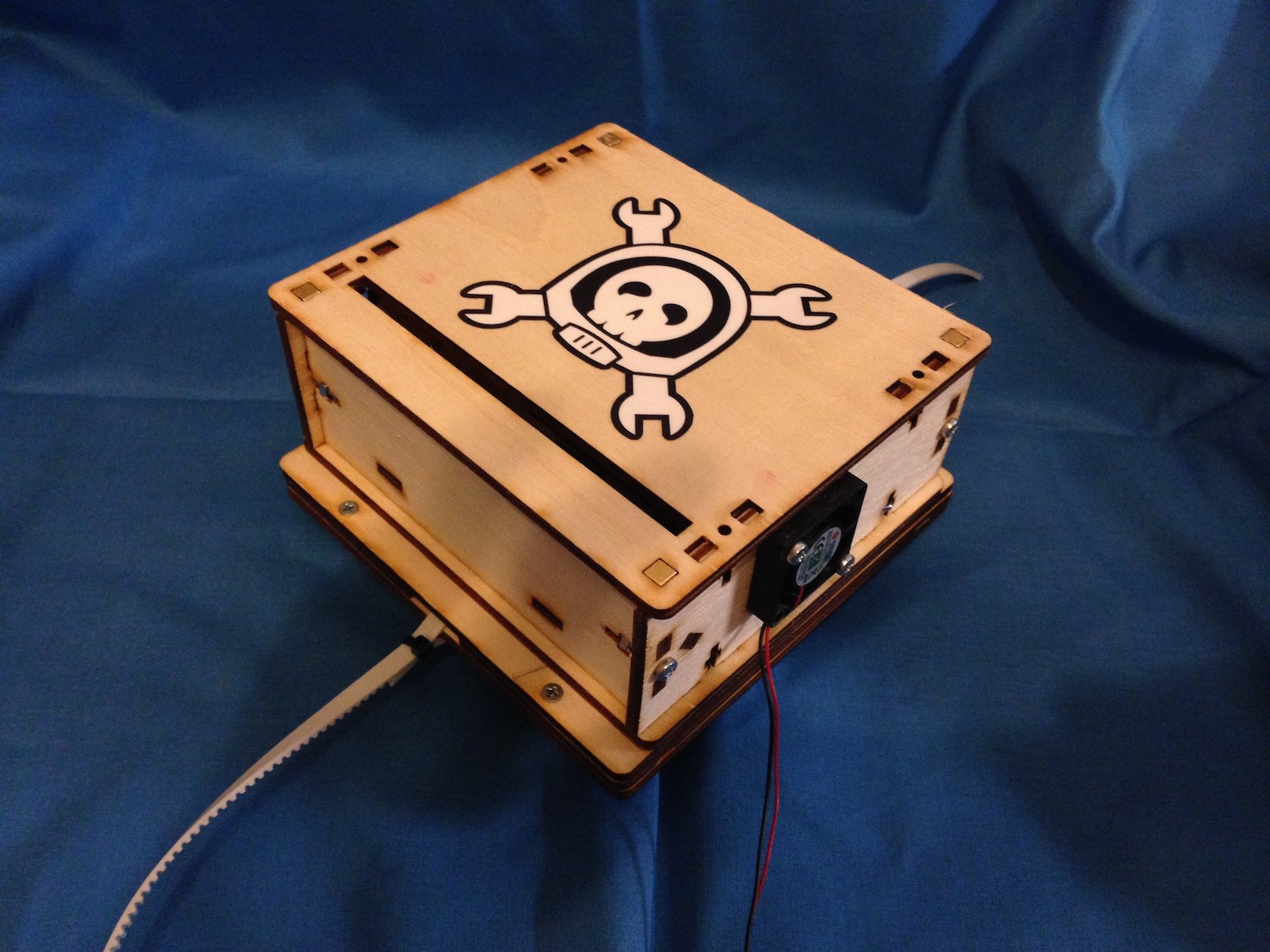
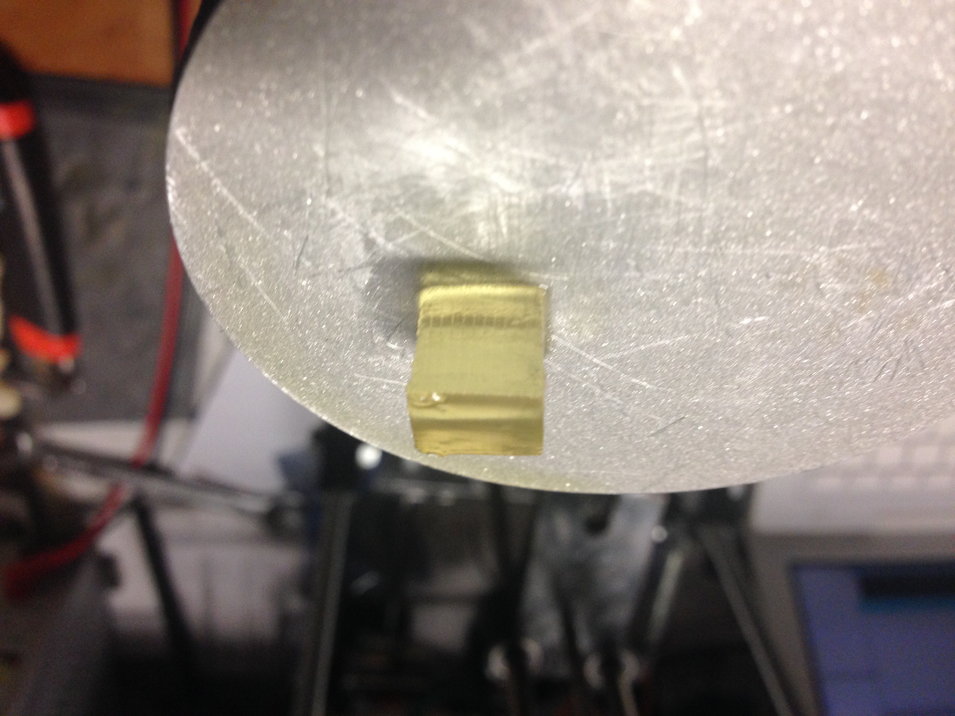
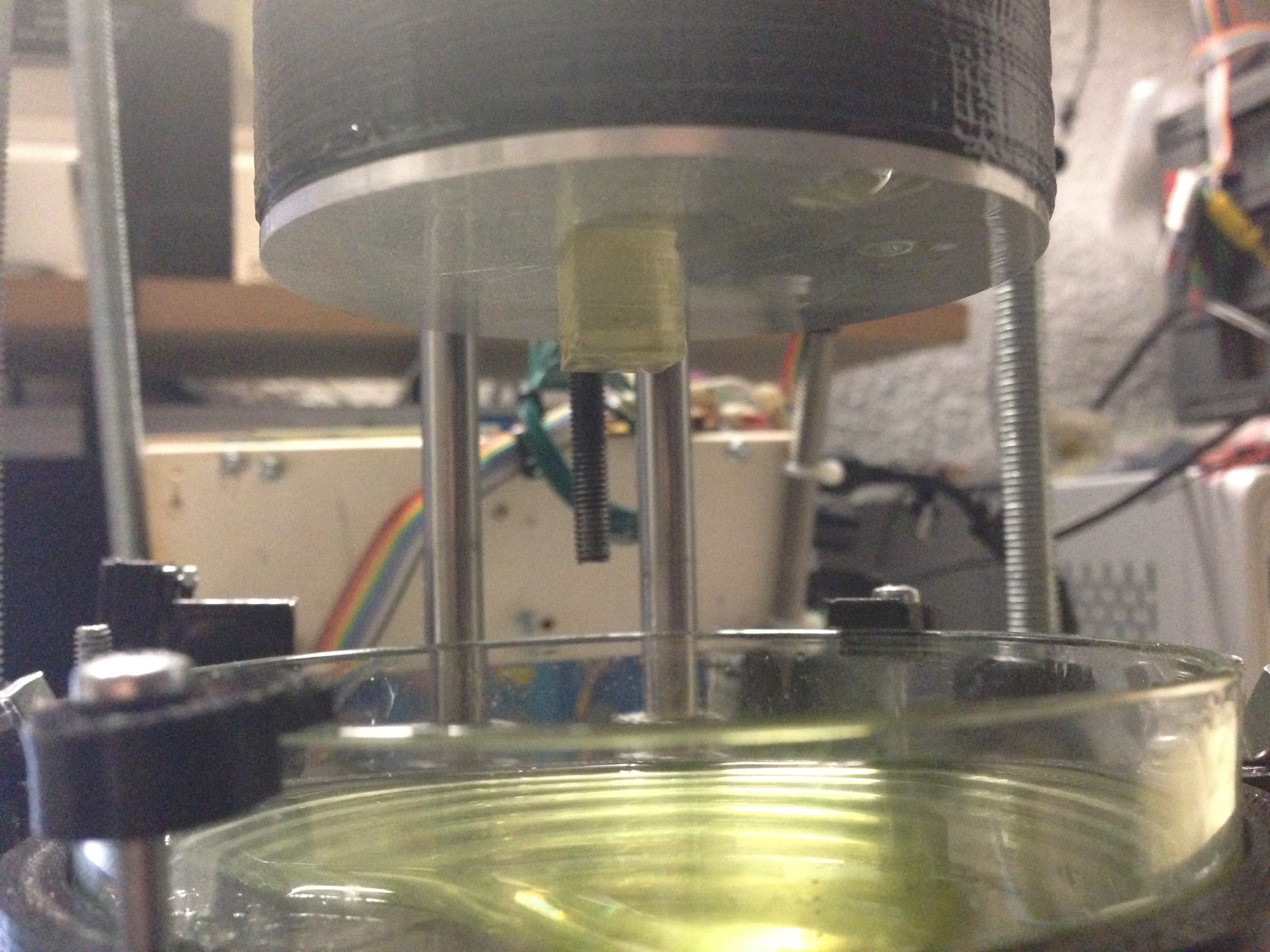
The pictures above are showing the bearing extension which is used for the 3D resin printer. 

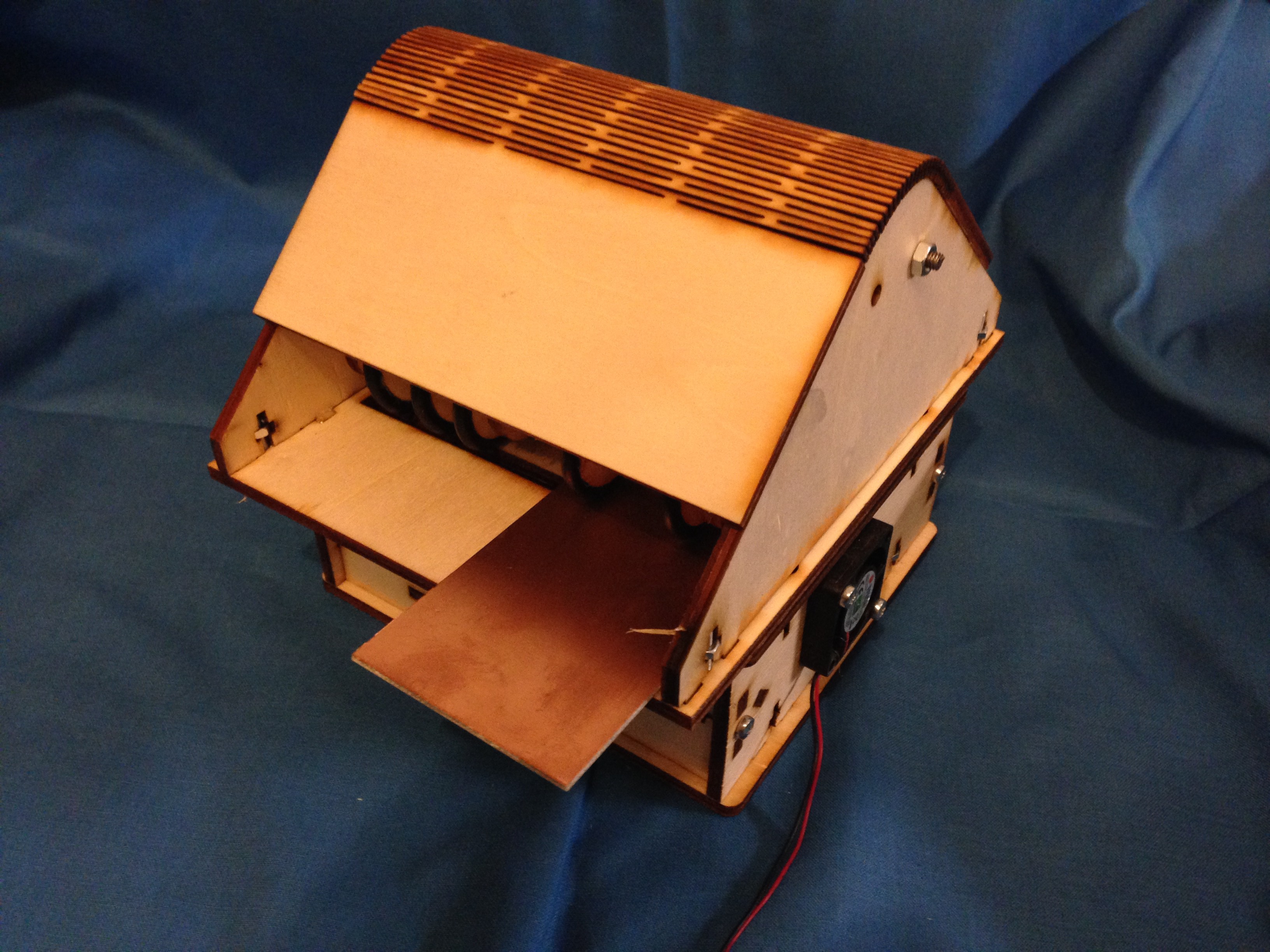
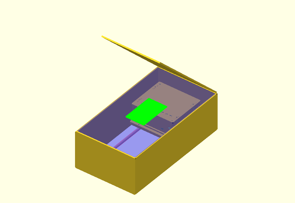
The following picture shows a possible pcb extension. It will work like a laminator. Some rolls push the photo sensitive pcb over the laser slot.

Open Exposer is an easy to build and very cheap device, because it uses standard components.

System Design

Hardware

The main unit is controlled by Arduino and the Open Exposer shield. The Open Exposer shield can carry two stepper drivers. It also contains the laser driver circuit. An additional micro controller is used for controlling the polygon mirror speed. In a later version the Arduino and the Open Exposer shield will be replaced by a single pcb. 

Software 

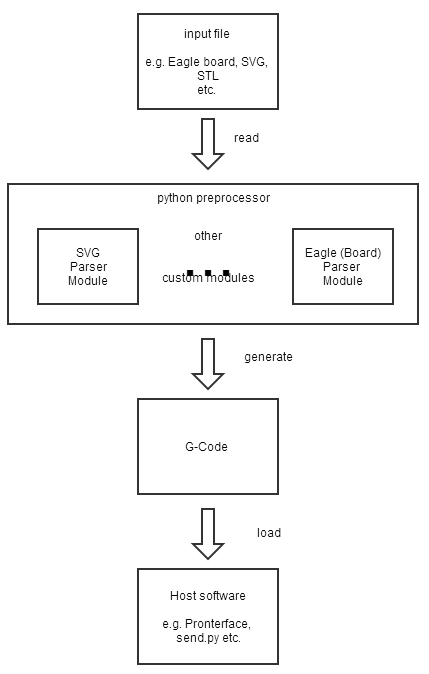
The software consists of four parts. The first part is the arduino firmware, where all the hardware controlling magic happens. 

The second software part is the third party software which is used to produce the exposing data. This can be a 3D CAD Software like OpenScad , Slic3r , Eagle and so on... 

The third software is the Open Exposer G-Code generator. The Open Exposer G-Code generator offers an interface for custom modules. It is used to generate G-Code from your third party software data. 

The fourth software part is the host software which sends the the generated G-Code to the Open Exposer.  You can find a lot of G-Code sending host software in the internet.

Some Example Videos of different prototyping stages.

Open Exposer first firmware test (exposing)

Open Exposer as 3D Printer Prototype exposing Test.


Open Exposer use case examples

High resolution resin 3D printer.

PCB exposure device. 

Used Open Components: 

Softtware: 

  • Python
  • Slic3er
  • Accel Stepper Library 
  • Printrun Tools ( as host software )
  • Hardware: 
  • Arduino
  • Laser Driver (die4drive)

  • 1 × Laser Cut or 3D Printed Open Exposer Parts case, mirror mount, laser mount etc
  • 1 × Laser Diode 405 nm uv laser diode
  • 1 × Glass Lens
  • 1 × Laser Housing
  • 1 × Laser Driver PCB

View all 14 components

View all 36 project logs

Enjoy this project?

Share

Discussions

Cleison Armando Manrique Aguirre wrote 01/06/2022 at 17:24 point

Why dont you use the laser that comes in the photocopier ? Great and astonishing project

  Are you sure? yes | no

rajhlinux wrote 01/02/2021 at 12:41 point

what kind of lens is used here?

  Are you sure? yes | no

frank wrote 10/04/2017 at 04:18 point

This is a great looking concept. I'm looking for a 3D printer that will give similar resolution to a  small build area DLP design (~40um XY, ~40um layer) with a build area of about 30mm X 200mm. Using a poly mirror to scan a laser over the short dimension and moving the scan line across the long dimension with steppers seems ideal. I don't really care about speed as long as its "reasonable". UV compatible optics scare me ($$$) and maybe I don't need all them with this, but it seems like a mirror wobble correcting lens would still be important to optimize resolution.  Also, mirror faces may need to be highly polished (more $$$).  I realize its been several years since anything seems to have happened on this project, but I would appreciate feedback on this application if possible.

  Are you sure? yes | no

Hexastorm wrote 05/11/2017 at 10:00 point

Mario great project; but you should use a transparent instead of a reflective polygon. In addition, you should add a beaglebone.

  Are you sure? yes | no

George I Fomitchev wrote 08/12/2016 at 12:14 point

really exciting idea ...

you can also unleash it with 2.1W and 3.5W diode lasers (EnduranceRobots.com)

  Are you sure? yes | no

jeek123 wrote 08/09/2016 at 13:47 point

hi,Mario,it's a good project.

i see the polygon mirror have five pins. i also read your firmware. 

#define LASER_PIN         9

#define LASER_PORT        B
#define LASER_BIT         1
#define LASER_PWM_PORT    D
#define LASER_PWM_BIT     6
#define LASER_PWM_PIN     6

i have a question,how the pins of  polygon mirror mapping the arduino pins?

  Are you sure? yes | no

shahzeb wrote 06/15/2015 at 12:33 point

Hi,

How are you able to sync the mirror and laser such that the scanlines start at the start of each face?

  Are you sure? yes | no

Films4You wrote 06/06/2015 at 14:30 point

Looks like it could make a good 3d printer scanner to scan objets for files to be 

3d printed

  Are you sure? yes | no

Jasmine Brackett wrote 08/15/2014 at 22:23 point
Hello Mario, I just wanted to remind you that this is the checklist of what must be on Hackaday Projects by August 20th for OpenExposer to be considered for the next round of The Hackaday Prize:
- A video less than 2 minutes long describing your project. Put it on YouTube (or Youku), and add a link to it on your project page.
- At least 4 Project Logs (you've got 14, so that's covered)
- A system design document. Please highlight it in the project details so we can find it easily.
- Links to code repositories, and remember to mention any licenses or permissions needed for your project. For example, if you are using software libraries you need to document that information in the project details.
Thanks for entering and good luck!

  Are you sure? yes | no

mbasecnc wrote 07/09/2014 at 08:12 point
Hi Mario, very interresting project.
How long does it take to print the resin examples you made, will a stronger (+200mw) uv laser improve the curing speed. I'm planning to create a printer similar to yours and are wondering wat the laser power does to the curing time.
Thanks for your help.

  Are you sure? yes | no

Mario Lukas wrote 07/09/2014 at 09:41 point
At the moment i am playing around with different exposing times. This small example took 5 mins. Maybe it is faster with a stronger laser. But it also depends on the used resin. When the whole process is stable i will work on efficiency.

  Are you sure? yes | no

k wrote 06/26/2014 at 13:33 point
what is the thing you are holding the resin in made of? I have read that you need something that is non stick and UV transparent.

  Are you sure? yes | no

Mario Lukas wrote 07/02/2014 at 09:46 point
Sorry for my late reply, but i am preparing my Maker Faire booth. For this early version i am using Perti dishes. The dishes are coated with ELASTOSIL RT601 ( it is like Sylgard 184). In germany it is hard to find a shop which sells Sylgard 184. So i decided to give ELASTOSIL RT601 a try. It works, but it is expensive. When the printing process is stable i will do some research to find a cheaper material.

  Are you sure? yes | no

Jasmine Brackett wrote 06/10/2014 at 19:01 point
Hello Mario, if you want to enter this project for The Hackaday Prize, login and use the 'submit to' under your project images on the left hand side. Any problems give me a shout.

  Are you sure? yes | no

Mario Lukas wrote 06/10/2014 at 19:26 point

Thanks, done.

  Are you sure? yes | no

Mario Lukas wrote 06/09/2014 at 17:04 point
@dandumit, @nmz787 Sorry i was at a Rock Festival during the last 5 days. I will post some more details during the next days.

  Are you sure? yes | no

dandumit wrote 06/07/2014 at 06:04 point
Very nice project ! I would like to use it to expose my PCB boards. Would you please give some more details regarding speed of mirror ? On logs you said that you are using an attiny 2313 to lower the speed. I have also some exposing units and I would like to try this.

  Are you sure? yes | no

Mario Lukas wrote 06/10/2014 at 08:09 point
Thank you. I will design the PCB Exposing Unit after the Makerfaire Hannover. The attiny2313 is used to regulate the mirror speed which currently is 55 rotations per second at 333 Hz scanrate.

  Are you sure? yes | no

nmz787 wrote 06/05/2014 at 02:30 point
I've been very interested in using a blu-ray writer optical sled, taking advantage of all the engineering money that went into the optics and beam shaping... I know the DOF is quite shallow, but I want to do micro-SLA (exposing photoresist with micron or sub-micron sized beam spots).... What do you think about that? Others have used a laser pointed into the ocular (eye piece) of a microscope, then tracing the laser by adjusting the microscope stage... but my thoughts are the beam shape degrades, and requires a microscope... with blu-ray optic and laser, you just would need another old CD/DVD rom to complete a 2 axis CNC laser.

Best regards!

  Are you sure? yes | no

Mario Lukas wrote 06/10/2014 at 08:19 point
The microscope solution should be possible, have a look at the following link: http://goo.gl/29oGWL
There was a talk at our Dorkbot meeting a few month ago. As i remember they used telescope or microscope optics.

  Are you sure? yes | no

frank wrote 05/29/2014 at 20:22 point
Nice. I've just started a similar project. I'm using a closed looped galvonometer as used in light shows to deflect the laser. It is placed about 1 meter away from the vat, and uses a lense that focus to a point at 1 meter. That way I get minimal distortion as the beam moves from left to right.

  Are you sure? yes | no

x3n0x wrote 05/14/2014 at 19:39 point
Just curious, have you approached the problem of varying focal length as you trace the arc from the polygon mirror? Laser printers use a specialized type of lens to insure the focus is consistent, allowing a consistent spot size over the entire sweep of the beam. Those funny curved lenses you see in the scanner housings you got the poly mirrors out of are what do the trick. The math is not trivial... You have to solve a complicated differential equation to generate a lens solution. This really becomes an issue if you want to use the device for PCB direct exposure without a mask. If you use a mask though, the laser simply becomes a light source, and the process proceeds like a normal photo etch process.

  Are you sure? yes | no

Mario Lukas wrote 05/19/2014 at 15:13 point
Thank you for your suggestion. Yes i know the problem of varying focal length. But the lens which you can find in laser printers is made for a infra red wave length. I think they absorb to much of the uv laser power, so they are not suitable. I am trying different approaches to solve it. It actually also works great without a lens. It's all a matter of resolution. But in the first step i have to get the process stable.

  Are you sure? yes | no

x3n0x wrote 05/19/2014 at 22:42 point
You are correct about the lenses! They are also plastic, so any substantial laser power will result in damage to the lens. The ones I looked at were not treated or coated in any way because of cost, and depending on the material might work OK for UV if the laser power is weak enough. I asked because I was looking at building a similar system, and was looking at some other solutions for scanning the laser that do not involve changing the focal length over the scan area. I was curious what you had done. Good luck with everything!

  Are you sure? yes | no

Mario Lukas wrote 05/21/2014 at 20:26 point
The main focus of the OpenExposer Project is on the little red box which should contain all electronic and optical parts. This box should be clampable to different modules. The 3D printer which i am building currently is only one of those clampable modules. For PCB etching i am planing to design a module which works like a laminator. The whole project is "work in progress". You can find some people who already did it with and without those lenses behind this link http://www.mikrocontroller.net/topic/306825#3645579 (in german only)

  Are you sure? yes | no

RodolpheH wrote 05/14/2014 at 08:46 point
For stereolithography, this kind of system isn't optimal but you can try to get it better than any others. However, you should know there is some patents on 3D printing using a laser projection system. I hope you won't get caught ;)

  Are you sure? yes | no

Mario Lukas wrote 05/19/2014 at 14:58 point
Thank you. I use this kind of system because it is a very cheap solution. And everybody with an old laser printer laying around is able to build it. Most of the patents ran out in the last years.

  Are you sure? yes | no

Eric Evenchick wrote 05/12/2014 at 11:01 point
What kind of laser does this use? I haven't worked with photolithography, but do you need specific laser power or wavelength to expose the resin?

  Are you sure? yes | no

Mario Lukas wrote 05/12/2014 at 11:24 point
At the moment i use a 405 nm laser diode with 80mw and it works great with the resin from Spot-A-Materials (spain). I will post some more pics soon. For PCB exposing you will need more power, for that usage i recommend a laser diode with up to 1w.

  Are you sure? yes | no

Eric Evenchick wrote 05/12/2014 at 13:48 point
Are those hard to get due to regulations on importing lasers (at least in the US)?

  Are you sure? yes | no

Mario Lukas wrote 05/12/2014 at 13:58 point
I bought mine on ebay. Laser diode and lens module (housing) separated. The driver board is also custom made. So i had no problem to get the parts (in germany).

  Are you sure? yes | no

Mario Lukas wrote 05/12/2014 at 14:02 point
By the way, laser protection glasses, or laser safety glasses, are an absolutely necessary part of the safety apparel!

  Are you sure? yes | no

Similar Projects

Does this project spark your interest?

Become a member to follow this project and never miss any updates