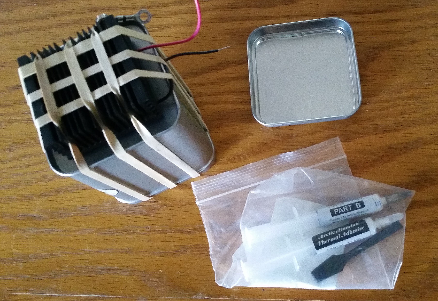
Desktop Cooler is a peltier device strapped to an endothermic source to assist in the lowering of the surrounding ambient temperature. This will allow for the cooling of air and or beverages. Reversing the polarity going to the peltier device will result in warming the air and or beverage, given that the device is no longer physically connected to a block of ice.
Here, the idea is to have a container with ice, use the peltier device transfer energy from the warm surrounding air into the ice and turn it into water. Once the water (or the ambient temp) has reached a "certain" temperature the device will stop. This will require temperature sensors for ambient temperature, a temperature sensor for the water/ice container and possibly a temperature sensor for the fan. Reading these sensors will be a micro controller which will also be responding to conditions and user input.
Files
Preliminary_Test_Code_05-24-2016.ino
Don't get too excited, I just grabbed some stuff from the examples and shoved it into a single UGLY sketch. Again this is a copy from my other project, they are currently running in parallel tracks. there will come a time when the software will most assuredly branch because the projects have a very different theme. But this is test software after all for testing the new hardware (experiment PCB). So please deal with it until the branch or put something in the comment section.
I grabbed my bench supply some ice and water and hooked the Peltier device up again. This time I took more thermal images (still downloading the Fluke app) As promised this device pulls 5 amp @ 12 volts (~60 watts). As the temperature differential gets smaller the current draw seems to decrease (at least this preliminary test shows that) maybe there is a possibility to run open loop and just follow current for control?
So after 30 minutes the ice water is hot (~40*C) but the heatsink still remains fairly cold-ish to the touch, I still think this idea might work, less liquid more solid H2O will be necessary depending on the set temp expected.
I removed the multi-directional clamping apparatus and filled the cold chamber with solid and liquid HOH. I connected the 10A input of a DMM to the "Black" wire of the Peltier device and connected the "Red" wire of the device to the positive terminal of a 9 volt battery (not the best power source but the most convienient at the time).
The Peltier device moved 2.5 amps of current while the battery had it available to supply. I will need to review the Peltier device current requirements and limitations (and consequences of exceeding those limits).
The heat-sink temp dropped substantially (I took some thermal images but none before filling the chamber) when the Peltier device was "engaged."
The battery temp doubled while the Peltier device was connected.
I did not monitor the voltage of the battery (I was more concerned with the supply current).
I did not monitor the temperature (more than take a few thermal images) of the "fluid" in the chamber or the heat-sink during operation of the device.
I will need to connect a real bench top supply and retest with some more instrumentation at a later time.
I will also have to load the silly fluke software to upload the thermal images that I captured.
I used the thermal adhesive and mounted the heat-sink to the Peltier device to the cold chamber. Next I can mount a fan using "conventional" methods and with the prototype PCB I should be able to test the crazy notion is using stored endothermic energy to cool air like discharging a capacitor.
Last night I sat down and wrote a bit of code to test the experiment PCBs. I have a servo, a DC motor, (ran by PWM from an analog input) to adjust the duty) and the LED connected to pin13 working. I did notice that I forgot my soft pull down resistor on the digital input switch that I added. OOps. Blue wire to the rescue, should be easy enough, there is a ground trace close to the switch that I can tie a 1k0 smd if I scratch the coating off the trace and drop some slobber.
I ordered some artic alumina to mount my Peltier device to the "cold chamber" on one side and the heat-sink on the other. I am hoping that this will be enough to hold the three things together without needing any other method of fixation. I was a bit worried about this because I really didn't want to poke holes into the chamber and risk leak points.
The PCBs (to test the not yet written software using the Teensy3.2) have arrived and they test OK (except the one that I soldered the LM317 in backward!). I used an L293 Dual H-bridge driver for the fan and peltier device control. This way I can make the device shuttle electrons either way to warm or cool the heat-sink . The same goes for the fan, though I am not certain it will be necessary to drive the fan in both directions. The fan might end up being controlled by something else and I may use the second channel to drive a peristaltic pump, but again I don't know that I will need to drive that in different directions.
Great job on our HackADay World Create Day!