-
11Step 11
Connecting the dongle to the Arduino Board requires removing the plastic covering from the dongle and soldering wires to 4 of the pins
-
12Step 12
Remove the plastic covering from the USB dongle
-
13Step 13
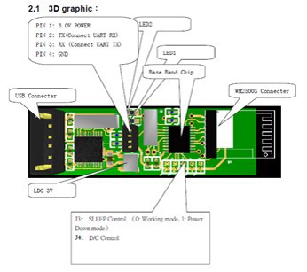
Once the cover is off, the RF dongle board will be as shown in the picture below
![]()
-
14Step 14
Find the 4 pins, located in the center of the board.
-
15Step 15
Starting at the end with the ‘ + ‘ sign the pin assignments are:
–Pin 1 (starting at +): 3.0 V Power–Pin 2 : TX–Pin 3 : RX–Pin 4 : Ground -
16Step 16
Connect a 4 pin connector into these pins
-
17Step 17
Connect wires to these 4 pins, leaving enough wire to connect to the Arduino
-
18Step 18
Use a Knife to destroy the connections from these PINs to the Chip inside the RF dongle.This is to ensure that the brain wave signals received from the Mindwave is sent to the Arduino and no the internal chip in the RF dongle
-
19Step 19
The Mindwave RF dongle uses a 3.3 V power.Connect the +ve of the RF dongle to Arduino’s 3.3 V Output pin
-
20Step 20
Connect the dongle’s Tx directly to the Arduino’s Rx(Pin 0).Connect the dongle’s Rx to the Arduino’s Tx (pin 1).You can add a voltage divider to reduce the voltage going to the dongle’s Rx pin because Arduino sends 5V whereas Dongle uses only 3.3 V.It is not absolutely necessary to add a voltage divider but it is good to avoid any harm caused using the excess voltage
Mind Controlled Robot
Mind Controlled Robot - A device to make paralyzed people control their movements using brain waves.

Discussions
Become a Hackaday.io Member
Create an account to leave a comment. Already have an account? Log In.