Close
0%
0%

LCIRIC - Low Cost Infrared Imaging Camera

A standalone, open-source thermal imager which can be built for under $50 in parts.

Similar projects worth following
Thermal cameras are useful in a number of applications ranging from circuit design to home maintenance. I have used several FLIR imagers at work and have found them to be valuable troubleshooting tools. However, even the least expensive commercially available thermal cameras start at $200 and go up from there. This is hard to justify for a tool you may only use occasionally. New small thermal sensors, in particular, the Panasonic GridEYE series, should make it possible to build a basic thermal imaging camera for under $50.
I am aware of several similar projects on hackaday.io. However, in my view, this project will improve on those by:
- Offering standalone operation operation with a reasonably sized color touch screen.
- Targeting a much lower-cost BOM with multiple build options.
- Providing a simple user interface and a durable enclosure.

Overview

This project will attempt to build a functional thermal imaging camera for under $50, $150 less than the least expensive commercially available thermal imagers currently on the market. Although it uses only an 8x8 pixel sensor, this device should be a significant improvement over the single point non-contact type thermometers which might otherwise be used by a home or hobbyist user.

I am aware of at least two similar projects currently on hackaday.io. In particular:

https://hackaday.io/project/1974-tj-99-thermal-imager

https://hackaday.io/project/1389-grid-eye-ble-capable-thermal-camera

I believe this project will improve on those in the following ways:

  • Standalone operation. Phone-based devices have their place, but in my opinion, standalone devices are almost always more convenient, more durable, and don't become obsolete nearly as quickly. In addition, they leave your phone and its ports available for other functions.
  • Unique features. I would like to add the ability to save thermal images to an SD card. I also plan to add data logging features to record thermal imaging data periodically, or stream it over serial and USB for integration into your own test setup. If I have time, I would also like to add optional WiFi for remote viewing and data transfer, and I would also like to add support for a color camera module which would support capture and possibly thermal overlay as well.
  • Lower cost. By careful component selection and system design, I believe I can get the parts cost to about half of what previous projects have suggested.
  • User Experience. My hope is to provide a user-friendly user interface and a custom 3D-printed enclosure to make the final device approachable for non-technically-minded users.

Proposed features

CPU: LPC11U67 ARM Cortex M0+ running at 48MHz

Thermal imaging sensor: Panasonic GridEye 3.3V Low Gain

Visible imaging sensor (optional): Omnivision OV2640 module; onboard JPEG compression; image data buffered by AL422B

Interface: 2.4" Color Touch Screen (ILI9341 LCD controller; XPT2046 Touch Controller); Side Buttons

WiFi interface (Optional): ESP8266

Power: 1x 1.5V AA Alkaline/Ni-Mh OR 1x 3.7V 14500 Lithium-Ion (with USB charging)

Supports saving thermal and visible light images to SD card. Supports streaming image data and camera commands over USB-CDC interface or TTL serial. Supports accessing SD card using USB-MSC protocol. Supports time-lapse data logging to SD card.

Cost Breakdown


PartApproximate CostNotes
GridEYE sensor$22
LCD w/ Touch screen; SD Slot$6.50Aliexpress
Microcontroller (LPC11U67)$3
Battery Management$2.50
Power Supply (AMS1337)$2
Misc. Passive Components$6
Printed Circuit Board$2.50dirtypcbs.com
Total$44.50


Build Options

One of the goals for this project is to provide several different hardware build options. In particular, the OV2640 image sensor will add at least $10 to the BOM cost, and the addition of WiFi via ESP8266 will add several dollars to the BOM cost as well. These components can be left off the board when assembling it without causing problems if minimum cost is desired. Buttons may be mountable on the left or right sides of the device to accommodate left- or right-handed users. If onboard lithium battery charging is not desired, those components may be left off as well.

Software

The sofware will be developed in C using NXP's LPCXpresso development environment. All software will be released on BitBucket. The software will be released under the MIT license. The display driver is based loosely on Adafruit's ILI9341 driver (https://github.com/adafruit/Adafruit_ILI9341), which is released under the MIT license.

  • USB Serial Interface

    Josh Lange05/28/2016 at 01:22 0 comments

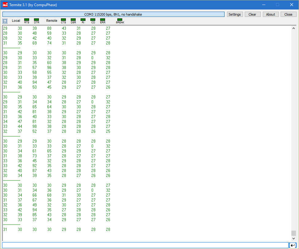
    I've implemented a basic virtual serial interface that runs over the USB port. The current implementation just prints all the temperature values in a grid format whenever there is a new reading available. Each reading is separated by a row of dashes. The temperature values are rounded down to the nearest degree. The sensor does report temperature with 0.25 degree resolution, but I am currently doing everything using integers only.

    It would be pretty straightforward to write a small program to capture and display this data if, for example, you wanted to log something over a period of time. I'm planning to write a python script which demonstrates this eventually.

    Here's a screenshot of the output when pointing the device at the same two resistors used in the last post. The two dead pixels are visible in the second row, last two columns, with the values of (0 32).

  • Infrared Sensor Working!

    Josh Lange05/27/2016 at 21:31 0 comments

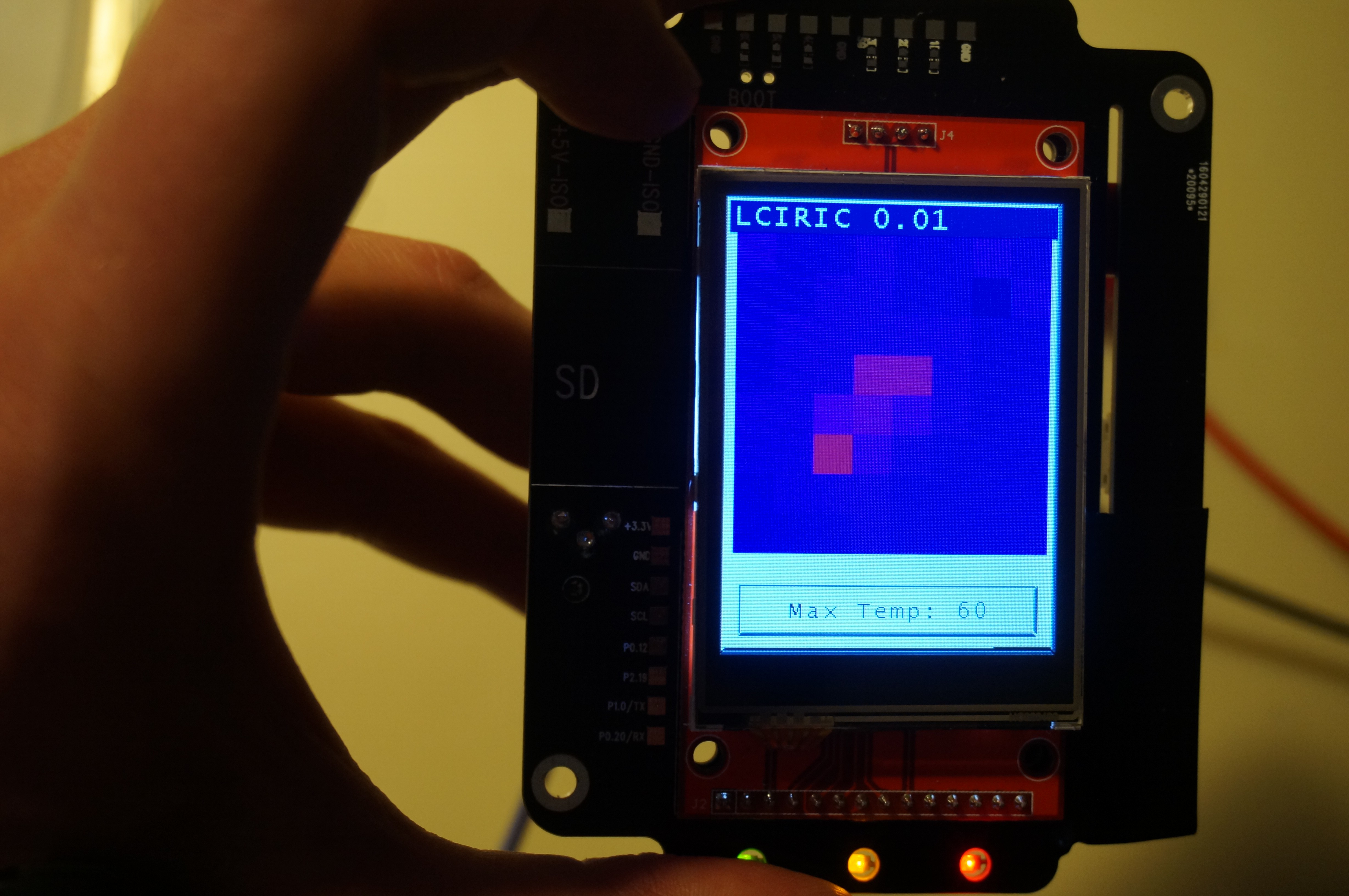
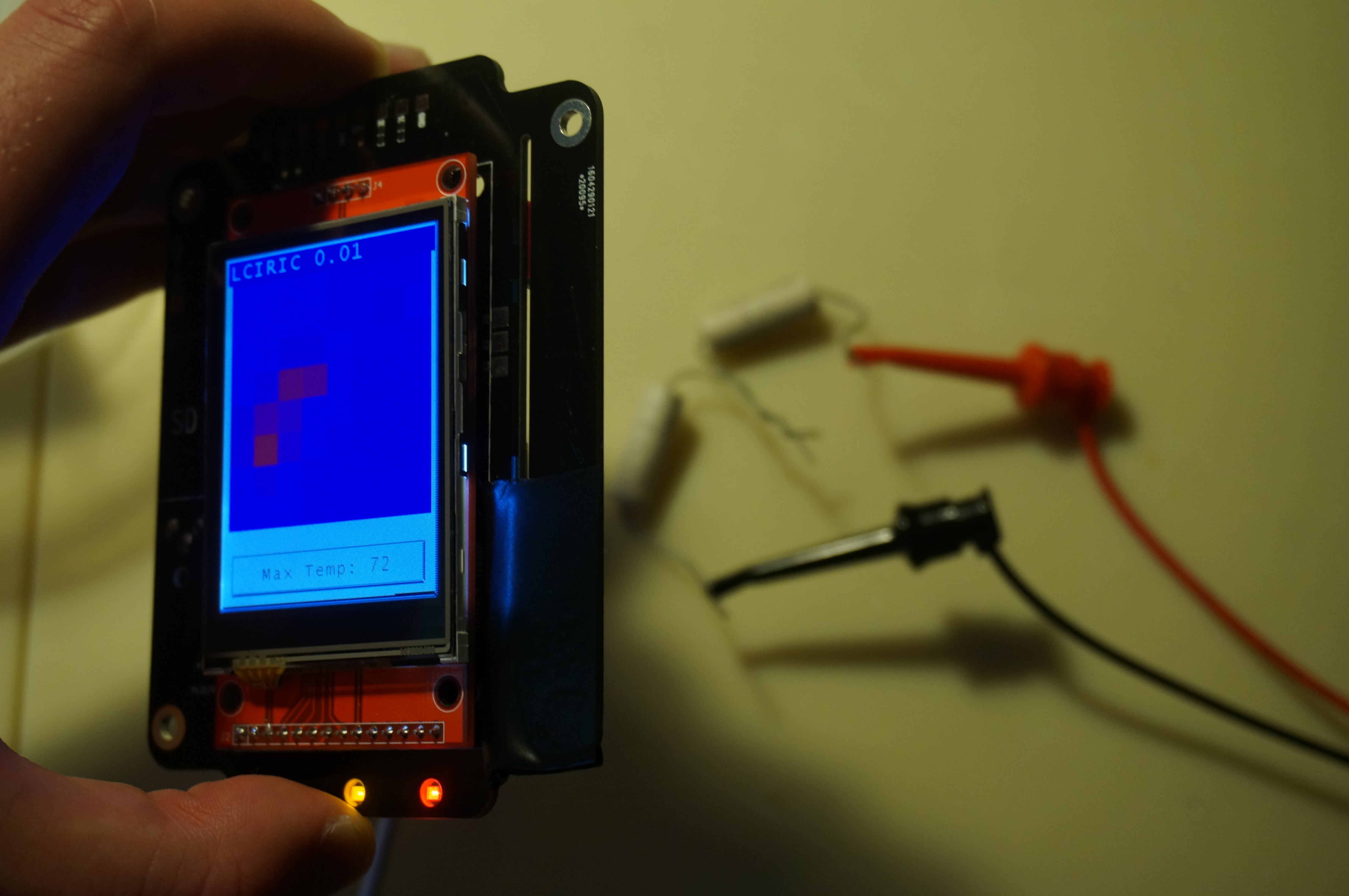
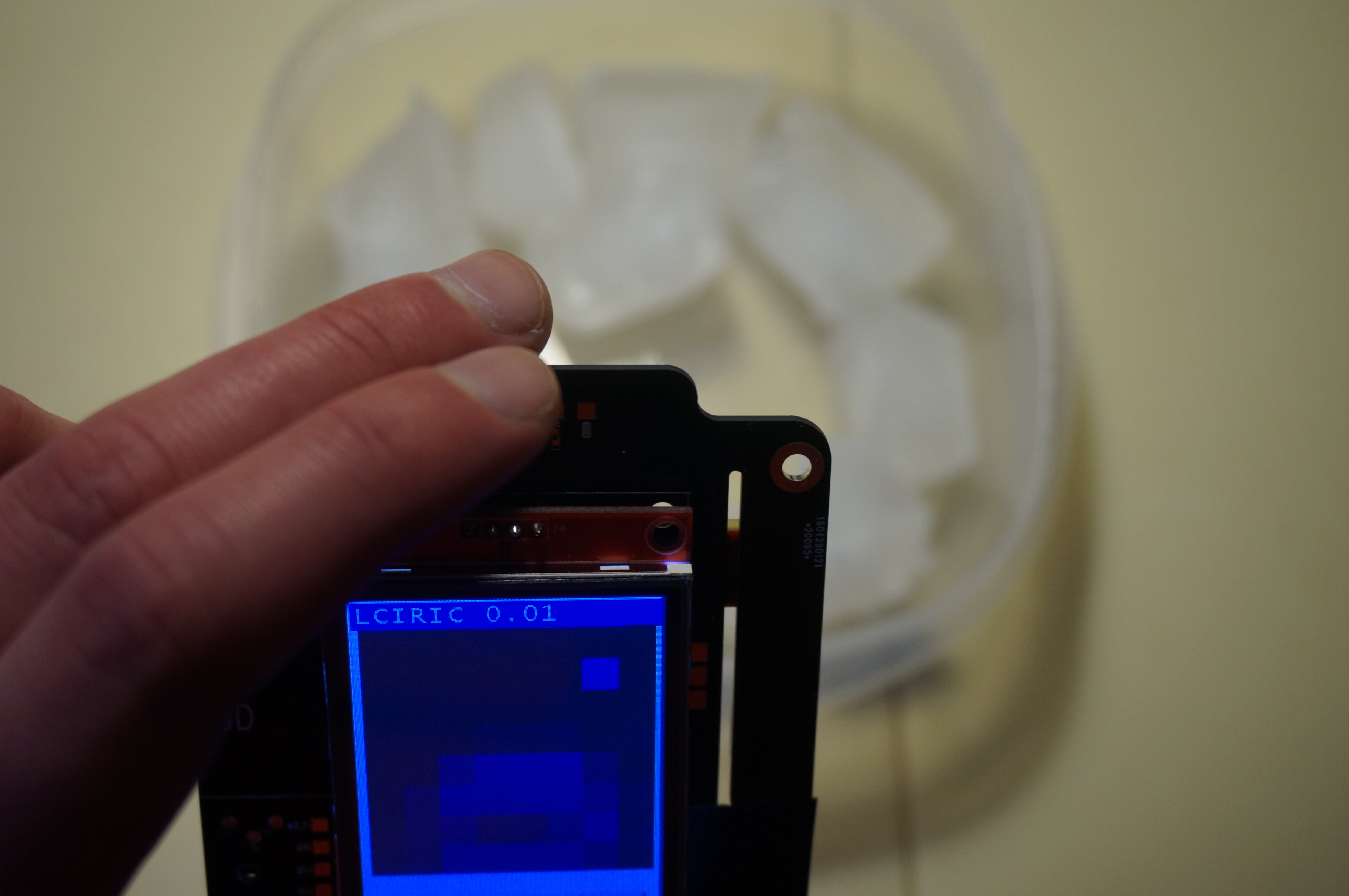
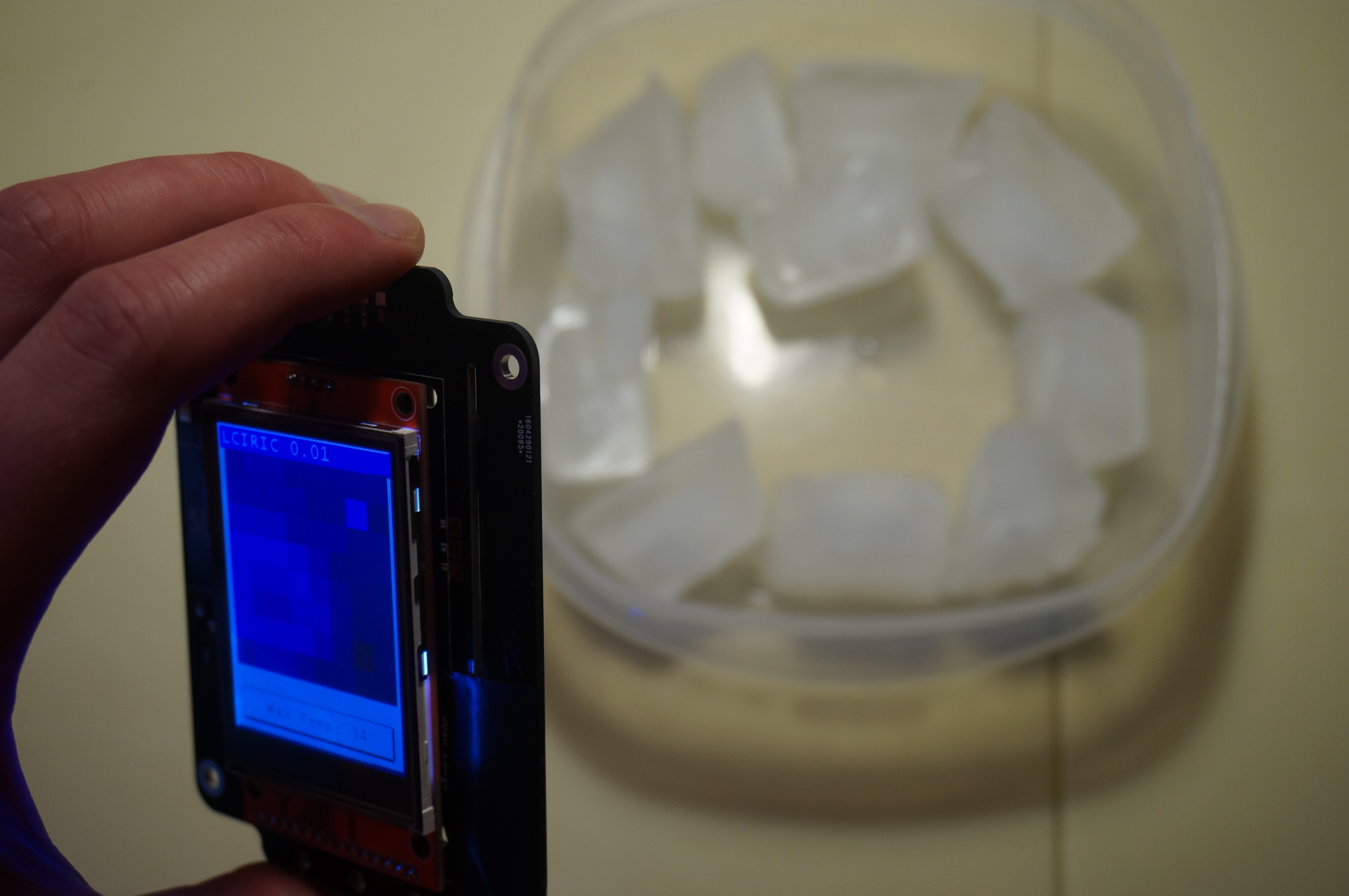
    I've gotten the GridEYE sensor working on my prototype board. I've implemented a simple linear mapping of -25 - 100 degrees = 100% blue to 100% red. It seems like a linear mapping doesn't produce entirely intuitive results, and doesn't photograph well, either. My intention is to tweak the display mapping quite a bit. I would ultimately like to implement the standard "iron" color scheme that is common on commercial thermal imagers, and have several different color scheme options to select from.

    Unfortunately, the sensor I have seems to have two dead pixels. This means that the maximum temperature reported is always at least 34 degrees. I may eventually implement a software feature to disable dead pixels and take the average of the pixels around them in order to fill in the resulting blank space.

    Here's what it looks like when looking at two resistors dissipating about 5W, as well as some ice cubes.

  • LCD Display Working

    Josh Lange05/25/2016 at 06:18 0 comments

    I've been working on getting the LCD display working. This display uses an ILI9341 controller which has built-in RAM. The display is interfaced with the microcontroller using the SPI bus running at 24 MHz. I am using the uGUI library for this project, and I currently have one of the example projects up and running. Since the microcontroller doesn't have anywhere near enough RAM for an internal frame buffer, the image is drawn to the display directly, one element at a time. I've implemented the uGUI hardware acceleration functions, and made a few improvements, so that straight lines, rectangles, images, and text are sent in sections, rather than pixel-by-pixel. It currently takes between 0.1-0.2 seconds to draw a full image. This does depend significantly on the complexity of the interface being drawn. (Filling rectangles is faster than drawing text, for example.) In addition, I am currently operating the SPI bus in blocking mode, so the CPU is locked up while the rendered region is being sent to the display. There is potential for significant speed improvements if DMA were implemented so that the next region could be rendered while the current region is being pushed to the display over SPI. It's on my to-do list.

    Next up, I'm going to try to get the GridEYE sensor working.

  • First Boards

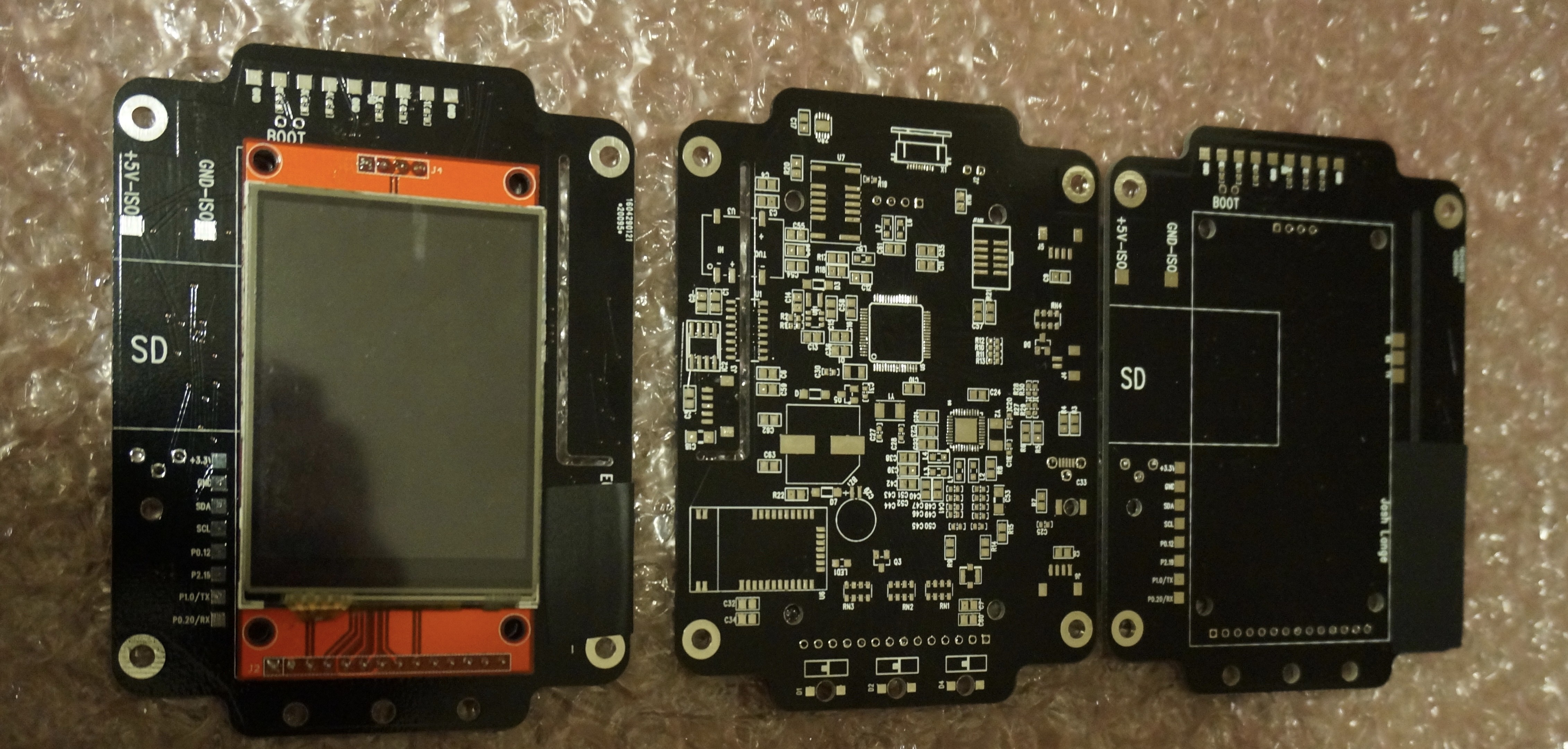
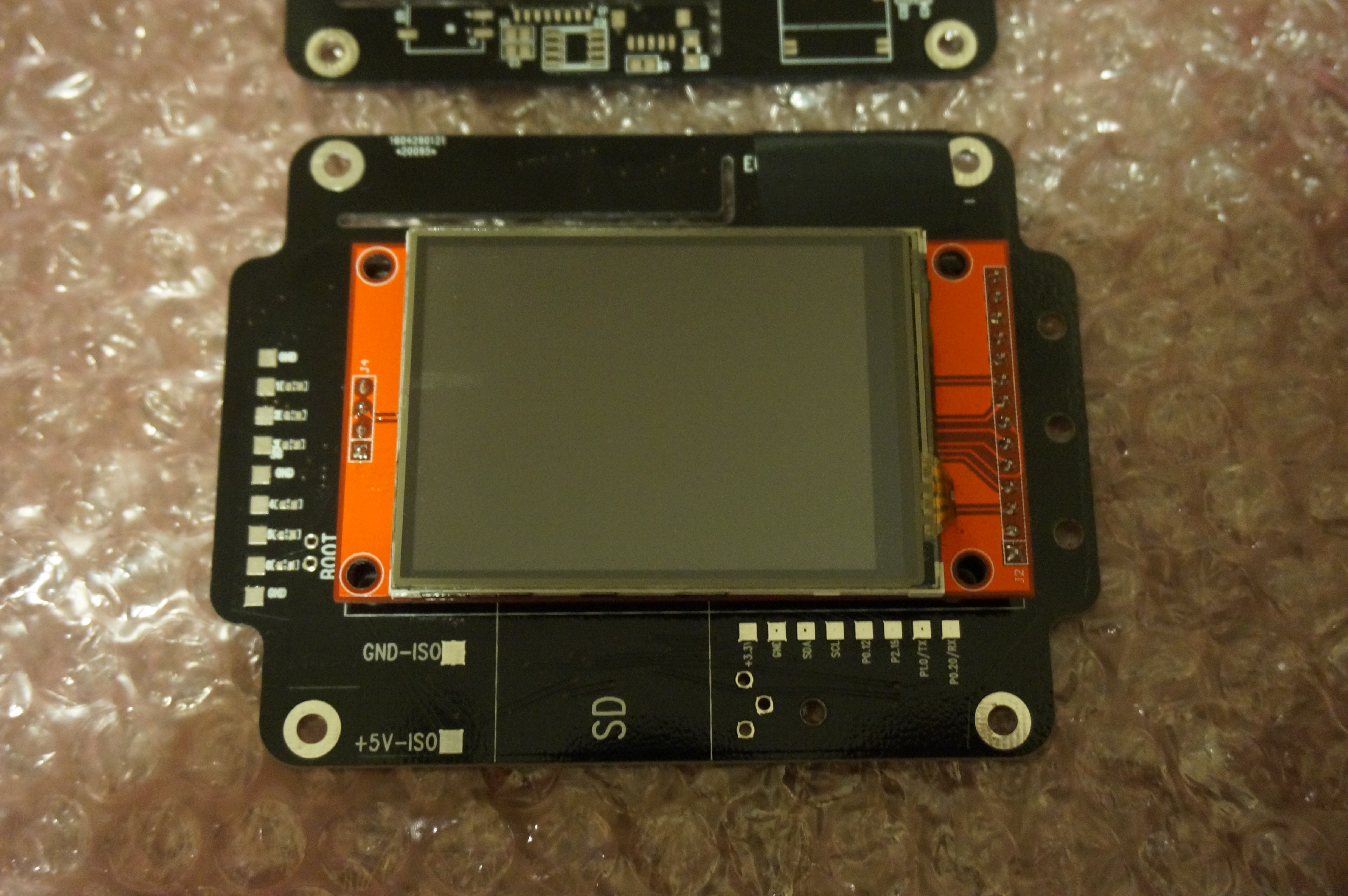
    Josh Lange05/16/2016 at 05:51 0 comments

    I added the GridEYE sensor footprint to another board I'm putting together for a customer. I just got the boards and the parts should arrive this week. This board uses the same CPU and LCD that I plan on using for this project. This will give me the opportunity to test the following things before making the final version of the boards:

    • CPU
    • LCD
    • Touch Controller
    • SD Card
    • USB
    • GridEYE Sensor

    I have also been doing some initial software prototyping using a dev board; I hope to have an update on that in the next couple of days.

View all 4 project logs

Enjoy this project?

Share

Discussions

Trailhead wrote 08/04/2016 at 16:12 point

Fascinating project.  Is the hardware design mature enough that someone else could build one and tinker with firmware?

  Are you sure? yes | no

patrik wrote 08/04/2016 at 06:23 point

Nice! Where do you buy the sensor? 

  Are you sure? yes | no

Similar Projects

Does this project spark your interest?

Become a member to follow this project and never miss any updates