Grayson Schlichting
-
But the Silicon Labs Devices means Spinning a PCB...
07/11/2016 at 08:14 • 0 commentsTo have a purpose-built heart rate monitor that sends its data telemetry out BLE using the components found on the Thunderboard will require a custom built PCB.
A viable (read: wearable) solution that could be made from off-the-shelf componentry for experimentation could be assembled that uses light-through-skin vs. the electrode method of the not-so-comfortable Polar solution I began with.
Using parts made by Adafruit such as Trinkets and other new Arduino-compatible boards they continuously design and build, along with something like the "Pulse Sensor Amped" by pulsesensor.com, I think a more comfortable "prototype" could be assembled which would include the pulse sensor, a processor, and perhaps still the nRF24L01+ transceiver for the headboard alert. But if you're going to "wear" the data processing engine anyway, then the vibrating motor could be included onboard having the same "waking impact" just as the silent alarms do on a FitBit.
Check out the Pulse Sensor Amped "kit" sold by Adafruit: https://www.adafruit.com/products/1093
And a project using it in their LEARN section: https://learn.adafruit.com/pulse-sensor-displayed-with-neopixels/the-code?view=all
I think this is where I will take the next prototype whilst working with Silicon Labs and Arrow on a version that would be the most comfortable and power efficient custom design.
-
Silicon Labs Thunderboard to the Rescue!
07/11/2016 at 07:49 • 0 commentsUnlike the Silicon Labs Sensor Puck, which had a 3rd party light/UV/Pulse device (and a non-Silicon Labs Bluetooth chip on the backside), enter the Silicon Labs "Thunderboard Wear ARM".
This little guy, again a demonstration / development platform, is PACKED with goodies, and this time they are all Silicon Labs devices.
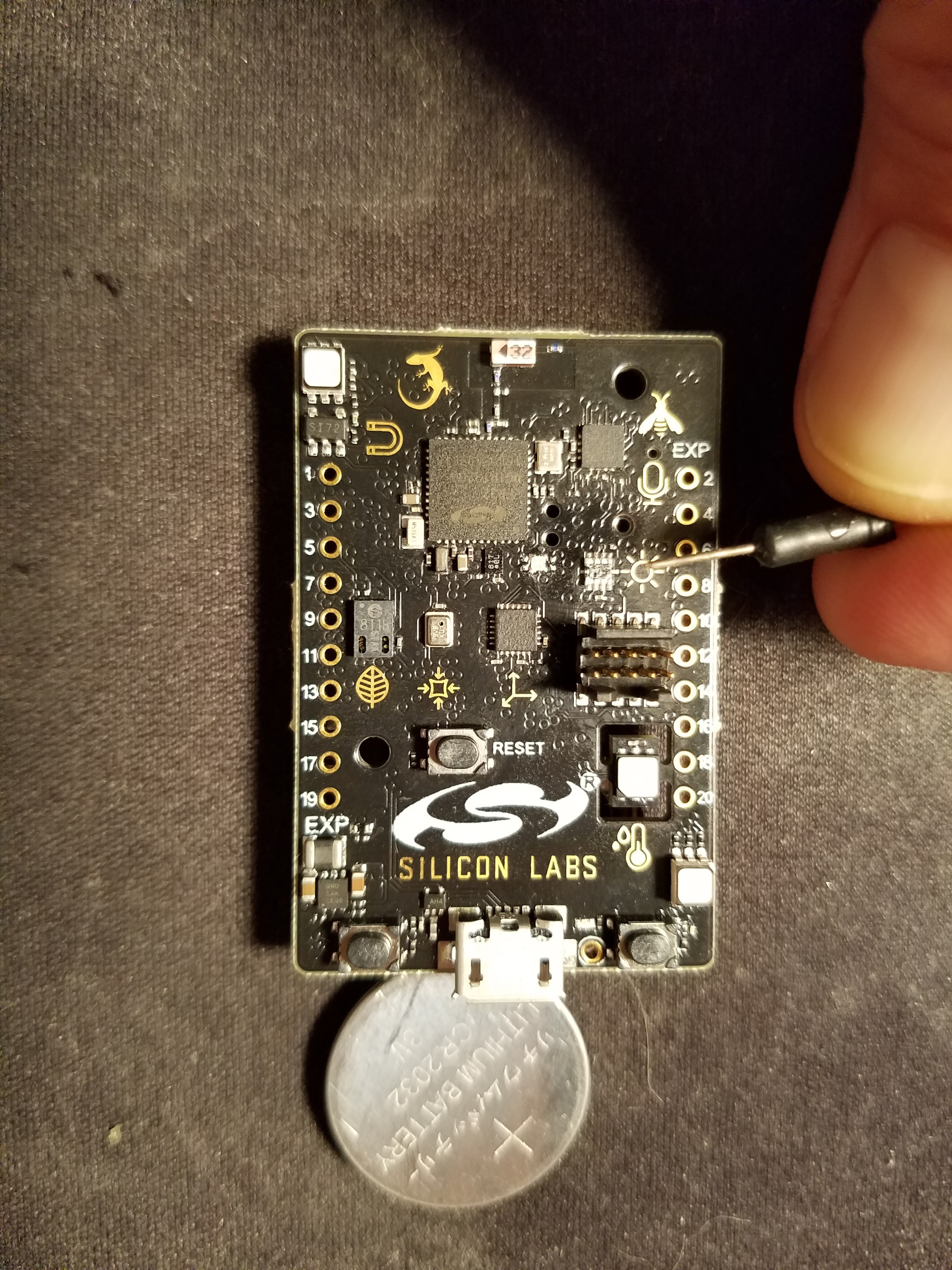
I am pointing a breadboard jumper at the ambient/UV/Pulse Detector on this guy (it's TINY):
![]()
Due to the header right next to it (and the fact I have only had it for a couple of weeks), I have yet to "wear" this, but it has the same functionality as the Puck; place your finger over that 8-pin device and you get heart rate.
It uses the Silicon Labs BGM111 Bluetooth Smart Module which has its own stack in a certified module. Also, devices like the BGM111 (and other sensors on the Thunderboard) can run in an autonomous manner where they can do "work" without waking the host processor. The components and architecture of this family of devices on the Thunderboard will yield the lowest power wearable for this application (and they have the power performance monitoring tools to prove it!).
Every wearable hacker should get one of these little gems when they hit the market later in July. The Toolchain for it is incredible, and you can write code in a simple "BASIC-like" language to control it, and then do real-time power profiling. Silicon Labs rules on this suite of wearable and small form factor monitoring goodies.
-
Enter the Silicon Labs Sensor Puck
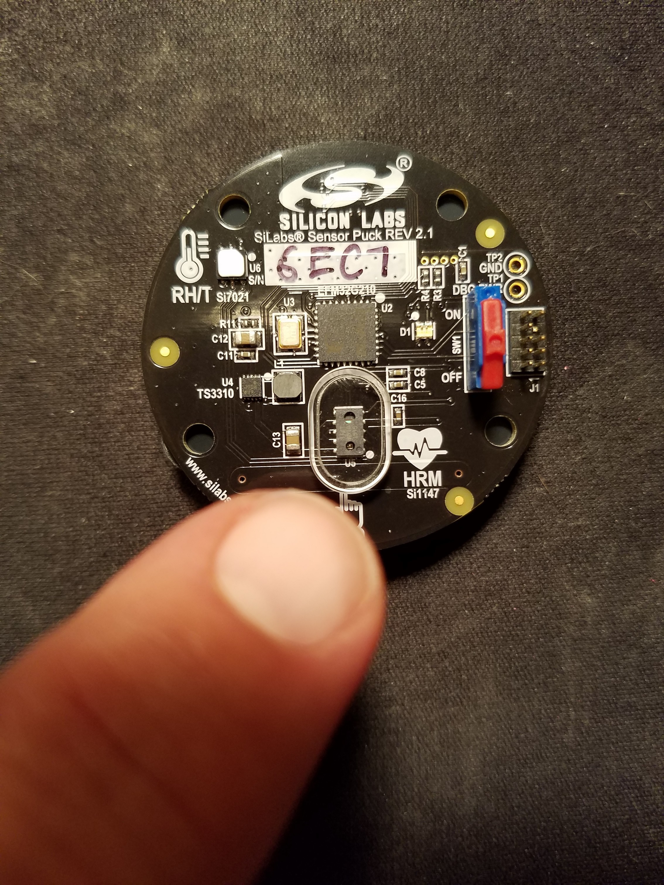
07/11/2016 at 07:28 • 0 commentsEnter the Silicon Labs "Sensor Puck" which includes a dual-mode light sensor which can measure ambient light, UV light for UV exposure accumulation, and when you place your finger over the plastic-covered LED assembly (at the bottom of the Puck), it changes modes and goes into pulse rate monitoring (ala FitBit).
https://www.silabs.com/products/sensors/Pages/environmental-biometric-sensor-puck.aspx
U5 is under a plastic shield, and it can monitor Heart Rate, and send the data out using Bluetooth BLE. I have actually been able to strap this to myself such that the window I am pointing at is close enough for the Puck to go into Heart Rate mode (J1 is a bit painful so it took some clever work with velcro strips and bandage tape).![]()
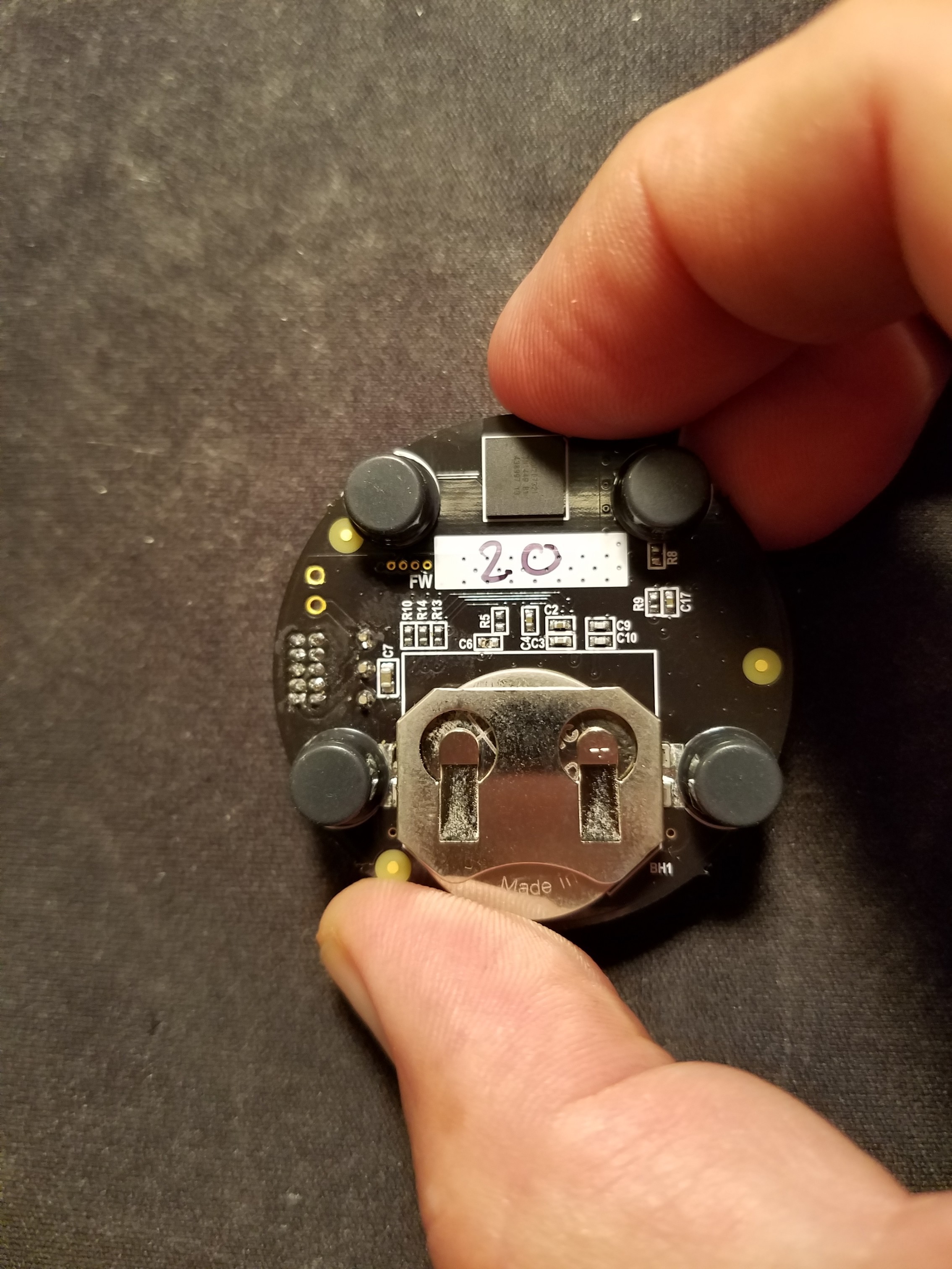
The Puck is a bit too large to wear, but it's only a demonstration platform. Here is the back side where you see a CR2032 battery, and at the top the Bluetooth Chip:
Obviously not ideal as a purpose-built monitor! Also, the LED light/UV/Pulse sensor on the front are from various vendors and not designed by Silicon Labs.![]()
-
Why Not a FitBit Charge HR?
07/11/2016 at 06:48 • 1 commentI have one of these, and wear it 24/7. It sends out a constant "greenish" pulse of light from 2 LEDs to accomplish its measurements.
There are two problems:
1) The FitBit unit itself averages your heart rate in its normal operating mode. You can press and hold the button on the side to go into "Workout Mode" and it will read (and log) continuous heart rate measurements.
2) FitBit uses Bluetooth BLE to send its telemetry, but it is encrypted and proprietary. The only way to get this data is after it has made a trip through BLE to your computer or SmartPhone (with the FitBit App) and then is transmitted to the FitBit "cloud."
This is not ideal, because there is a time delay, and API calls out to the Internet must be made to get (then parse) this information.
-
Using a Polar Heart Rate Monitoring Chest Band
07/11/2016 at 06:37 • 0 commentsI started out with the Polar Chest Band which transmits heart rate wirelessly (via Bluetooth or a proprietary RF method). I used the Non-Bluetooth model to simplify the project since the receiver board is just that; it requires no setup or programming. It just sends out a 20ms. pulse (ha ha) on each heartbeat it receives from the band.
Starting point was this:
Heart Rate Educational Starter Pack with Polar Wireless Sensors
from Adafruit: https://www.adafruit.com/products/1077
The Polar bands use electrical pick-up pads to detect heart beats, and you have to wear it just under you pectoral region. It's a bit uncomfortable, but it was where I started.
![Heart Rate Educational Starter Pack with Polar Wireless Sensors]()
This picture is from Adafruit.com. With the parts included, you can wire it up and see your pulse on that (jumbo) red LED. Pictured are a battery holder for 3V to power the receiver board (the Polar has an internal CR2032 for powering the EKG sensor and the transmitter). You wear the sensor band as described across your chest, and what is pictured left and above the band is the adjustable elastic band that holds it around your torso.
The resistor is for current-limiting the LED, and you can see the Receiver Board which has only 3 pins: power, ground, and out. Snap off all but 3 of the header peices, solder them to the RX PCB, and plug it all into the provided Protoboard and you can watch the LED flash as your heart beats.
For my first prototype, I sent the Receiver's Out pin to a GPIO pin on an Adafruit Trinket (small Arduino compatible board). That's where the sensor is monitored, filtered, and analyzed. When it detects a rise in heat rate of x% over time (t) then "something" is happening. If you are having a dream so intense that it causes you to sweat, then your heart rate WILL increase. Your "x%" and "t" will vary. For the final build, I am considering perhaps 2 potentiometers for setting this.
When a threshold is detected, then the Trinket is used to drive the nRF24L01 transceiver which wirelessly connects to the "alerting device" - in my case, I have it drive a small vibrating motor stuck to my headboard which resonates loud enough to wake me up.
I used this: https://www.adafruit.com/products/1201
I am happy with the "receiving-side" of the project, but really needed a way to measure heart rate more "comfortably."
Dream Catcher
Life-changing circumstances led me to begin having Nightmares in which I would wake up finding my pillow soaking wet, and vivid memories it.