 ottoragam
-
1Step 1
Connector Options / Assembly
The board supports multiple connector types:
 PMinMO: A 2x5 header soldered on the edge with the PCB
inserted between the pins which are soldered along the face of the pads.
Used with a 10 conductor ribbon cable and IDC female 2x5 connector, this
option has the advantage of a ground line between each signal for very low
noise and long runs.
PMinMO: A 2x5 header soldered on the edge with the PCB
inserted between the pins which are soldered along the face of the pads.
Used with a 10 conductor ribbon cable and IDC female 2x5 connector, this
option has the advantage of a ground line between each signal for very low
noise and long runs.
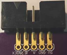
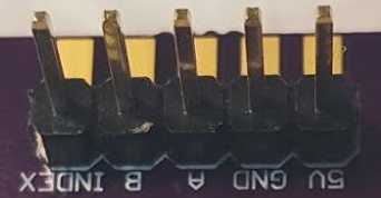
To install a PMinMO shrouded header, align pin one (marked with the triangle on the shroud) with the pin marked "INDEX" on the edge of the PCB, with one row of pins along the top surface mount pads, and the other row along the bottom pads (see picture below). The notch in the shroud should be on the top side of the PCB, where the chip is mounted. Solder a single pin, then check alignment and solder on the rest. To avoid overheating the plastic and warping the pin positions, solder one pin on the top, then the opposite pin on the bottom, alternating back and forth. It also helps to have a female IDC connector cable plugged into the header while soldering.
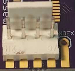
Single Row: A Molex KK or 1x5 header soldered through hole can also be used. In this case, it is best to use a polarized header and cable so that it can not be plugged in backwards.
Bare Wires: Or you can just solder the wires directly into the holes. Some strain relief, such as threading the wires through an unused mounting hole, would be wise.
Installation
Magnet:Attach the magnet disk to the part where you need to sense angular position, e. g. front or back of the motor shaft, lead screw, ball screw, etc. For testing and alignment, the magnet will stick to any steel shaft, but vibration and shock will dislodge it. A two part epoxy is recommended for a permanent mounting. After affixing the magnet, slowly turn the shaft to ensure it is centered and will not vibrate loose at higher speeds.
Mounting:
The board must be mounted so that the chip is close (less than a half inch) to the magnet and centered over the magnet’s axis of rotation.
The board supports M3 and #4 screws. At least two screws (diagonally) should be used to hold it in position. Three screws are best. Click the picture to right for a detailed mounting diagram.
Turn the shaft where the magnet is attached. If the board is centered and close enough to the magnet, the onboard LED should dim and brighten as the magnet rotates in front of the IC.
Operation
A microcontroller, such as the Microchip PIC (as used on our BOB PID controller) or ATmega328p (Arduino Uno, Arduino Nano, several other Arduino variants), should be present to read the STEP/DIR signals from the machine controller, read a quadrature encoder input and perform the calculations required for a PID control of the motor position. For more on General PID theory see
http://www.cds.caltech.edu/~murray/books/AM05/pdf/am08-complete_22Feb09.pdfThe PID controller, such as the MassMind BOB PID will need to be tuned.
Massmind.org Abosolute/Incremental Rotary Encoder
Commercialy available, partially assembled low cost encoder module

Discussions
Become a Hackaday.io Member
Create an account to leave a comment. Already have an account? Log In.