-
All your base are belong to us
07/10/2016 at 01:15 • 0 commentsHello,
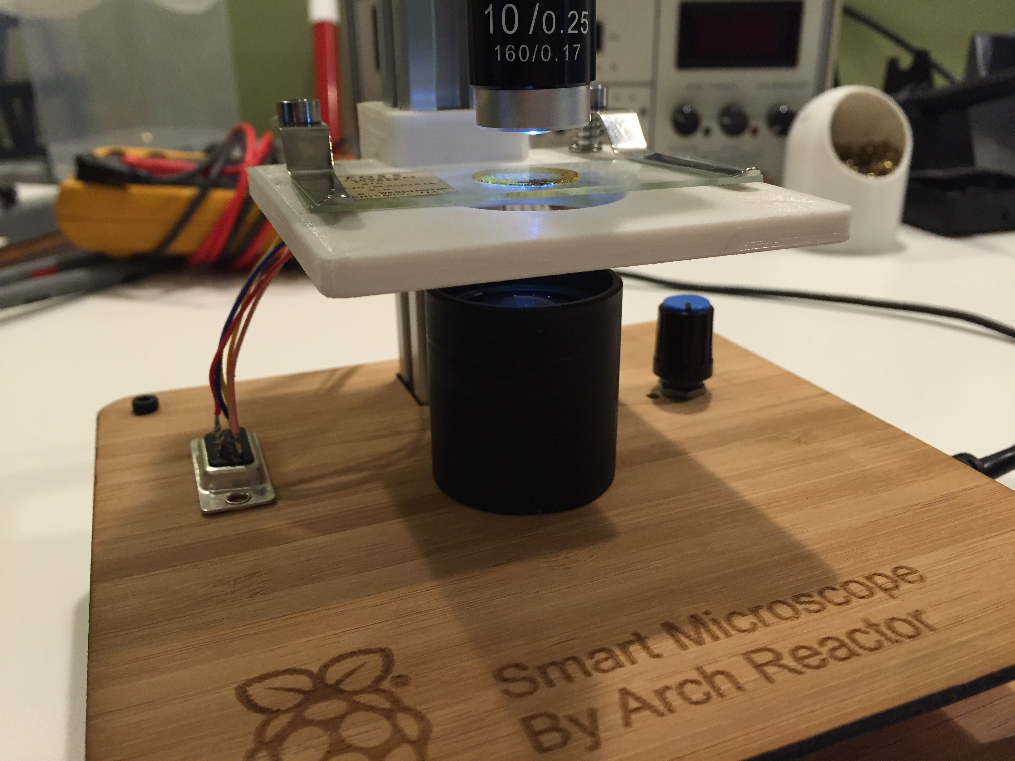
We have been busy with the electronics side of the scope. We have for a while now been wanting to place the electronics in a small enclosure that would ether attach to or lay beside the scope. However someone had a idea to make the base what holds the scope upright and the electronics.
So I laser cut some fancy bamboo plywood into upper and lower plates that sandwich the electronics between them.
The electronics are a Adafruit battery charger that links with a 2500 mah li-ion battery. The output feeds a newly acquired 5 amp step up DC- DC converter. The output 5 volts from the converter runs the LED, Pi 3 and Stepper motor. I added a manual 1k ohm potentiometer to the LED as I like the feel of a mechanical dimmer for the main light.
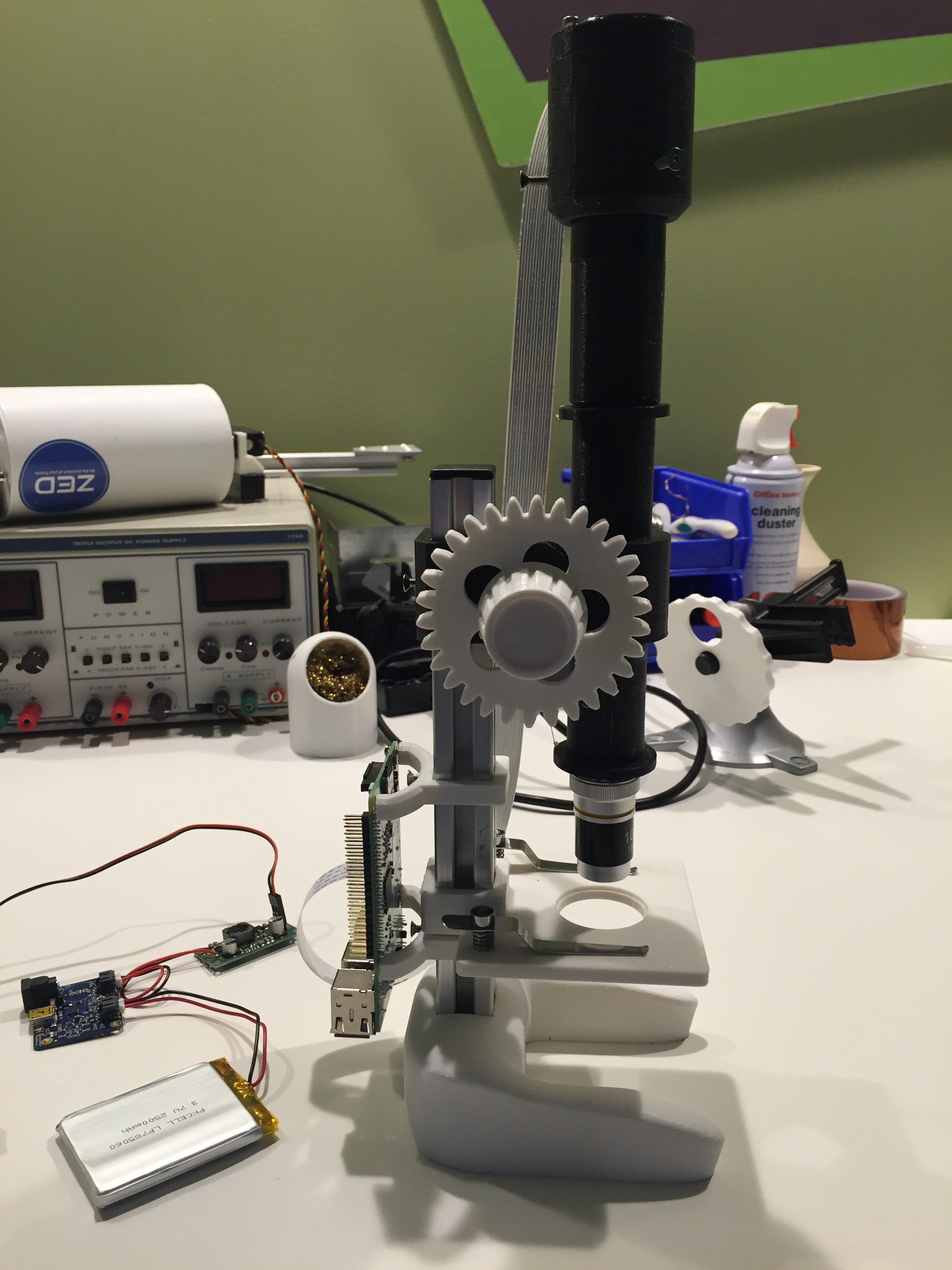
The top most layer is very clean and is only broken up by a few elements. Though the DB9 motor power connector feeds though nicely and the black lens assembly ties well into the rest of the microscope.Here is a picture of the final look of the scope with the newly added bamboo base with integrated electronics. I will be adding the files over the next hour or so. This way you can make your own base if you would like.
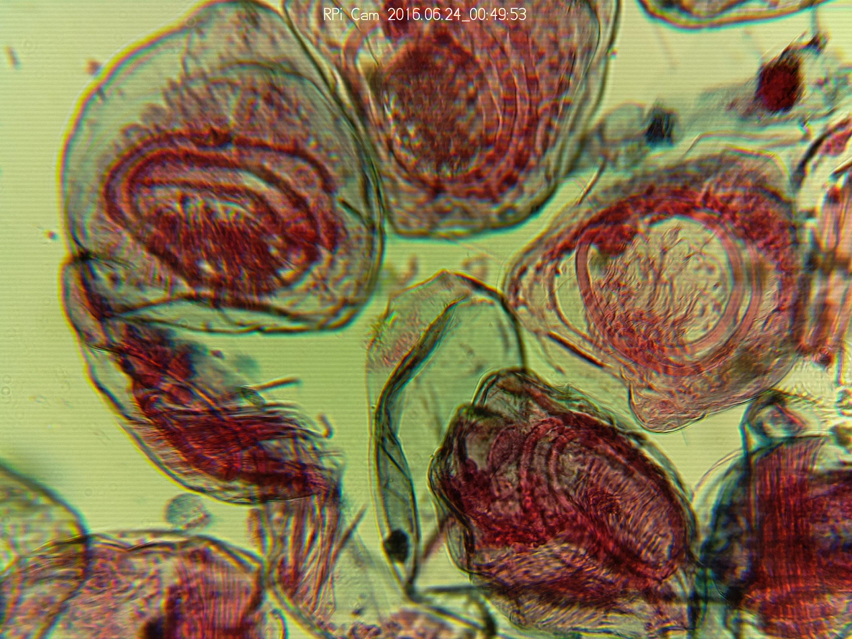
![]() The images are from the updated light and base are looking very clear. Above is a picture of Taenia pisiformis or commonly called the rabbit tapeworm. You can find out more information here.
The images are from the updated light and base are looking very clear. Above is a picture of Taenia pisiformis or commonly called the rabbit tapeworm. You can find out more information here. -
Stepper control from interface
07/01/2016 at 02:55 • 0 commentsTonight we were able to attach the stepper to the scope and control it via the web interface.
The geared stepper has a full rotation of 513 steps, This translates to 1,539 steps for a large gear rotation. We have found that we roughly have 1 2/3 large gear rotations. or 2,565 steps for full travel of the z axis.
Below is a video explaining the scope:
-
Kansas City Maker Faire
06/27/2016 at 20:56 • 0 commentsThe newest revision of the Microscope went to the 2016 Kansas City maker faire. There was a huge turn out and a lot of people liked the scope.
For those who asked for a updated parts/files they have now been uploaded to this page. If you have any questions on building your own don't be afraid to ask.
-
Microscope V2
06/24/2016 at 02:38 • 0 commentsHello,
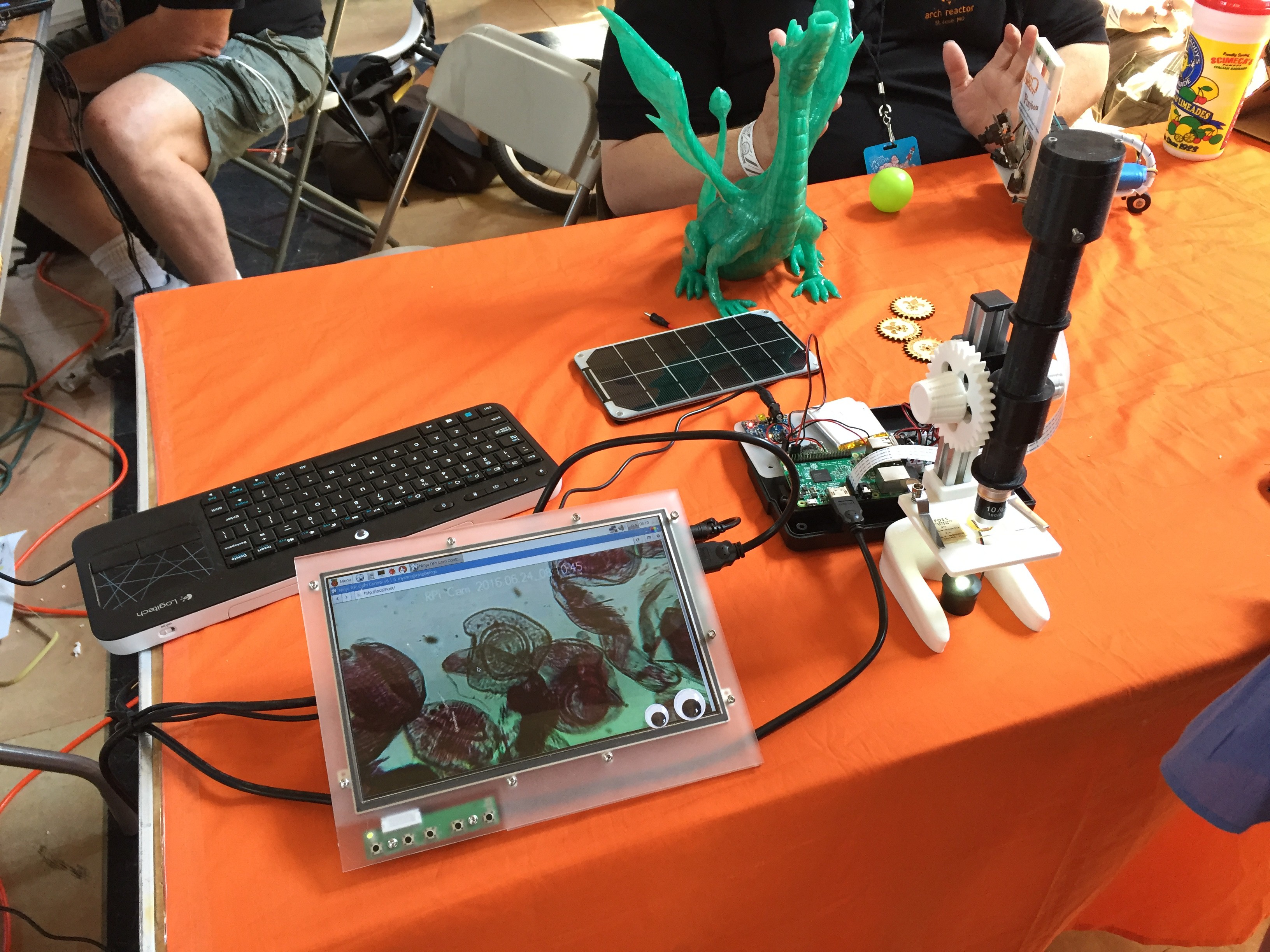
We completed a major redesign of the microscope and today we are proud to release the new version of the scope. There are many new features that realign the design to a more classical look. This has many design features that I have listed below. The scope was designed to be light, easy to build, low cost, and compact.
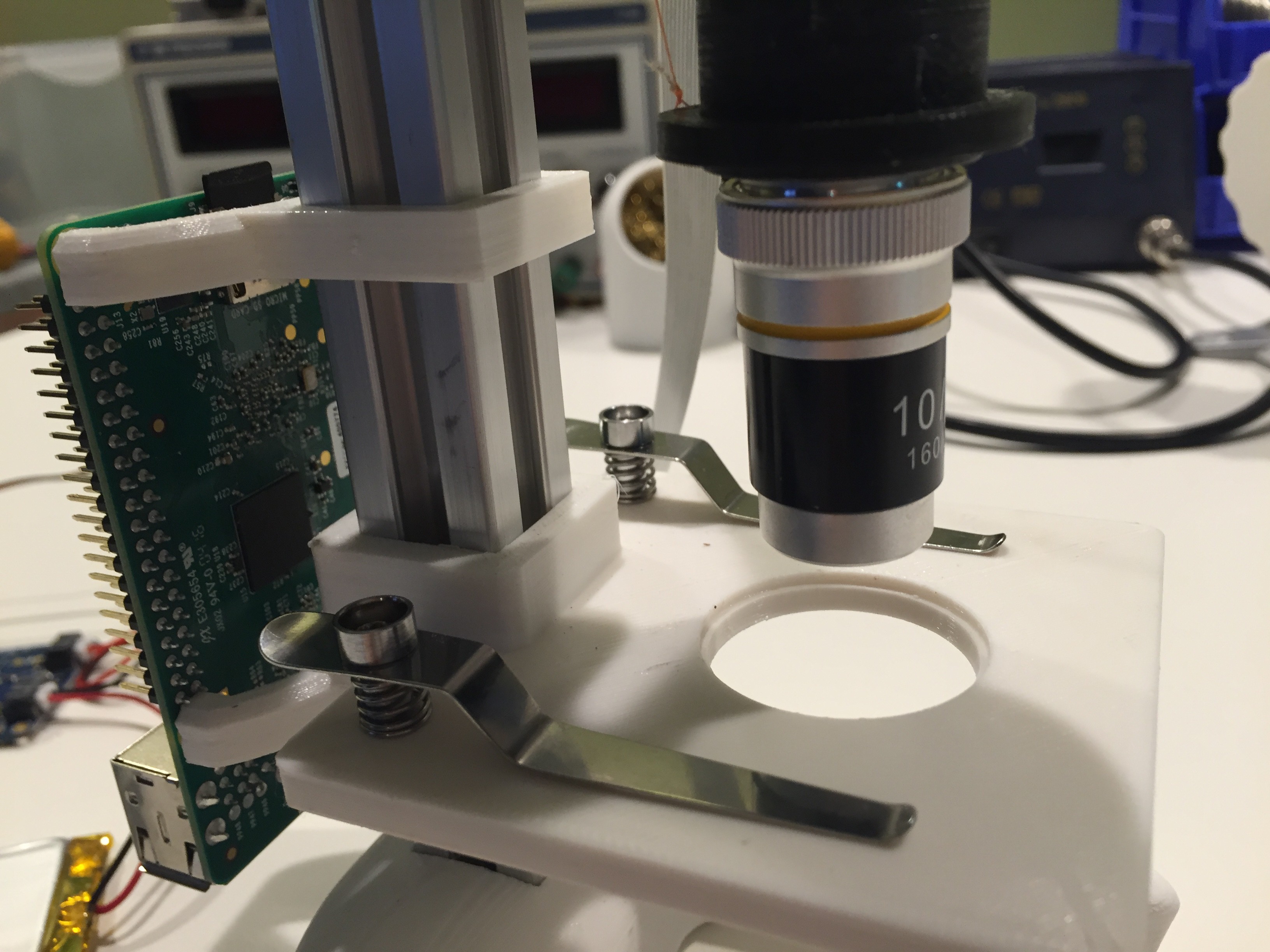
- Uses common microscope eyepiece and objectives. At the moment that includes a 10x eyepiece and a 10x objective for a total of 100x magnification.
- It features a slide platform that was printed solid with added spring loaded metal slide holders.
- Side facing focusing knobs on smooth running metal ball bearings.
- A 160mm 3D printed tube to match the focal lengths of the glass lenses.
- Built in Li-poly battery to run the scope with out power infrastructure, Also a large solar array to power it in remote areas.
Be sure to like are project and as always comments are welcome!
Behold the microscope V2:
I will be posting updated 3D print files soon so be on the lookout!
Also for your viewing pleasure the first few images from the new microscope:
The image below is a slide of Clam, Glochidia - is a microscopic larval stage of some freshwater mussels, aquatic bivalve mollusks in the families Unionidae and Margaritiferidae, the river mussels and European freshwater pearl mussels.
![]()
This next image is of a onion root tip:
![]()
-
User Interface - Stepper controller
06/17/2016 at 02:43 • 0 commentsTook the stepper motor controller script and connected it to the web interface.
-
*Project update*
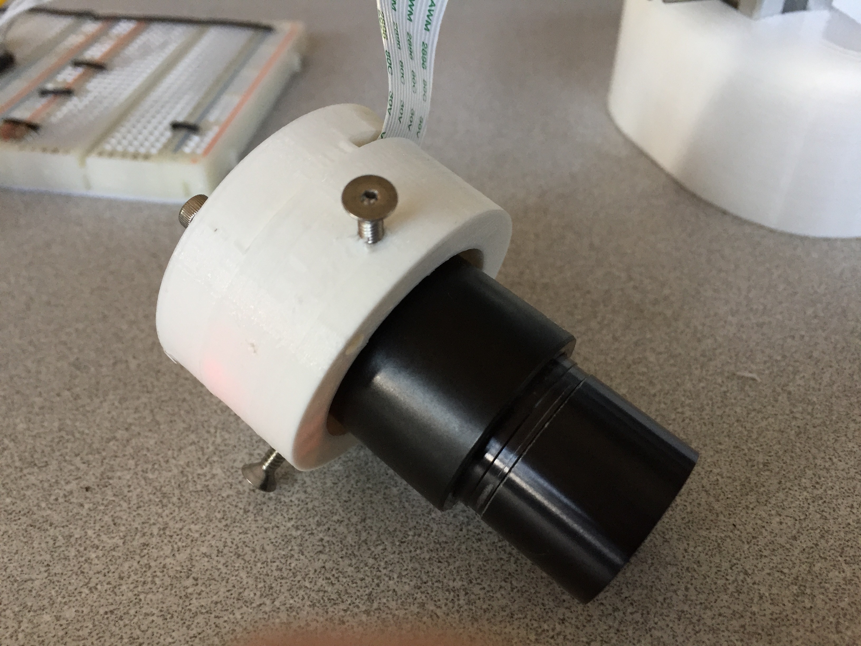
06/16/2016 at 22:58 • 0 commentsWe apologize for the radio silence however we have still been hard at work the the microscope. Apollo hs designed a 3D printable mount so you can adapt the Pi camera to a standard microscope. Files are "top of camera mount.stl" and "bottom of camera mount.stl".
quick note on assembly: The camera works best with a microscope if you remove the lens from the camera before assembling. The assembly used standard 3mm hex head screws for assembly and a piece of double sided tape on the top of the camera board to finish out.
We will be posting a few nice still shots of the camera in action in a up and coming project log. We have a meeting tonight to work on the UI of the remote feed and integration of the stepper control.
*Please be aware all of a the files are in a prototype stage so be carefully using them as they are subject to change.
-
Wiring the steppers to the controllers
05/31/2016 at 16:01 • 0 commentsYou will need to determine the wire pairs for each coil on the motor you plan to use. The most reliable method to do this is to check the datasheet for the motor.
For a 4-wire motor, take one wire and check its resistance against each of the three remaining wires. Whichever wire shows the lowest resistance against the first wire is the pair mate. The remaining two wires should show similar resistance between the two of them.
For a 6-wire motor, you will need to determine which of three the wires go together for one coil. Pick one wire, and test this against all other wires. Two wires should show some resistance between them and the first wire picked, while the other three will show no connection at all. Once the three wires for one coil have been determined, find two of the three that show the highest resistance between them. These will be your two coil wires. Repeat for the second group of three wires.
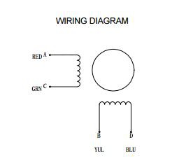
Once you have determined the coil wire pairs, you will need to attach them to the Easy Driver. The first coil pair should be plugged into Coil A+ and Coil A-, while the second coil pair plugs into Coil B+ and Coil B-. There is no polarity on the coils, so you don’t need to worry about plugging in a coil backwards on the board. In our example, we are using a 4-coil motor. The connections between the Easy Driver and motor are as follows.
Source: Sparkfun electronics hookup guide
Below is the code used to test the motor Step two was modified so that if you do not insert a number for steps the code will still run.
You can also run the following in the terminal if you name the program countingsteps.py
sudo python countingsteps.py left 1600#Step 0: Preamble #------------------------------------------------------------------------ #------------------------------------------------------------------------ #Program Title : countingsteps.py #Code Written by: Salty Scott #Current Project: www.rowboboat.com #This code is a very basic example of using python to control a spark fun # easy driver. The spark fun easy driver that I am using in this example # is connected to a 42HS4013A4 stepper motor and my raspberry pi. Pin 23 # is the direction control and pin 24 is the step control. I am using # these components in the www.rowboboat.com project version 2.0 and I # hope someone finds this a useful and simple example. # This program expects two arguments: direction and steps # Example usage: sudo python easy_stepper.py left 1600 # The above example would turn a 200 step motor one full revolution as by # default the easy driver 4.4 is in 1/8 microstep mode. #------------------------------------------------------------------------ #------------------------------------------------------------------------ #Step 1: Import necessary libraries #------------------------------------------------------------------------ #------------------------------------------------------------------------ import sys import RPi.GPIO as gpio #https://pypi.python.org/pypi/RPi.GPIO more info import time #------------------------------------------------------------------------ #------------------------------------------------------------------------ #Step 2: Read arguments #------------------------------------------------------------------------ #------------------------------------------------------------------------ #read the direction and number of steps; if steps are 0 exit try: direction = sys.argv[1] steps = int(float(sys.argv[2])) except: direction = 'left' ## new line to set default direction steps = 0 #print which direction and how many steps print("You told me to turn %s %s steps.") % (direction, steps) #------------------------------------------------------------------------ #------------------------------------------------------------------------ #Step 3: Setup the raspberry pi's GPIOs #------------------------------------------------------------------------ #------------------------------------------------------------------------ #use the broadcom layout for the gpio gpio.setmode(gpio.BCM) #GPIO23 = Direction #GPIO24 = Step gpio.setup(23, gpio.OUT) gpio.setup(24, gpio.OUT) #------------------------------------------------------------------------ #------------------------------------------------------------------------ #Step 4: Set direction of rotation #------------------------------------------------------------------------ #------------------------------------------------------------------------ #set the output to true for left and false for right if direction == 'left': gpio.output(23, True) elif direction == 'right': gpio.output(23, False) #------------------------------------------------------------------------ #------------------------------------------------------------------------ #Step 5: Setup step counter and speed control variables #------------------------------------------------------------------------ #------------------------------------------------------------------------ #track the numebr of steps taken StepCounter = 0 #waittime controls speed WaitTime = 0.01 #------------------------------------------------------------------------ #------------------------------------------------------------------------ #Step 6: Let the magic happen #------------------------------------------------------------------------ #------------------------------------------------------------------------ # Start main loop while StepCounter < steps: #turning the gpio on and off tells the easy driver to take one step gpio.output(24, True) gpio.output(24, False) StepCounter += 1 #Wait before taking the next step...this controls rotation speed time.sleep(WaitTime) #------------------------------------------------------------------------ #------------------------------------------------------------------------ #Step 7: Clear the GPIOs so that some other program might enjoy them #------------------------------------------------------------------------ #------------------------------------------------------------------------ #relase the GPIO gpio.cleanup() #------------------------------------------------------------------------ #------------------------------------------------------------------------ -
One step closer!
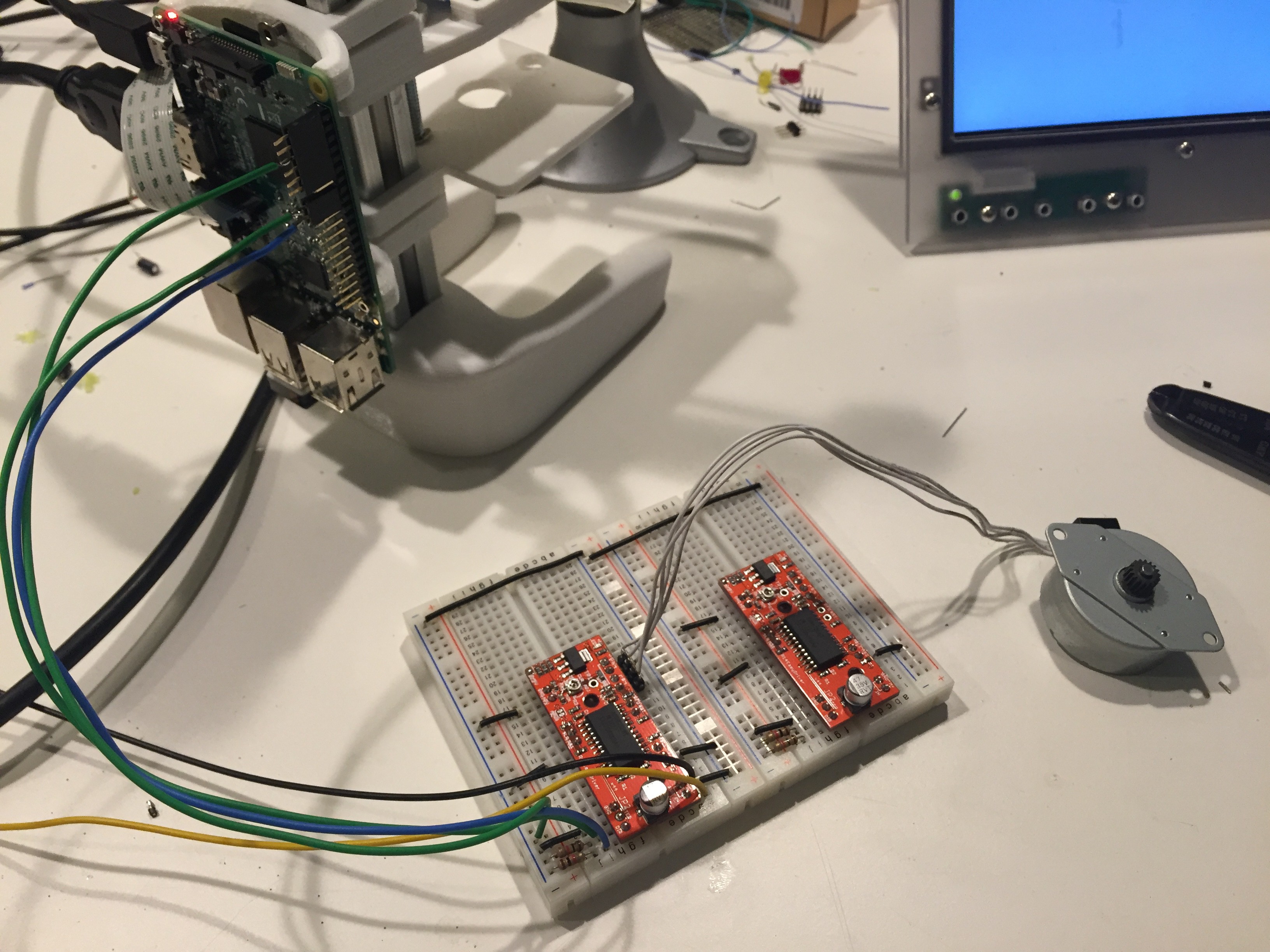
05/29/2016 at 19:43 • 0 commentsI have been busy this weekend as I have received the stepper controllers. So far I have wired them into the pi. This step took a few as I wanted to take my time making the breadboard look nice. I have been digging into the software side of the motor control a bit and I have installed RPi.GPIO and have been working on a python script to test the motor. More to come on Thursday when Ninju looks at what I have done and makes it interface with the web.
A few tips when using the easy drivers:
- Careful to wire all the grounds together
- Do not connect or disconnect a motor while the driver is energized. This will cause permanent damage to the A3967 IC.
- To wire in the Steppers please follow the newest project guide.
We purchased the drivers here for there low price of $8.92 dollars each.
http://www.robotshop.com/en/easydriver-stepper-motor-controller.html
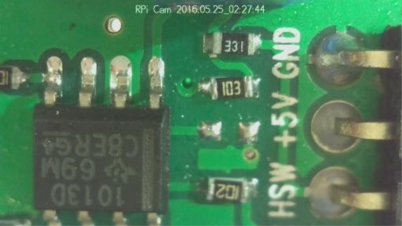
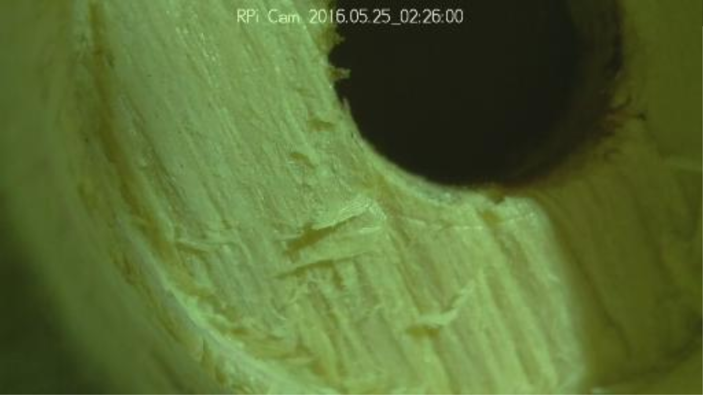
Also we we able to get a few more very clear screen shots from the new setup. Below is a pictures of a circuit board and wood fibers
![]()
![]()
-
Adding software features
05/28/2016 at 18:04 • 0 comments*Update on the software side from Ninju Bohra *
After getting the basic software running to allow us to share what the microscope was viewing on a website I am now adding more features to the software.
One feature that I will contribute the idea of a "fullscreen" page so that it can show the microscope image on a projector without all the control elements.
-
Sharing the Microscope with the World
05/20/2016 at 02:15 • 0 commentsAfter a basic setup of the microscope assembly we then started to look at the software features. After our initial success with a software routine that shows the camera 'preview' to a local monitor, I started to investigate options for viewing/sharing the image across a wifi signal to a browser connected to the Raspberry PI.
I looked around for an open source framework from which to start our custom development. After some searching I found the Rpi Camera Module that seems to be a good starting point.
Installing the Software
I was able to download the software from the Github site and followed the installation instructions. During the installation I realized that I was not running as a elevated user (root) and the installation failed. Fortunately the software came with a remove script and I was able to uninstall the software and then re-installed the software running as root.
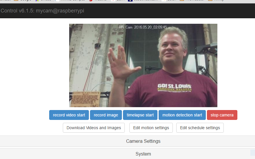
After rebooting the PI, to startup the new webserver software, I was able to see the main page of the software:
![]()
Viola!!!
Now we need to improve on the software to do the features we want.
Gotchas
One thing to note, when running the RPi-Camera-Module application it will acquire the PICamera for its purposes and so afterwhich you are not able run a second process to access the camera
Internet of Things Microscope
We are updating the microscope using open source materials to make microscopy accessible globally
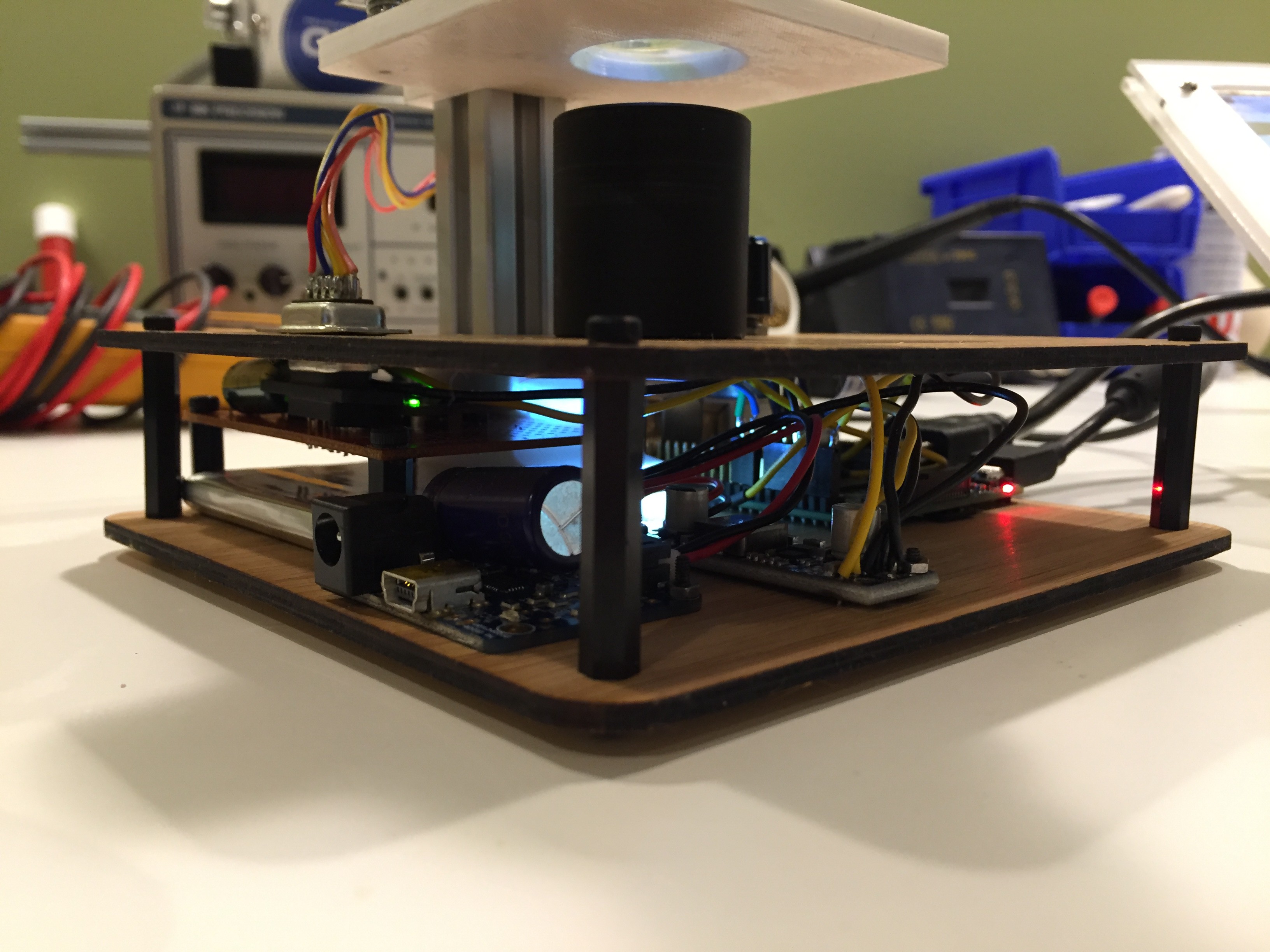
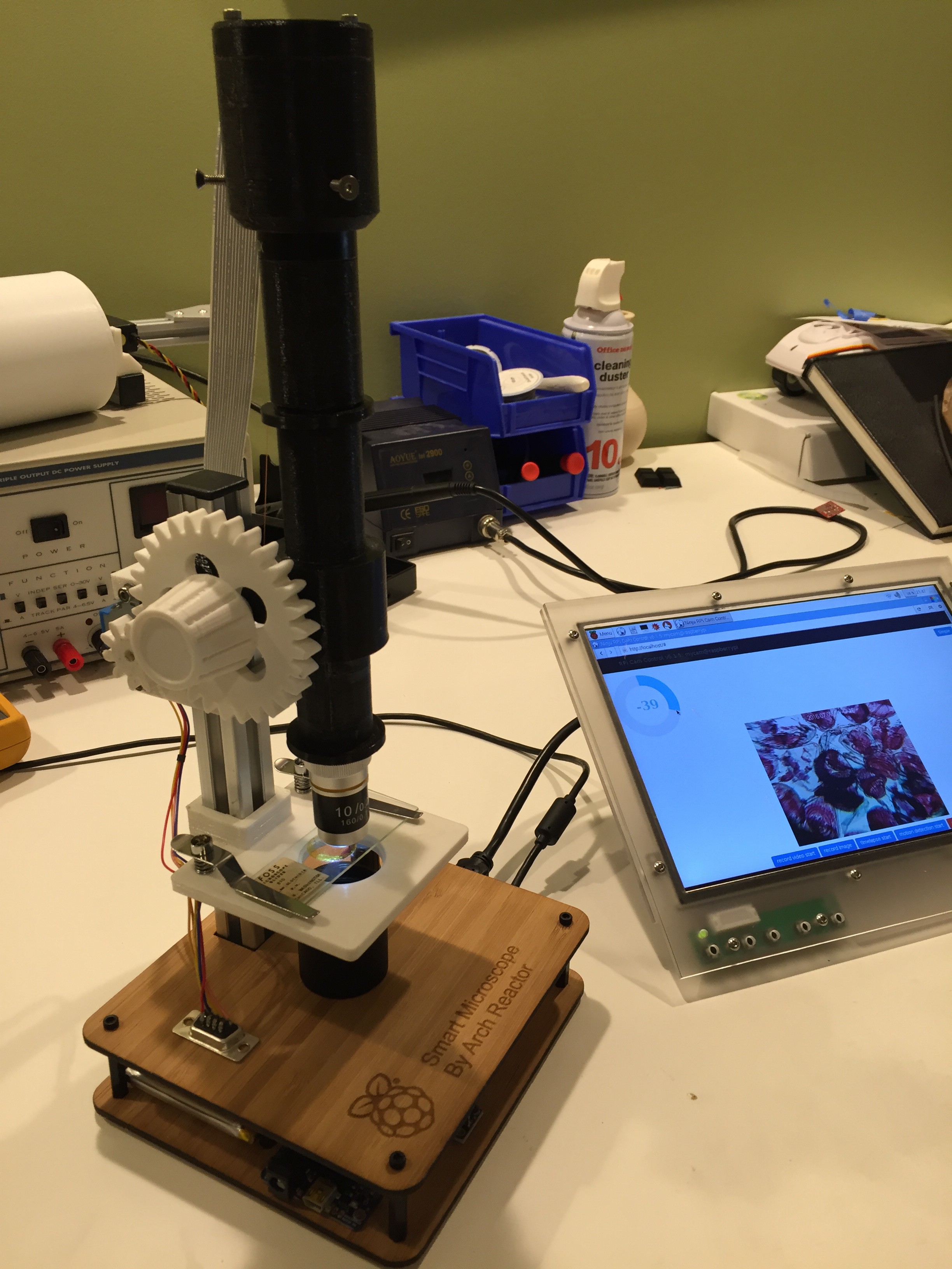 Here is a picture of the final look of the scope with the newly added bamboo base with integrated electronics. I will be adding the files over the next hour or so. This way you can make your own base if you would like.
 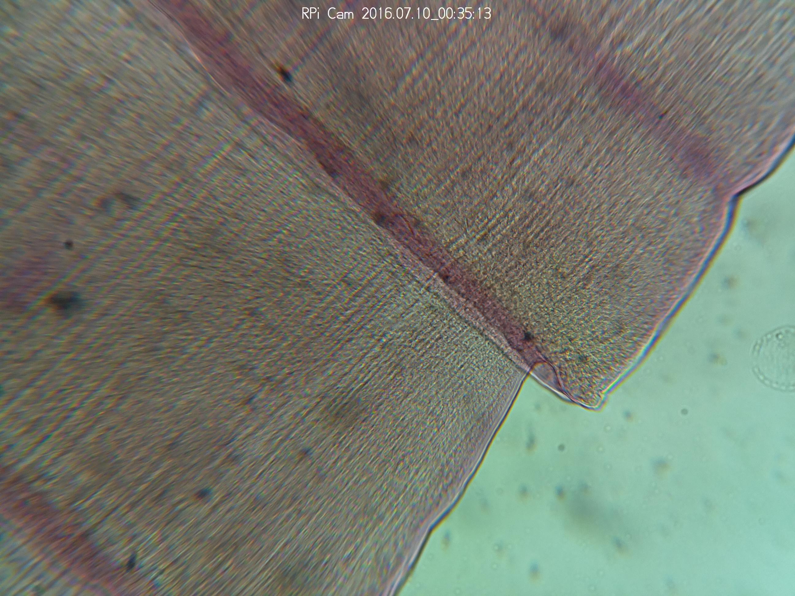 The images are from the updated light and base are looking very clear. Above is a picture of Taenia pisiformis

 Also we we able to get a few more very clear screen shots from the new setup. Below is a pictures of a circuit board and wood fibers