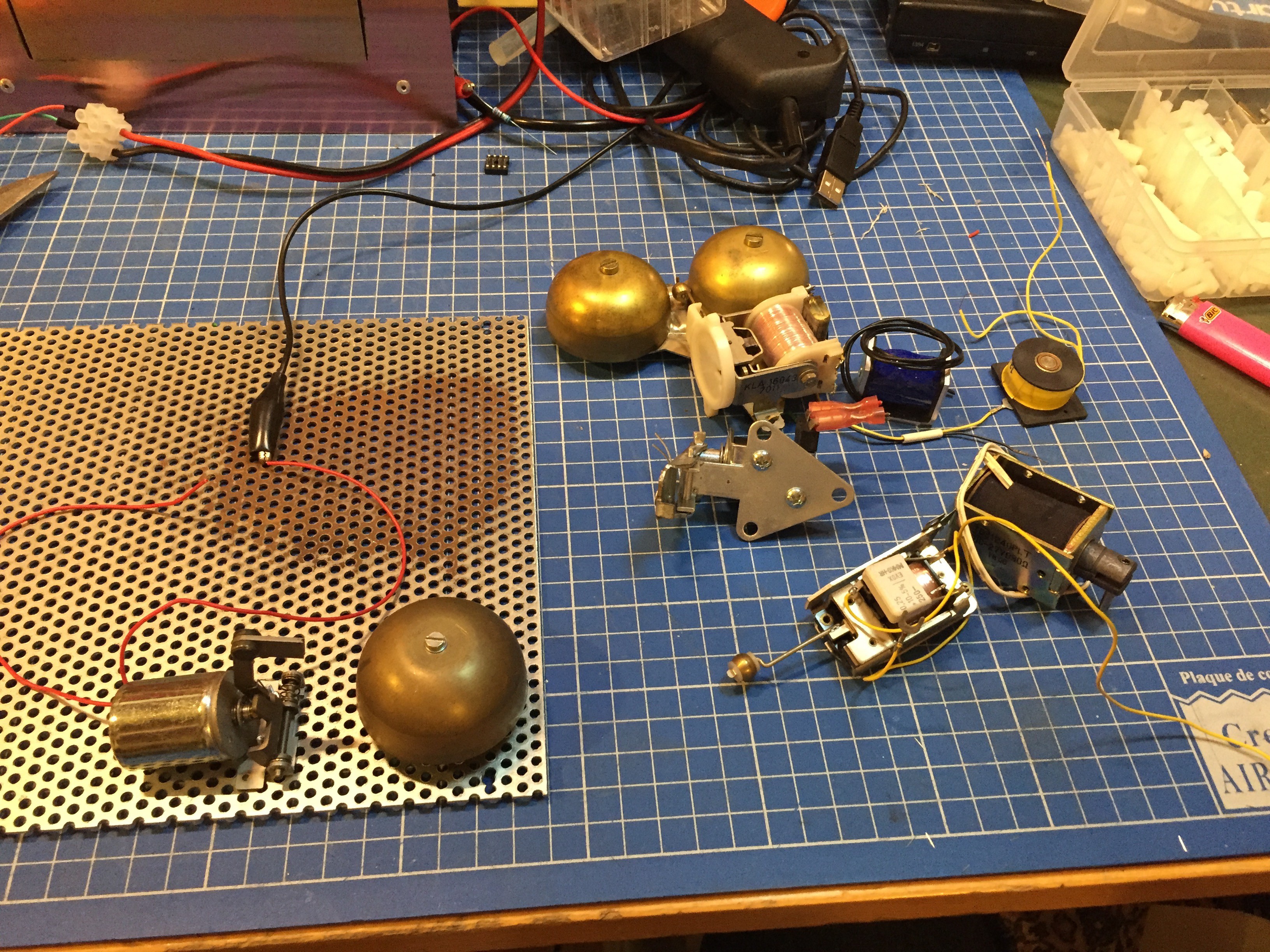
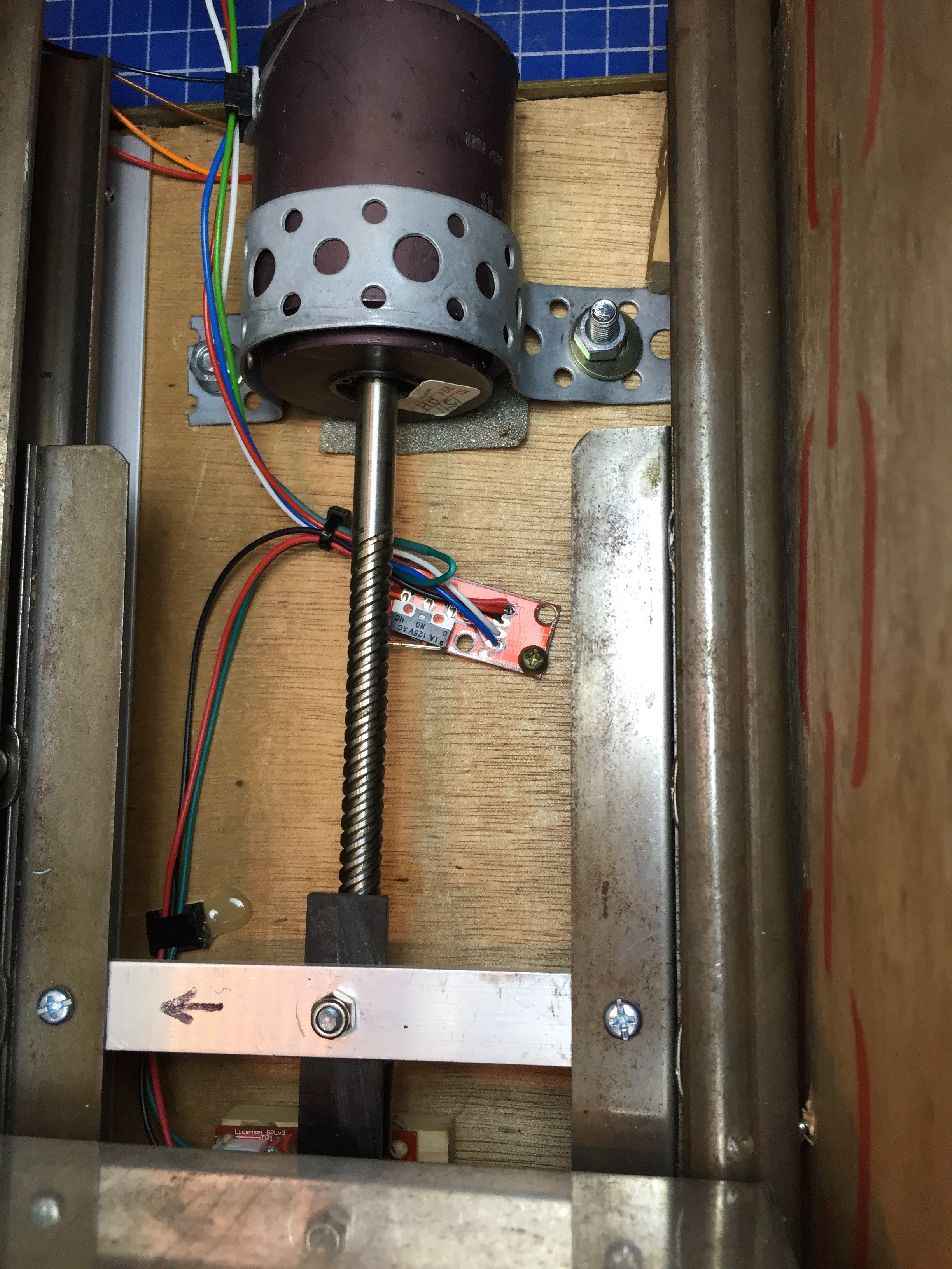
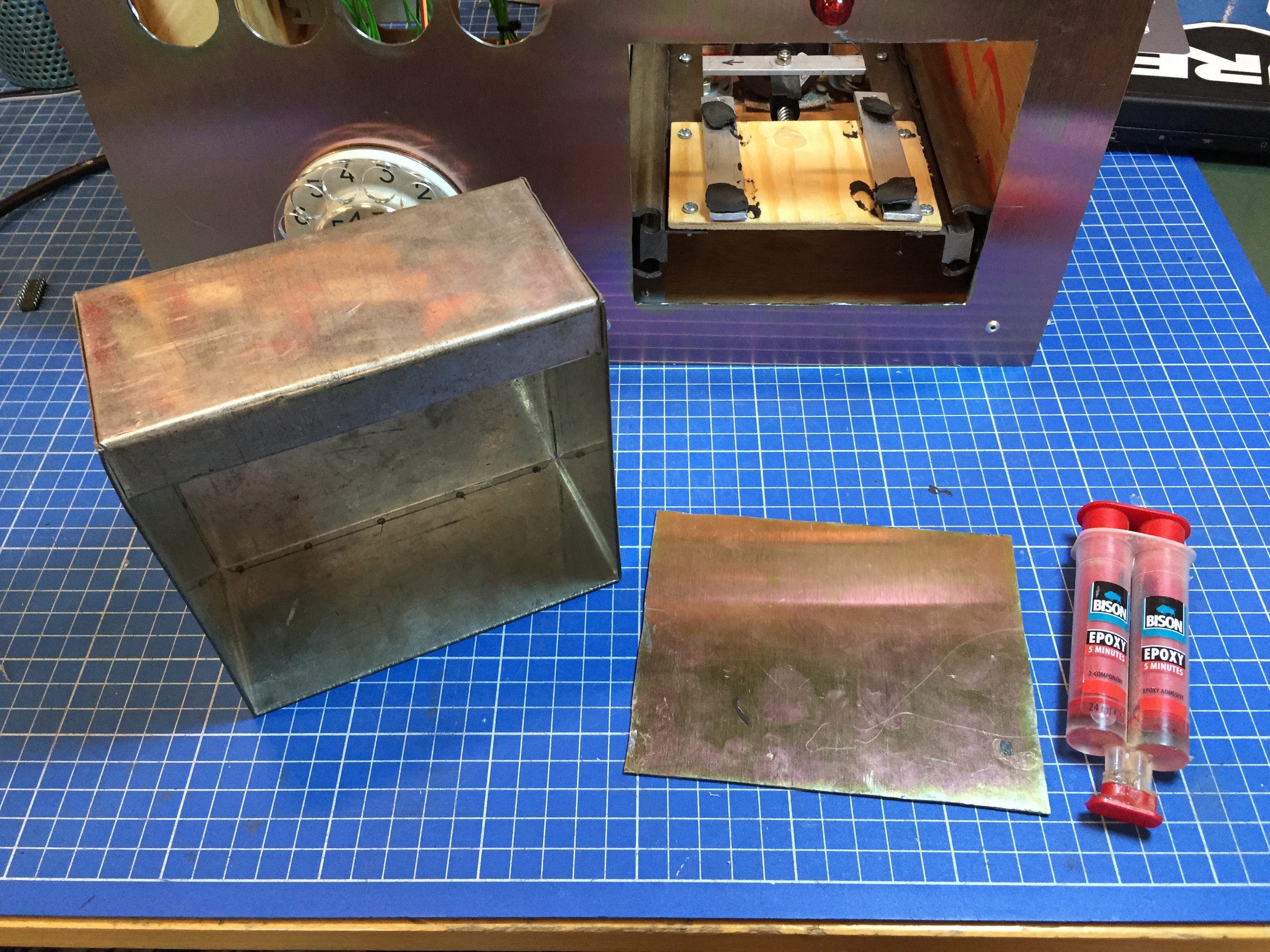
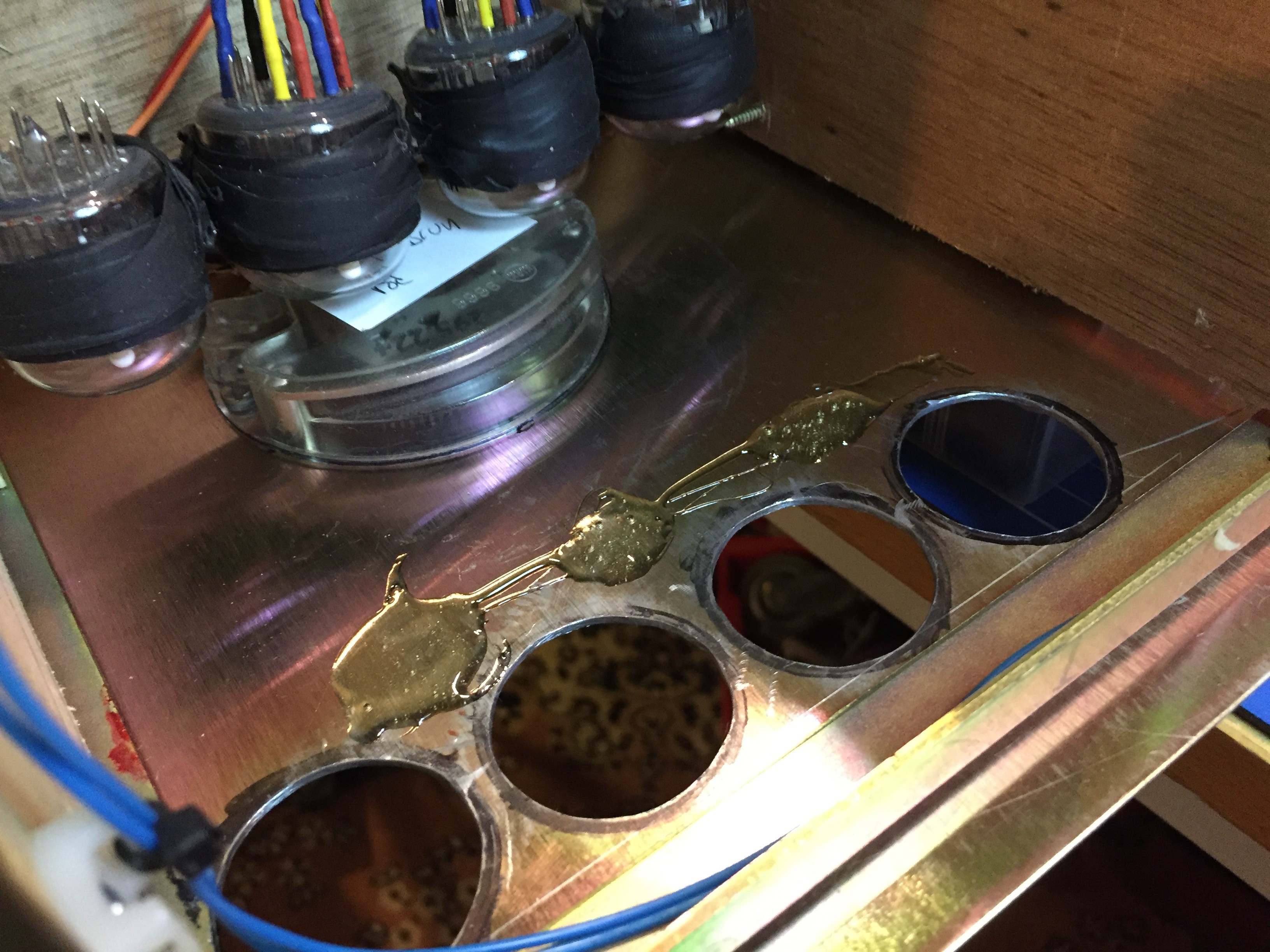
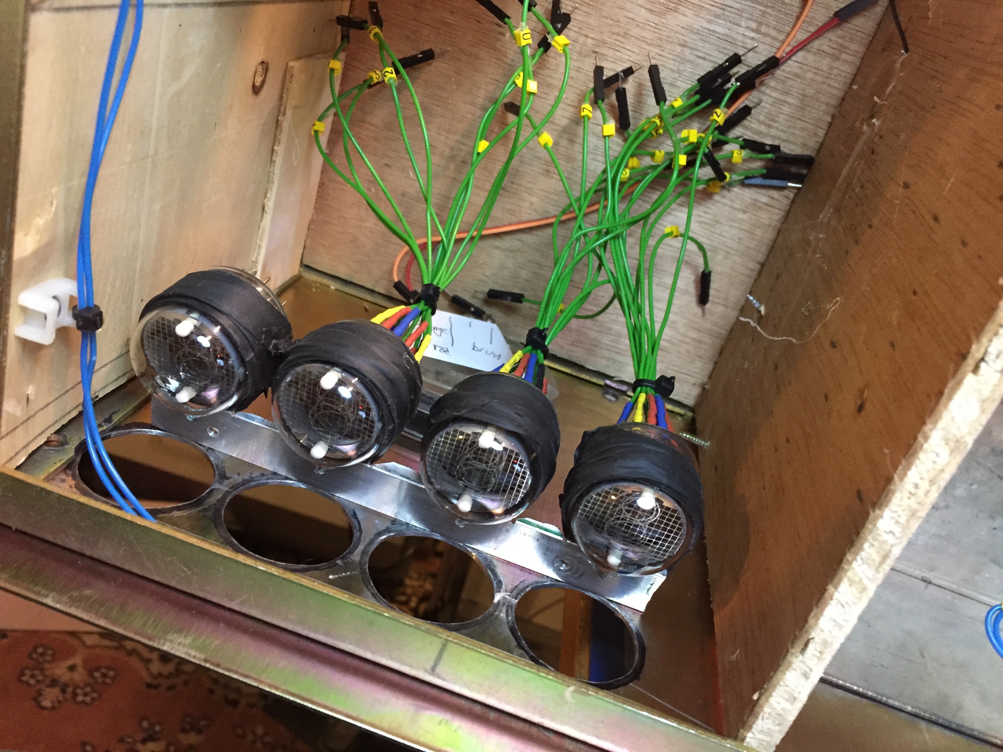
The Idea is to make use of some vintage parts in a fun way. You enter a 4 digit saftey code using the rotary dial, the code is displayed on the four USSR IN-4 nixie tubes as you dial them. And yes I know what you are thinking, it's not a very safe box if a bystander can see whats being dialed, but hey, the reason I'm building a safe is just so that I can use some cool vintage parts in a new way.
Anyway, when the correct code is entered there will be a hatch opening where you can put whatever you want somewhat safe.
Currently working serveral paths:
- Mechanical assembly
- Code
- Nixie driver board + supply (4x K155ID1 + 2 shift registers from the arduino)
- Stepper motor + driver (2 x Darlington arrays)
Firstly I had some trouble with decoding the signal from the rotary dial. It triggered the interrupt function (ISR) in the code in weird ways. The principle behind the rotary dial is that you wind a spring up when you turn the wheel and when you release the spring pulls the dial back. On the way back there is a breaker inside the mechanism that makes a connection everytime you pass a digit. So for example an 8 would be a squarewave-package with 8 falling edges (starting and ending in HIGH, in my case 5v).
As you can see on the picture here the bounce was clear when showed on the scope:
I figured part from the box just opening when you enter the correct code I also wanted some sound. To keep the vintage feel it needed to be a bell of some sort. I had some solenoids and bells from old phones lying around end tried the out.
Since I didn't want to bother with an H-bridge for the phone assembly seen below I combined a loose bell I had with a solenoid that actuates from DC pulses (polarity agnostic) and then springs back. This little contraption (now mounted on a board) also ensures that I get only one singe "bing" wich is what I want. Now I can drive this with one or two channels from the steppers darlington array (I'll have some channels/transistors to spare).
I installed end stoppers for the motor. They are the same kind you would find in a 3D printer (by makerbot), There are two end stoppers, the open position one is barely visible. Here you can also see the stepper motor. It's an old variable reluctance stepper and can therefor be run with a darlington array from 24V.
Once the breakers were in place I glued the plate to the metal box using epoxy.
This is a video of the opening mechanism. The box and all the tubes are temporarily fastened with the black gunk you see around the tubes. It is some sort of industrial blu-tak (very sticky but never solidifies or dries, I got it from a friend working with carbon fiber).
Also here the dial is not connected and I'm manually engaging the opening mechanism. Just to get a sense for how the end result will be. It is very noisy when opening I noticed.
Did some work on getting the IN-4 tubes to glow via two shift registers. After connecting everything I realized I somehow managed to fry 4 of my K155ID1 ICs. It took a while to figure out that they were damaged. I had one left to get the setup running.
Since I don't have the original sockets I've had to make my own, I found a bunch of female connectors that I could solder onto the green wires. I also marked all the numbers. Since I chose not to mount the tubes straight onto a PCB I had a hard time making a holder for them. I eventually settled for vulcanizing rubber and a metal framework.
That was all for today, I did already order new K155ID1:s and while waiting I'll continue on the hardware side.
Мне кажется только русский человек может из старых телефонов собрать сейф :-)