Nyles
Nyles-
Assembly Complete
09/12/2018 at 00:51 • 0 commentsFinally got back to this.

-
Boards, Stencil, Parts, Next
04/20/2018 at 17:16 • 0 commentsThe boards, stencil and parts have all been ordered.
While waiting for materials to arrive, it's time to dig out the CPU development board and start making bits wiggle.
Also need to look into angle sensor hardware and how to bodge that into the dev board.
Cheers,Nyles
-
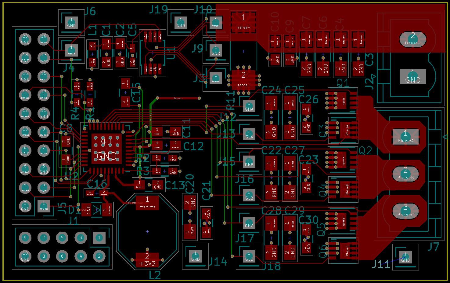
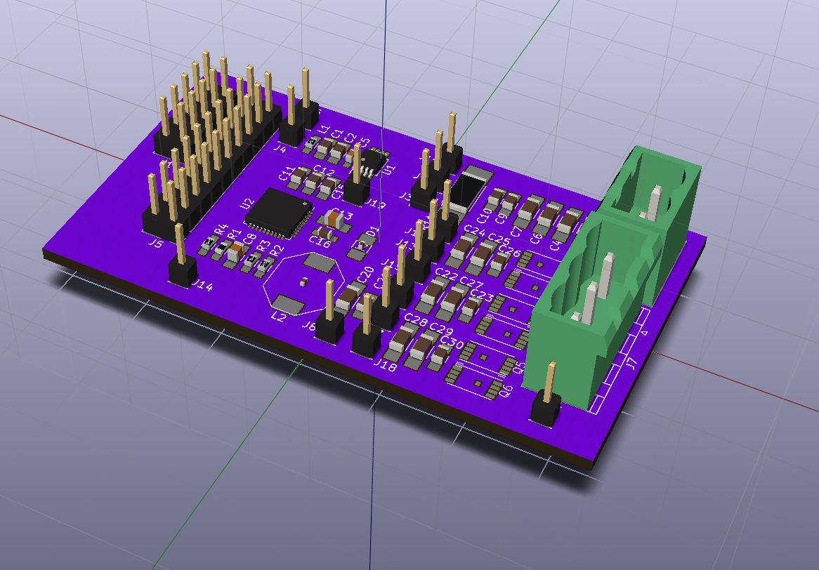
First Layout Complete
04/19/2018 at 20:27 • 0 commentsStarted using zones to pour large copper for the high current areas - after a while it got a bit easier. Not sure KiCad unconnected net tool is too happy about that sort of behavior. :)
The large(ish) inductor is for the builtin buck converter of the phase controller, supplying 3.3V. This will supply power to the CPU in the next revision of the board.
Out to fab is next, as well as ordering the parts.
The latest version of the board design files are in the 'files' section.
Cheers,
Nyles
-
Gear Note
04/13/2018 at 19:46 • 4 commentsI've been trying to find the inspiration for this style of gearbox - I think it was somewhere here on Hackaday, but I can't find it any more. If you check out the Wikipedia article on Epicyclic Gearing, there's a small note on a version of what I'm doing that was done during WWII for the drive box for a portable radar unit. It might not be exactly what I've been doing, which is:
- Start with a normal planetary gear set, with the sun, planets and ring gears.
- Extend the planet gears, and meld in a gear with more teeth. They call this a stepped planet.
- Make a ring gear that mates with the larger gears.
This results, in my current design, in around a 150:1 gear reduction in something a bit larger than my fist. It could be far smaller, but my 3D printer doesn't do well at anything smaller and the amount of output torque scales down as well.
Getting all the gear ratios to match up is a bit of a challenge; not every desired gear ratio is possible. :)
Cheers.
-
Flow Chart in Files
04/13/2018 at 19:22 • 0 commentsOkay, so the email said that I have to put a flow chart up, but doesn't say where to include it, so it's a JPG stuck in the files section. It doesn't really show the scale of the software challenge; I'll be describing this in a bit.
Cheers.
-
First Test PCB
04/13/2018 at 04:01 • 0 commentsAt least a vague approximation - about 2.5" long with a lot of debug headers.
-
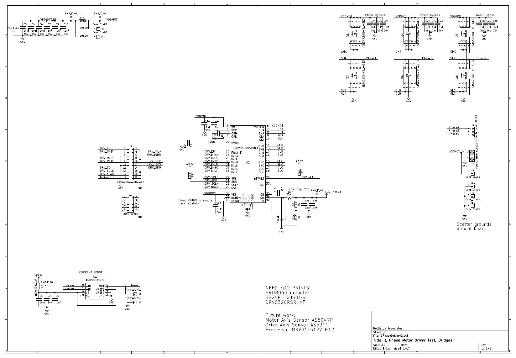
First Schematic
04/13/2018 at 00:51 • 0 commentsI've selected most of what I want to use for the first version of the motor controller. Once the board's out for fab I'll upload the KiCad files. In the meantime here's the working schematic.
It's a JPG, which is not optimal - so if anyone knows how to get a PDF up on one of these log files, please let me know. :)
-
Initial Ramblings
04/02/2018 at 23:42 • 0 commentsSo I've been noodling this sort of idea for a long time now, and I figure that designing an extra large motor controller/gearbox combo for a large hexapod isn't going so fast; maybe a side trip by way of this contest will help me in my eventual developments.
The Servo50 is envisioned as:
- 50 ft-lb target torque
- 120 RPM maximum slew rate
- 12-24V supply
- Brushless motor
- Motor controller with:
- Documentation (KiCAD and source code)
- PWM control
- final drive feedback with index
- motor axis feedback for good commutation behavior
- Planetary or epicyclic gearbox
I have a few good 'from scratch' gearboxes that I've designed and fabricated. The electronics are inspired by the ODrive project, however the board for the Servo50 will only control one motor.
That's it for now, time to start on that motor controller.
Cheers,
Nyles
Servo50: Scaling Servo-Based Projects
There seems to be an empty spot in the market between hobby servos and professional models - this should partially fill that gap.