Boards are available
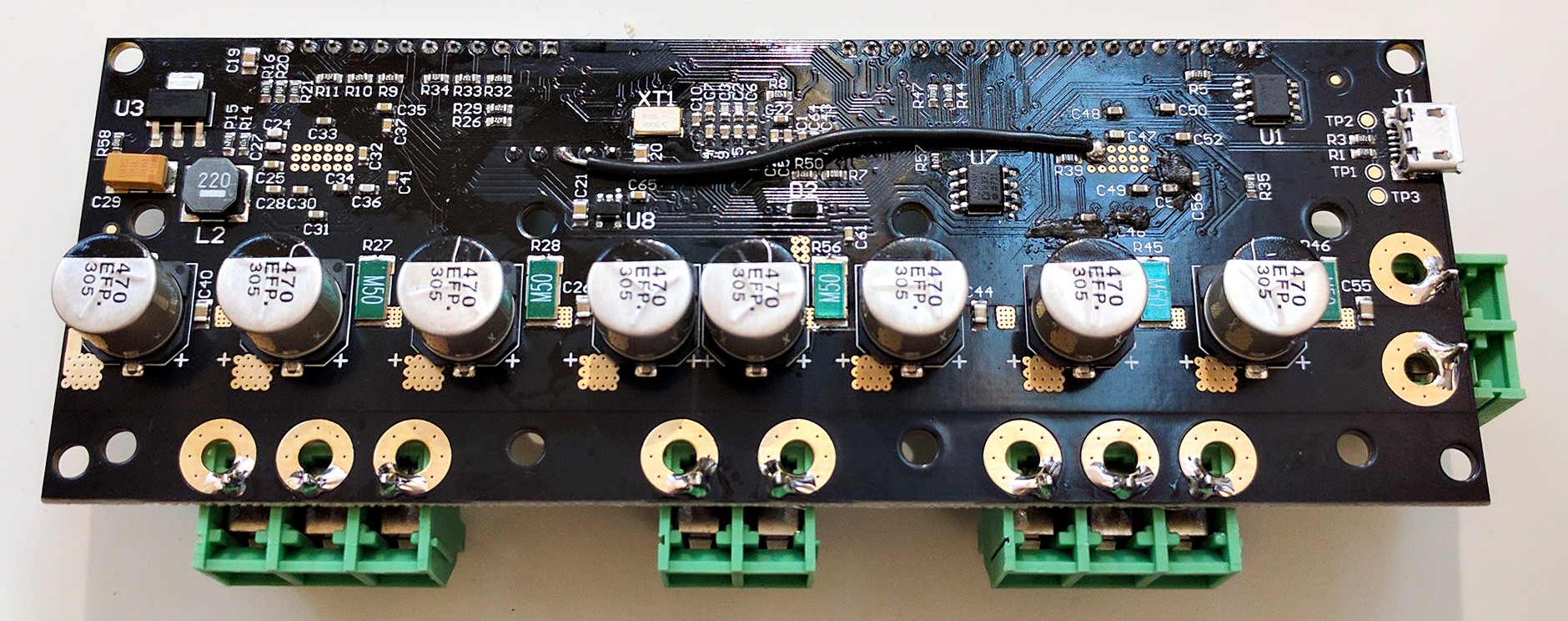
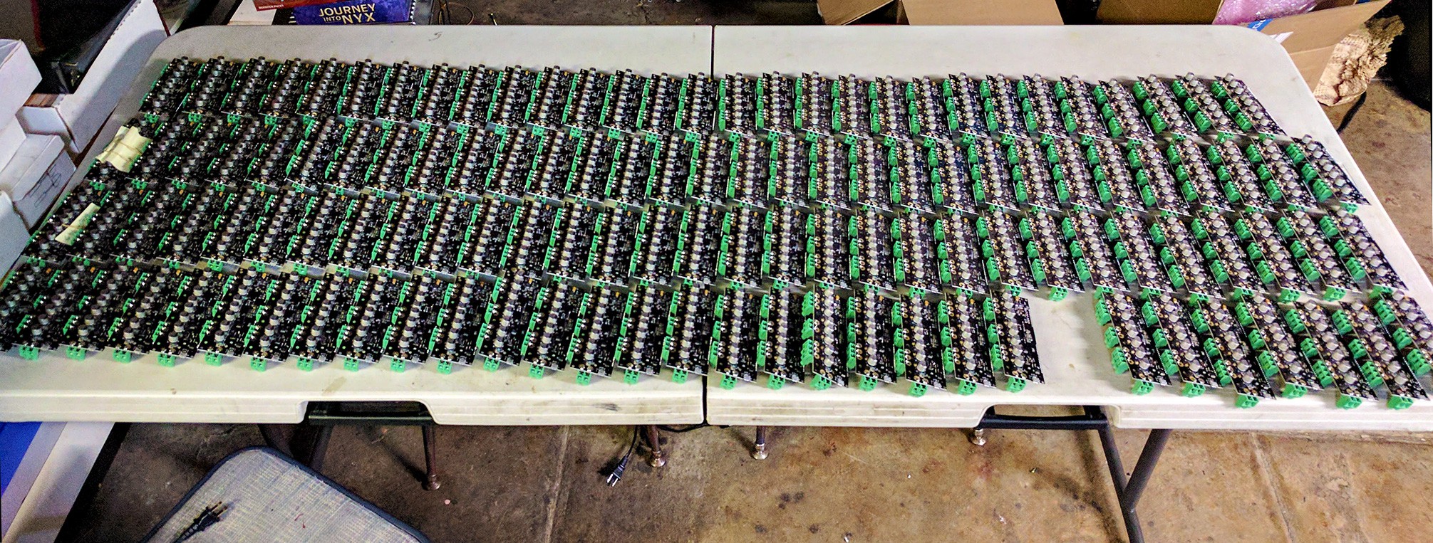
ODrive v3.5 boards are available at the ODrive Shop.
Key specs:
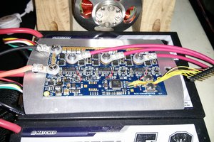
- 2 motor channels, designed for >100A peak current.
- 1 DC-DC converter channel
- For powering the system with an arbitrary voltage power supply, or
- Use of a brake resistor
- 24V bus voltage
- USB, CAN, UART, PWM, and step/dir interface (read more below)
- Encoder feedback for arbitrarily precise movements
- Supports power regeneration
- Use of a high power density Li-Po battery means you can achieve >1kW peak power output with only a modest power supply.
- It will feature various optimal control strategies and motion profiles.
- Permissive licence on both hardware and software: You use this project in anything you like, even commercial products (as long as you attribute this project's contributors).
Demos
The design is based on two earlier prototypes.
Here are some very simple demos with v2. The peak power output in these tests were only about 60W. The new version (v3) will be able to deliver much more power.
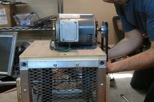
Below is a demo with v1. The mass being moved is 3kg, and the peak power was about 200W. The noise is not from the motor, but from my poor mechanical design which means that the belt teeth rubs against the idler pulley edge.
Join the discussion!
Check out the ODrive Community.
Stay up to date
- Sign up to the ODrive Newsletter
- Follow on Twitter or Facebook
Motors
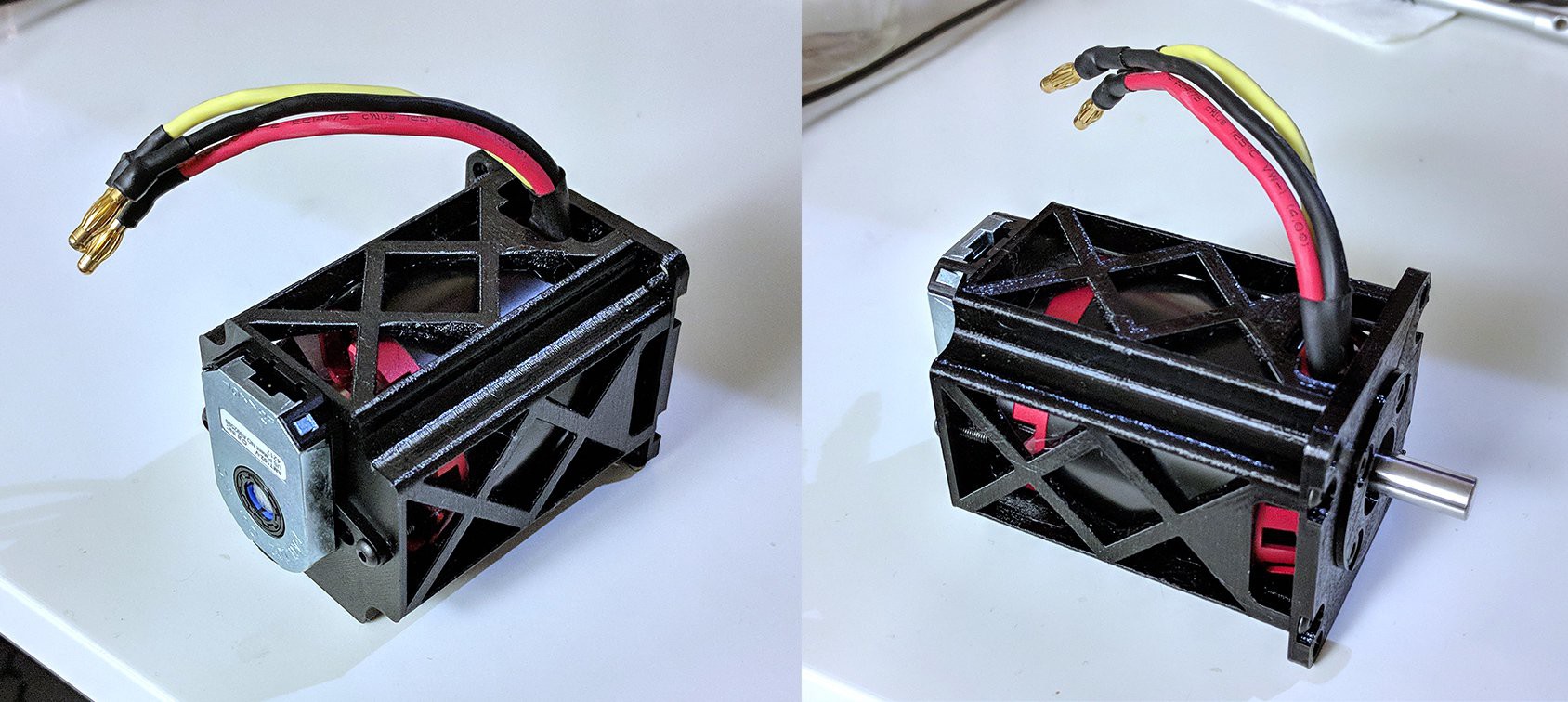
Check out the ODrive motor guide. You can also read this post about outrunner motors.
Interfaces
- USB Serial port -- PC, BeagleBone, RaspberryPi, etc.
- CAN -- CANOpen and CiA 402 is a possibility
- UART -- Arduino, mBed, etc.
- PWM -- RC Recievers, Arduino, etc.
- Step/direction -- Existing motion controllers
- Some general purpose digital and analogue pins
Protocols
- G-code parser for interfacing with existing automation tools
- Many types of command modes
- Goto (position control with trajectory planning)
- Position commands
- Velocity command
- Torque command
Architecture
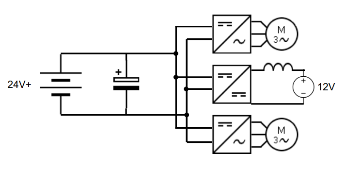
The drive is designed to be able to deliver incredibly high peak power, more than 1kW per motor channel. However, power supplies that can deliver this kind of power are expensive. Also, when the actuator is being decelerated, there is energy absorbed. Most power supplies do not like having energy dumped back into them.
The solution: Put high-power energy-storage on the DC bus. A battery like this one can deliver around 3kW. These types of batteries also have a fairly high charge rating, and if the regeneration is only over a couple of 100 milliseconds, they can probably handle a fair bit more than specified. Thus, they should be able to handle the full range of regeneration power in most robotics applications.
This means we have a variable voltage DC bus, that fluctuates with the battery's state of charge. So the way we power the system is via a DC-DC converter. There is another upside to this as well: we can use any voltage power supply and just convert it to the bus voltage. I expect most people will use an inexpensive ATX power supply (specifically the 12V rails). In many robotics applications the motion consists of several discrete movements, only some of which are high power. In this case, we can have access to a very high peak power, but only require a very modest power supply.
Another thing that's nice about using a battery for stabilising the DC bus, is that if multiple of these drives reside on the same bus, there is no fighting over the regulation of the bus voltage: a single board can have the DC-DC connected to a PSU, and the rest of the boards in the system can just use the bus. If fact, you can even skip populating the DC-DC on the slave boards.
The system is also capable of using a brake resistor to dump the regenerated energy instead of a battery to absorb it. This is a simpler and possibly safer setup, and is also what the project will use in the first instance, until the battery storage feature is ready.
Applications
So this project is good for some things,...
Read more » Oskar Weigl






 Jarrod
 Scott Swaaley
Please don't use CircuitMaker, us Linux people are excluded. :( This project is amazing!