-
Ready for Launch
06/23/2014 at 23:10 • 2 commentsUpon the completion of the thrust vectoring chassis, I made a body out of thin wall fiberglass. This rocket has no fins due because the test code pasted in the description will make the rocket self stabilize, if the rocket stays pointed up during the flight, we will know that our thrust vectoring system works.
![]()
-
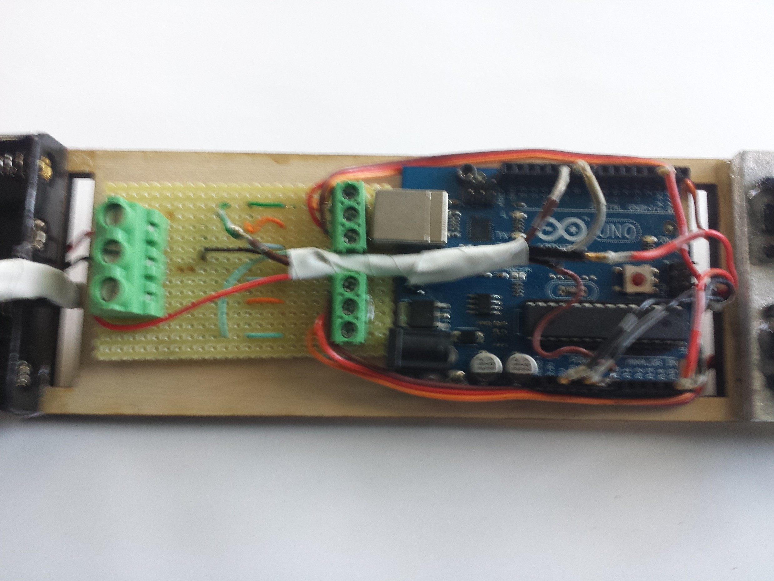
All Components Attached
06/20/2014 at 20:50 • 0 commentsAs each piece of the electronics were tested individually, it was finally time to mount everything in the electronics bay. The IMU was mounted in the front so that it picks up even the smallest changes in rocket orientation. The rocket electronics went from this:
To This:
![]()
-
The Electronics
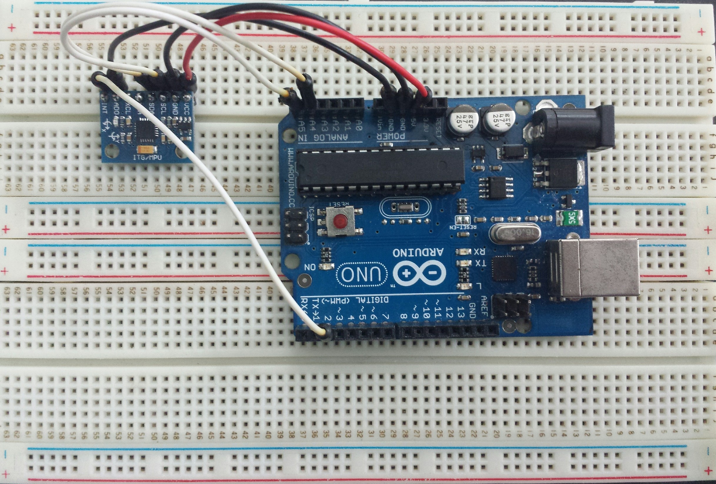
06/20/2014 at 20:46 • 0 commentsI finally got out of the prototyping stage and all the ordered electronics work how they are intended! Now comes the hard task of fitting everything on the electronics bay so that it wont come loose with vibration. To do this, a custom cable was made for the IMU, a sensor which will tell the arduino what orientation its facing.
![]()
Along with this, a power control circuit was designed and made using PCB, it was planned to make an all in one rocket control board, but this turned out to be more simple for prototyping. The power control board takes 11 volts from a LiPo battery pack and distributes it to the IMU, the Arduino, and the two servos while keeping everything cool and safe from coming loose
![]() The servos connect to the screw terminals on the left hand side, while the batter goes on the bigger terminal, the 3 wires connect to arduino and are (ground, PWN9, and PWN10)
The servos connect to the screw terminals on the left hand side, while the batter goes on the bigger terminal, the 3 wires connect to arduino and are (ground, PWN9, and PWN10) -
Lasercut Aluminum Frame!
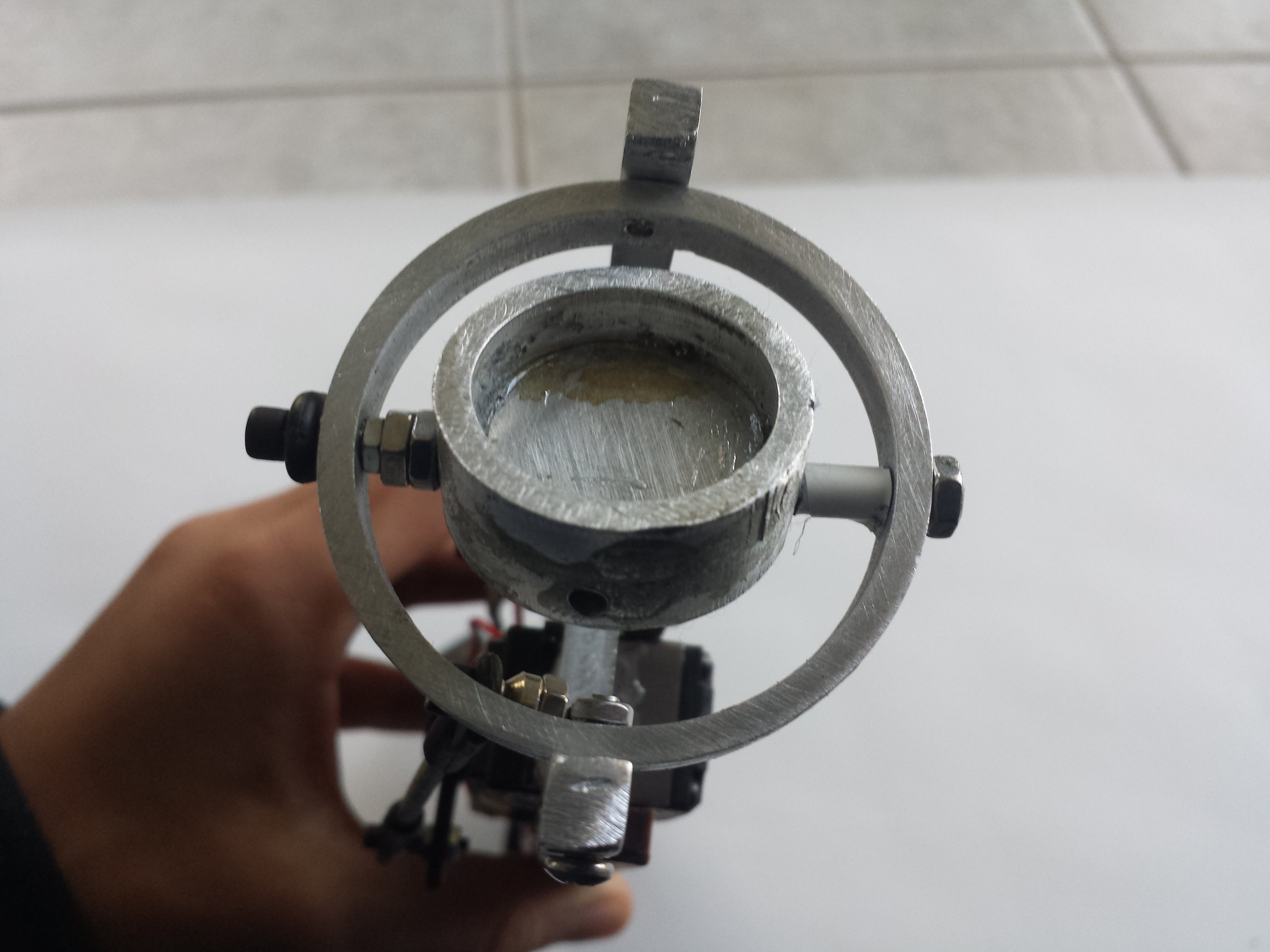
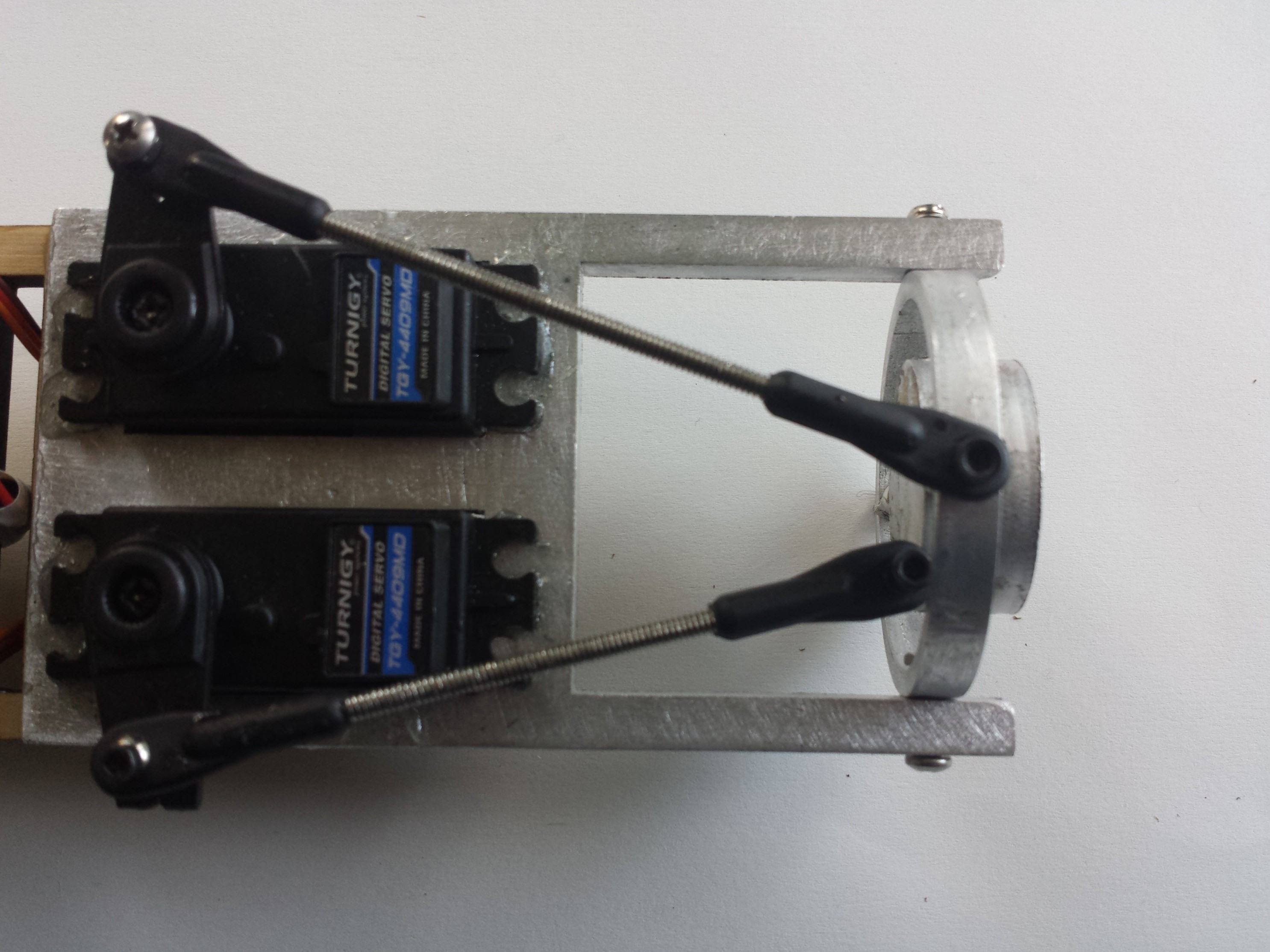
06/20/2014 at 20:40 • 0 commentsAfter the failure of the wood frame, a local machine shop made me a .25 inch thick aluminum frame! This frame was later tapped and threaded by me so that the gimbal can fit in it. After the parts were fitted, red permanent locktite was used to make sure they never come off during flight. Along with this, a plywood electronics bay was also laser cut.
![]()
![]()
-
Thrust Vectoring Frame
05/18/2014 at 15:33 • 1 commentAfter doing a static test on the laser cut plywood frame, it was discovered the the wood grain greatly weakens the wood and results in catastrophic failure. In order to fix this, I will be moving on to a better material such as aircraft grade aluminum, which is more heat resistant and stronger. The aluminum will be .25 inches thick and will be laser cut by a local machine shop. In order to conponsate for the heavier frame, a higher impluse motor will have to be used.
Guided Rocket
I will be attempting to build a guided rocket using of the shelf parts
 Sagar
Sagar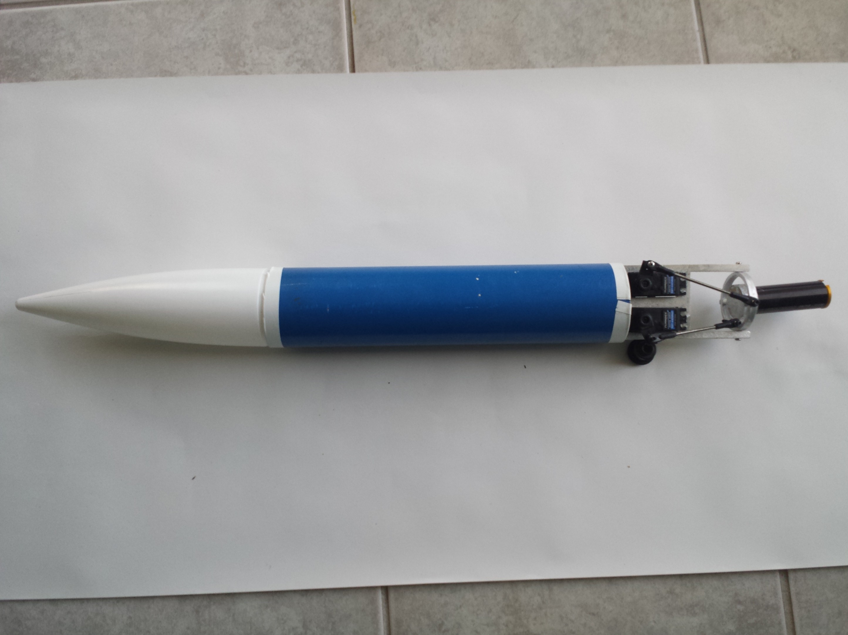

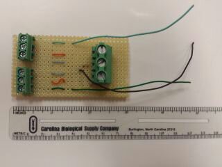 The servos connect to the screw terminals on the left hand side, while the batter goes on the bigger terminal, the 3 wires connect to arduino and are (ground, PWN9, and PWN10)