Mike Rigsby
-
Conveyor Belt
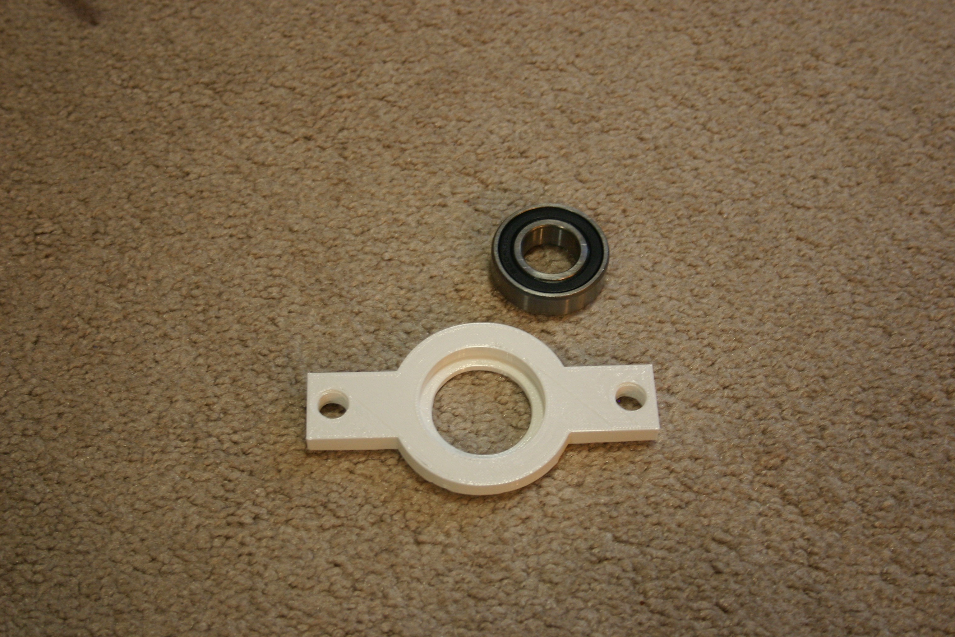
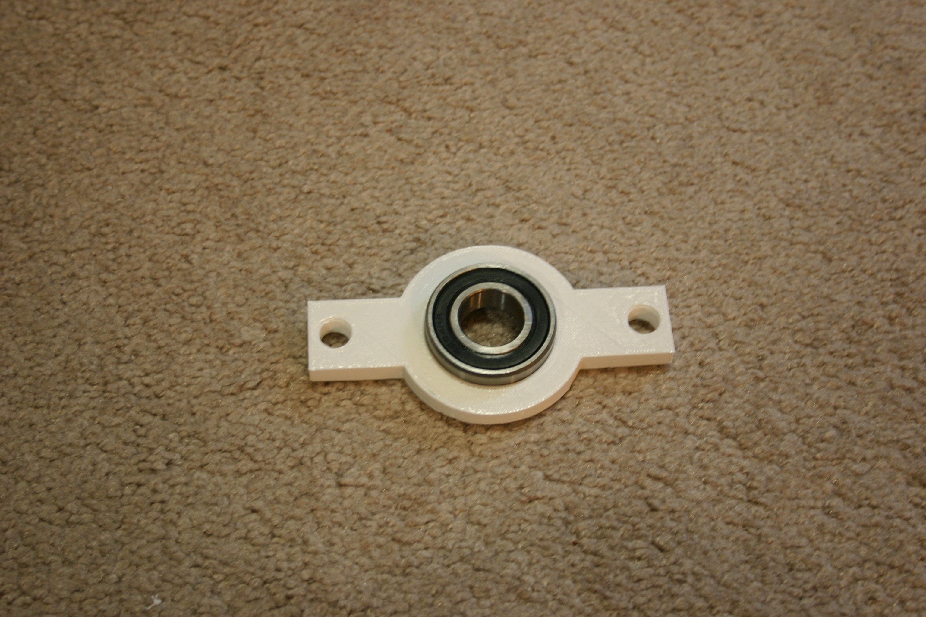
04/20/2018 at 19:04 • 0 commentsPrint (3) bearing supports and install 6x19x6 mm bearings.
![]()
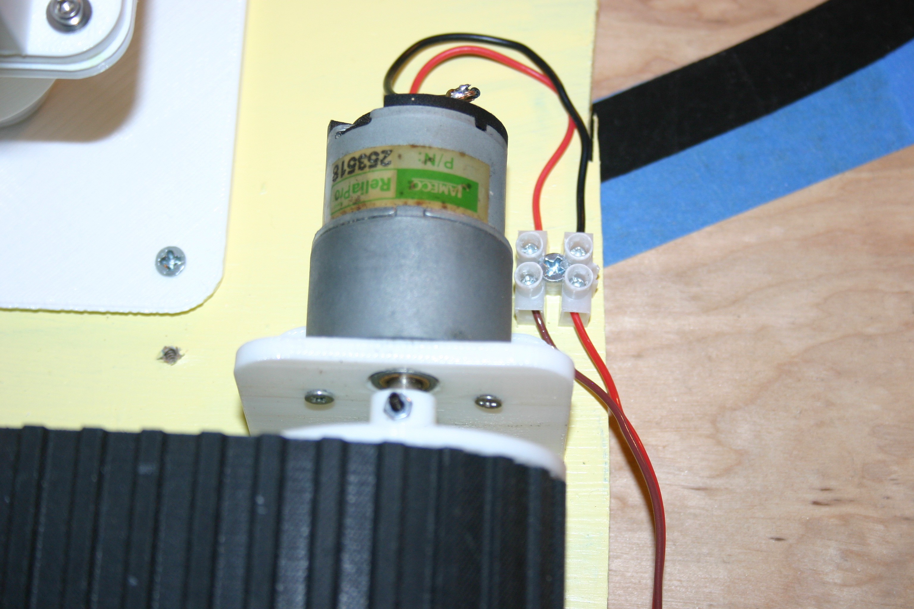
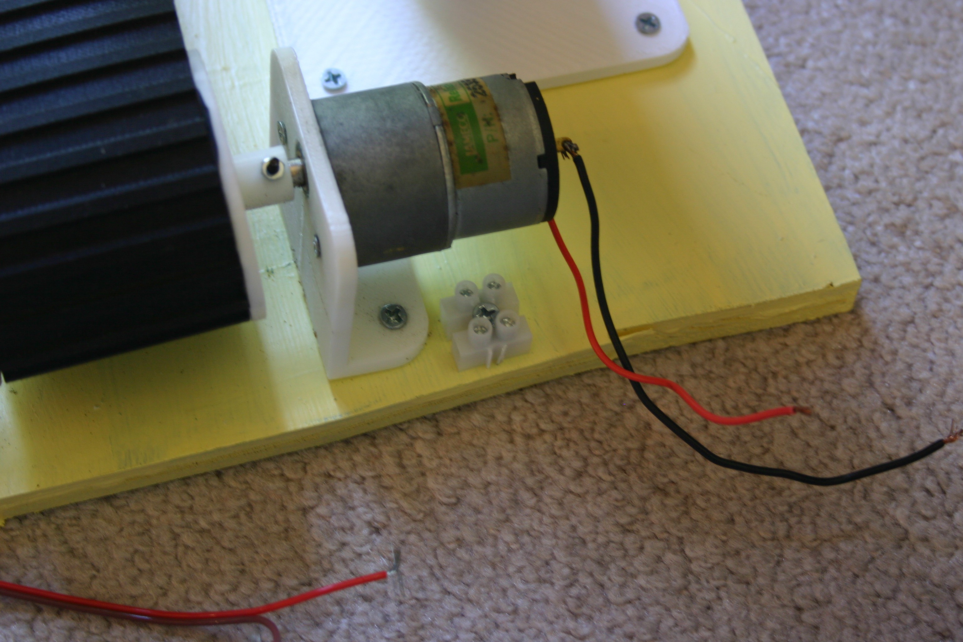
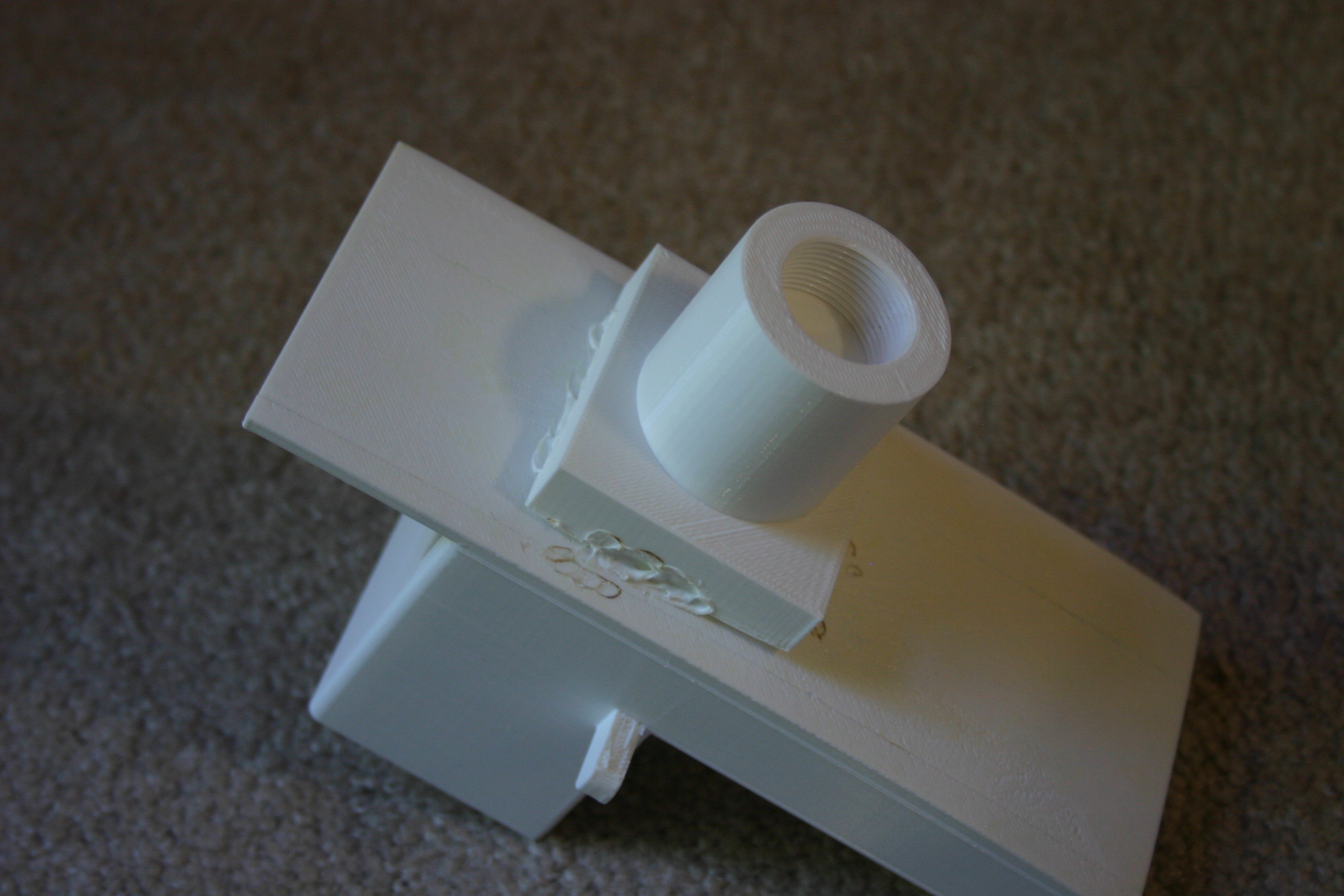
Print one "belt spool motor" and one "belt motor bearing." Glue or melt the "belt motor bearing" to the end of the "belt spool motor."
![]()
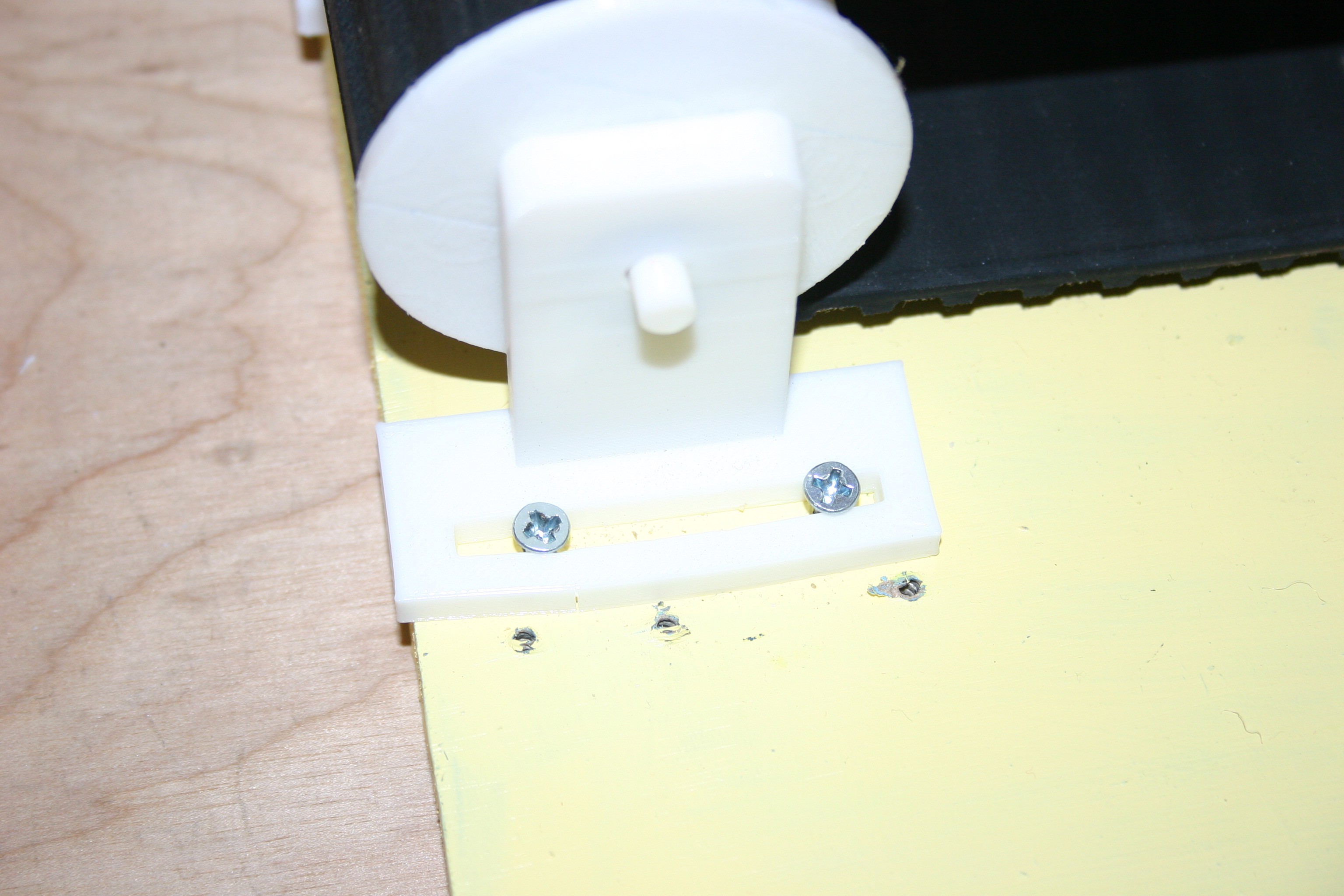
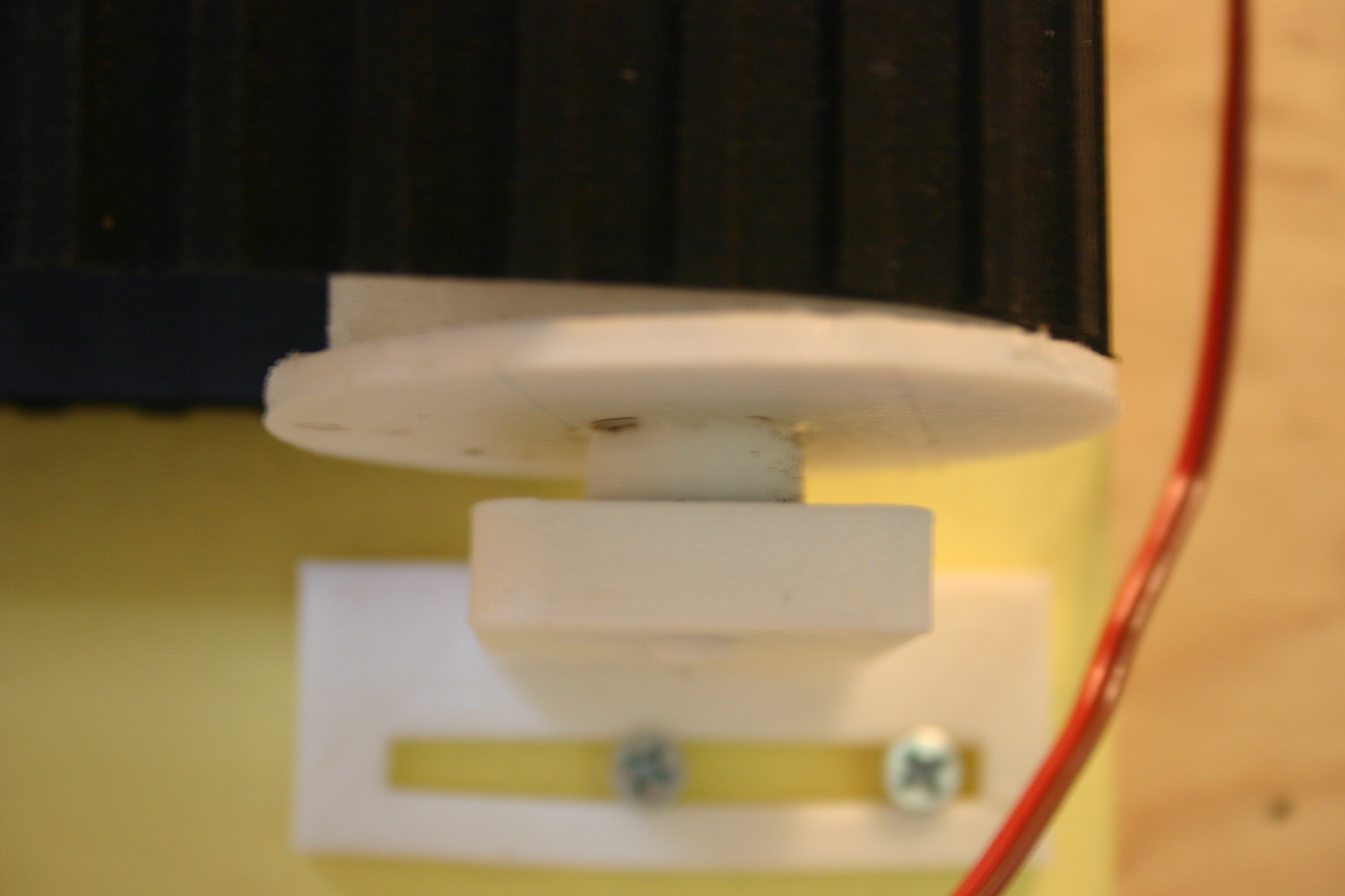
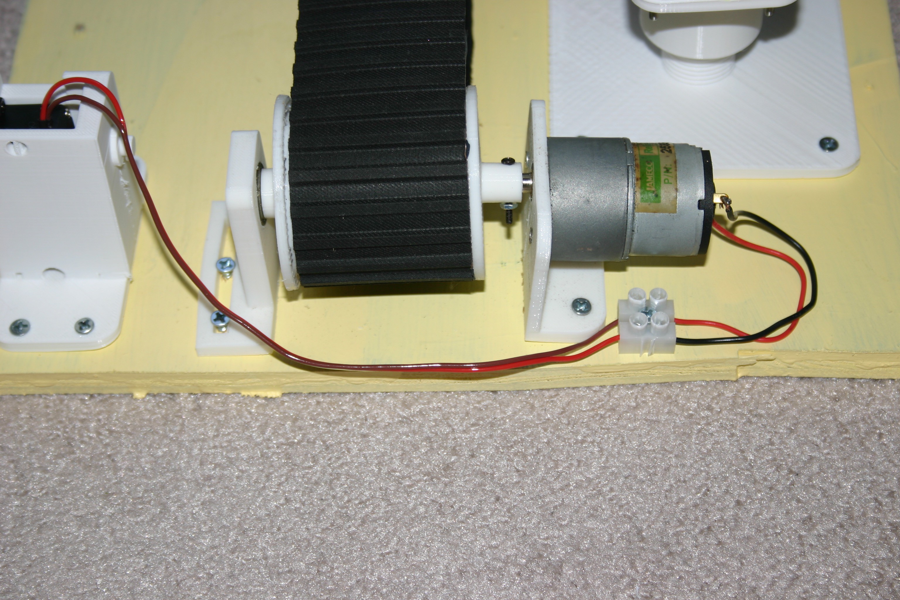
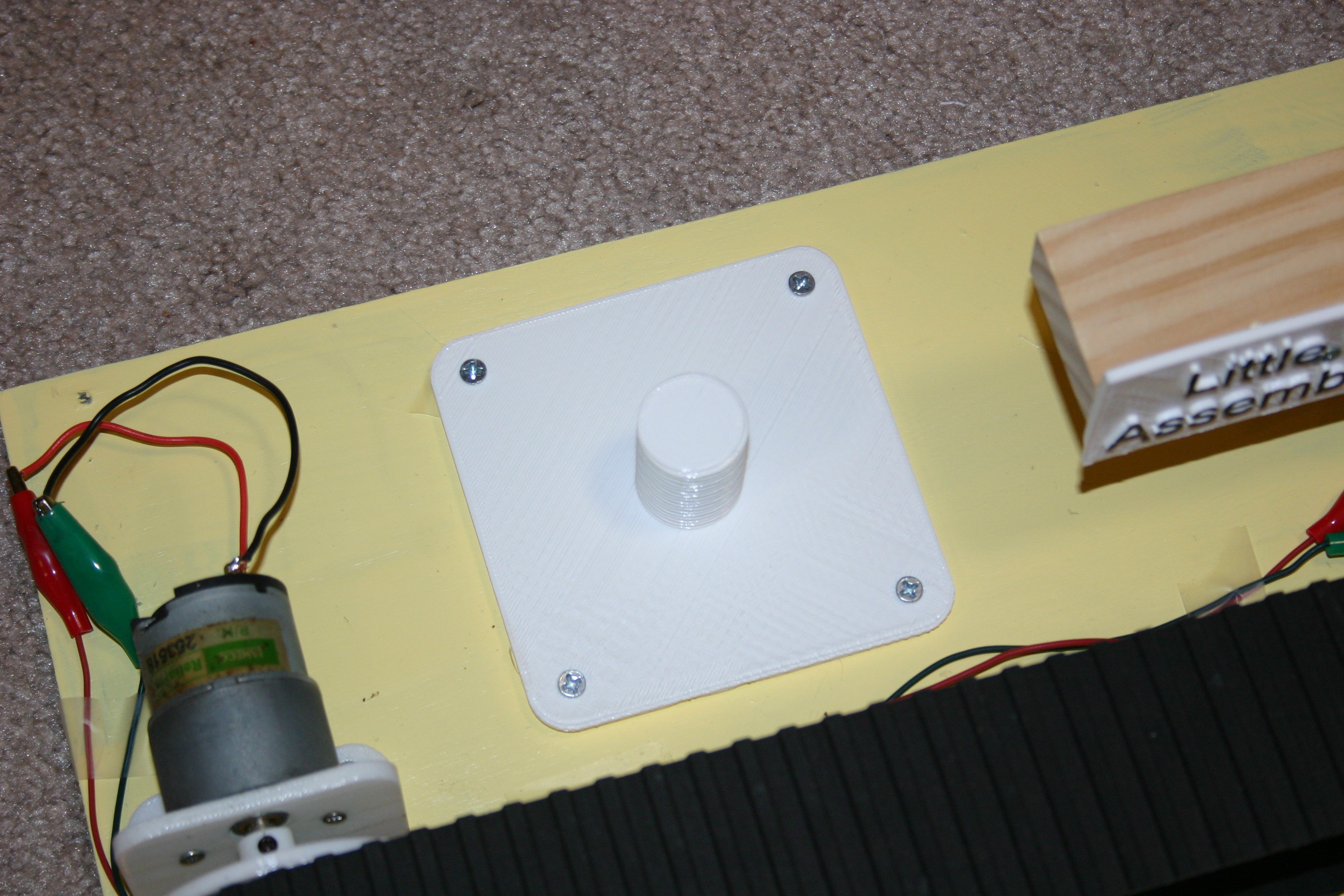
Print one "belt spool" and two "belt motor bearing" pieces. Glue or melt the "belt motor bearing" pieces to the ends of the "belt spool." Wrap the belt around the spools, then place the shaft ends into the "bearing supports." Place the motor in the "motor holder" (secure with 3mm screws). Adjust the bearing supports until the belt is in reasonable tension, then secure to the plywood base using wood screws.
![]()
-
Generator
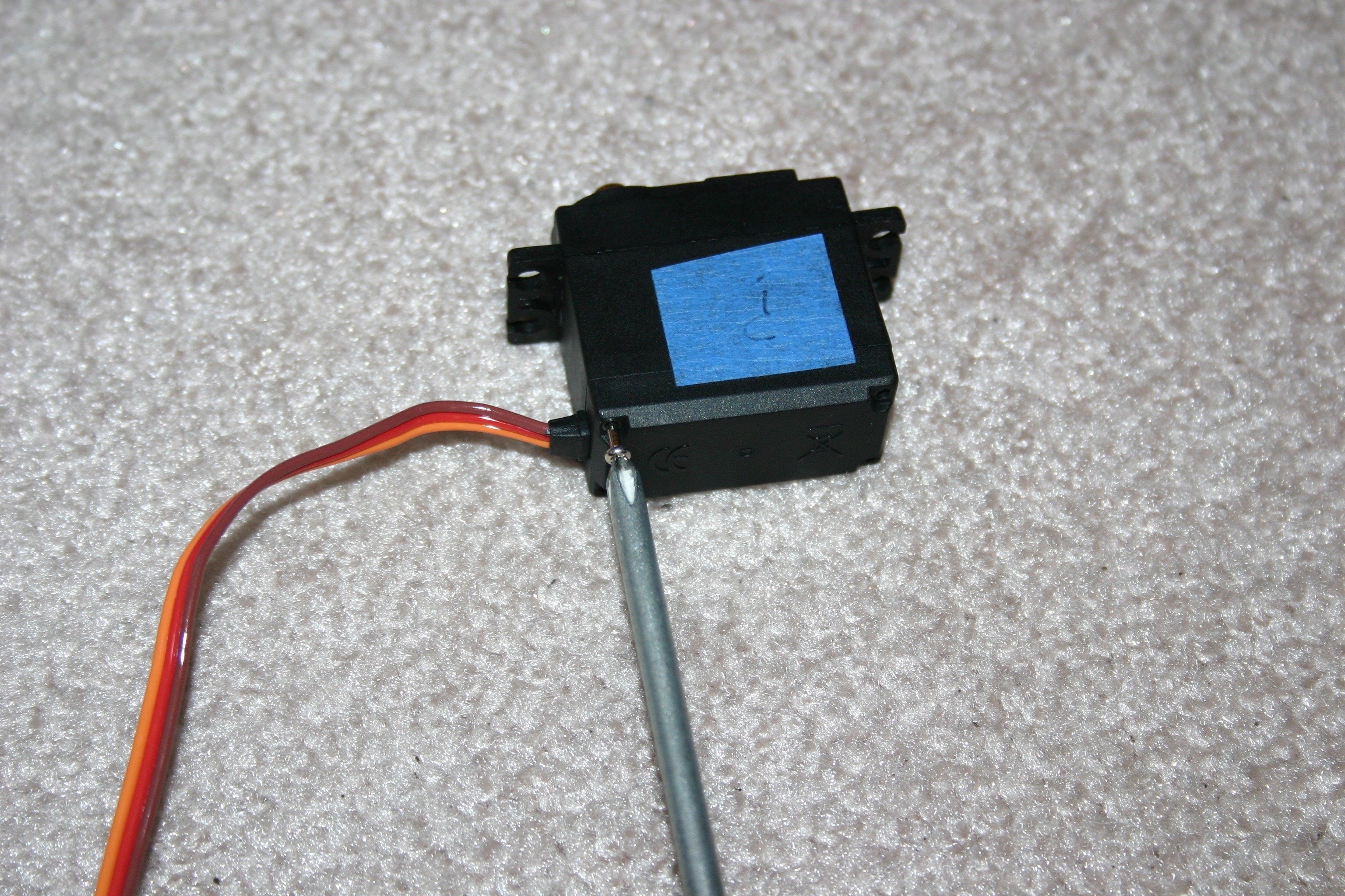
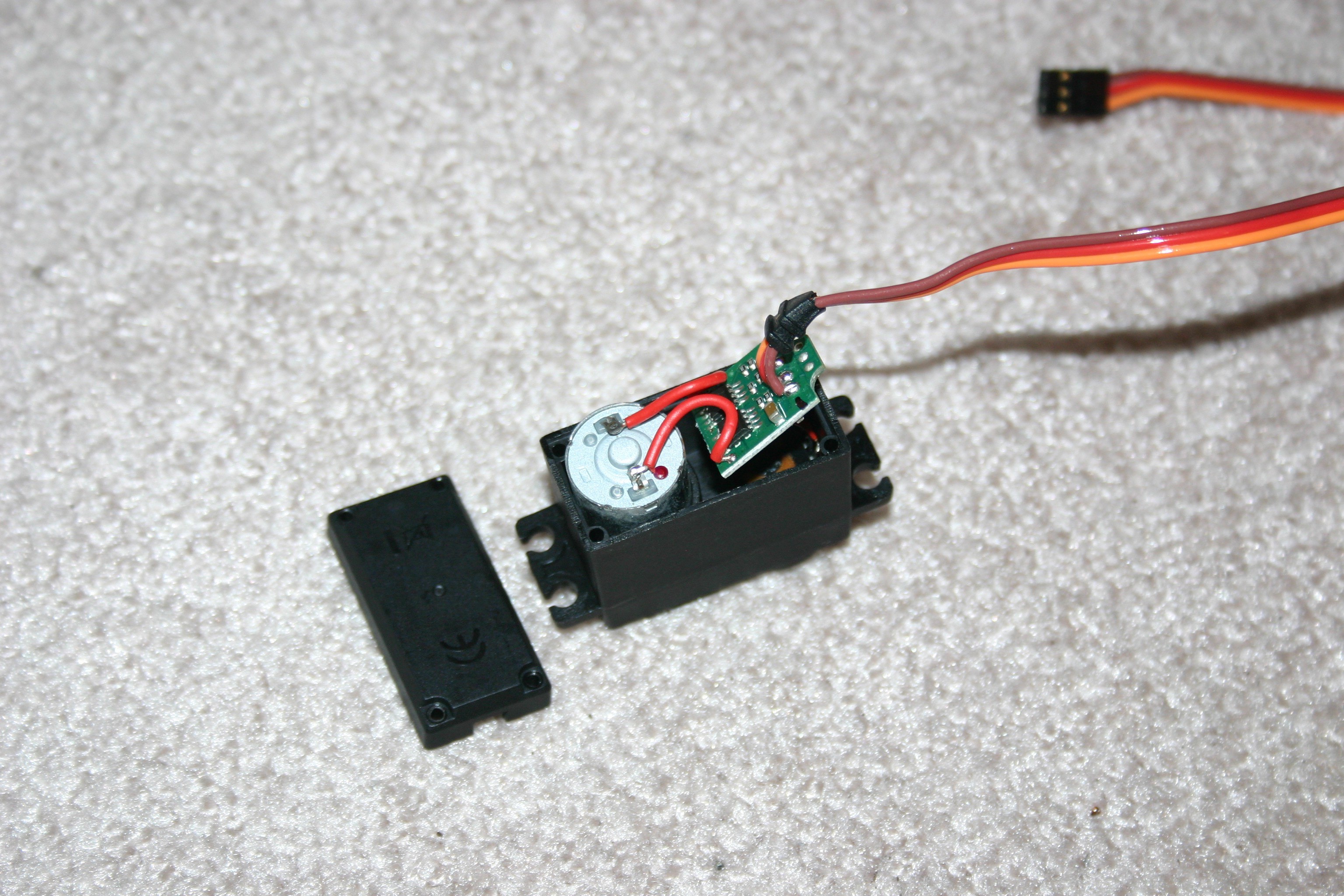
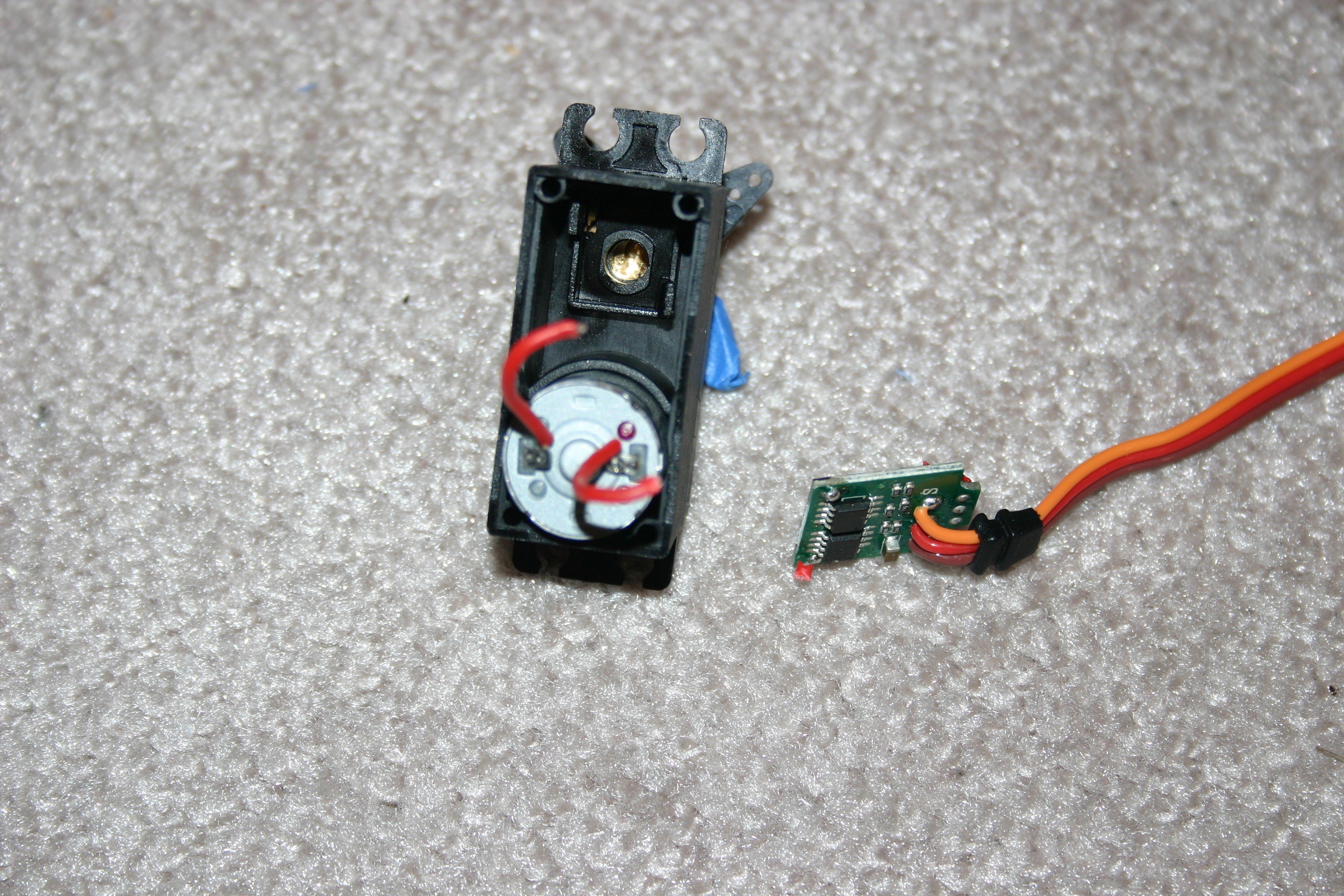
04/20/2018 at 17:16 • 0 commentsIn this step I create a hand crank generator to power the conveyor belt. Let's start with a MG995 servo motor.
![]()
Remove the screws and the back plate.
![]()
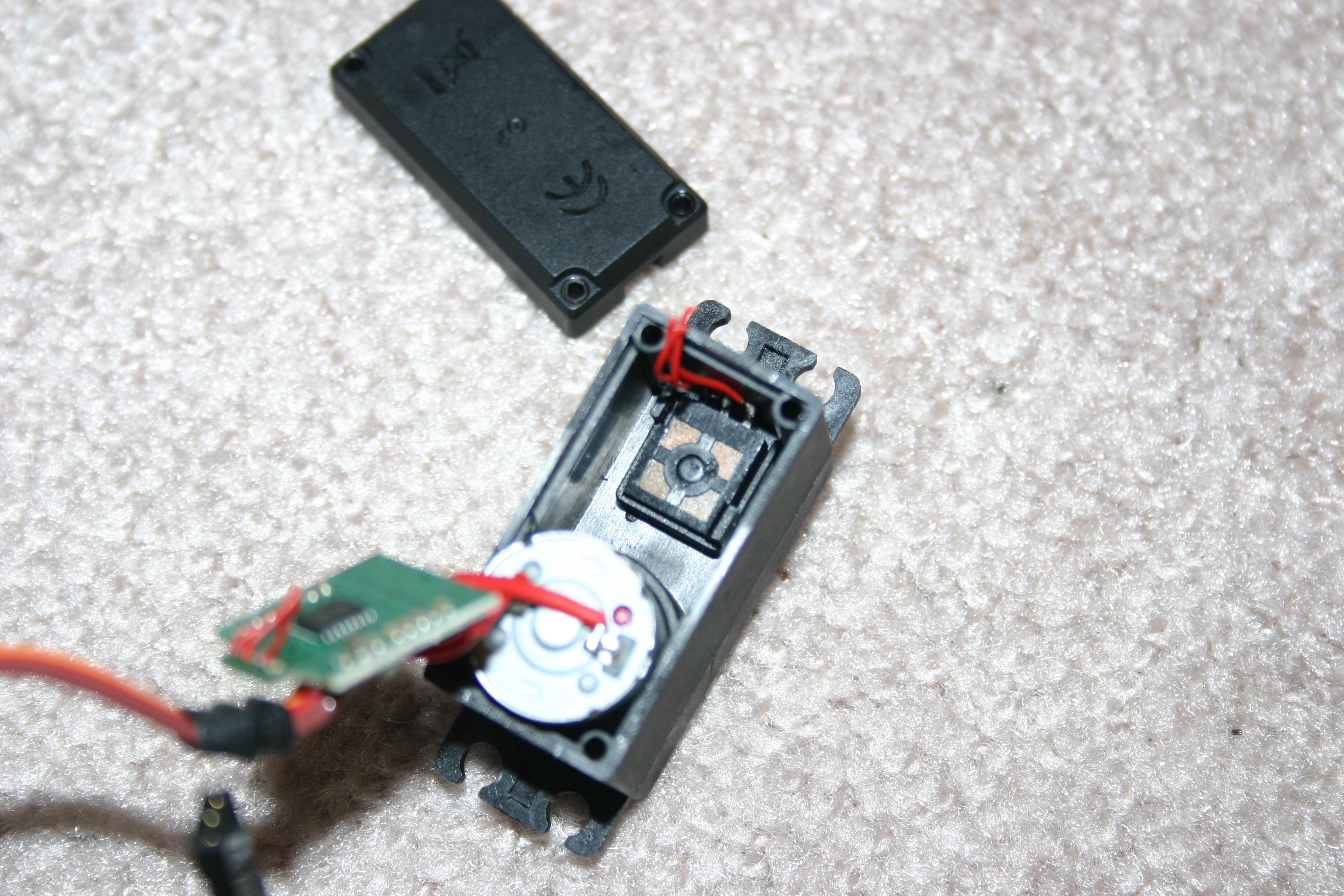
Cut the three wires (under the circuit board) that lead to the potentiometer.
![]()
Remove the potentiometer--it is one of two items that prevent full rotation of the gears.
![]()
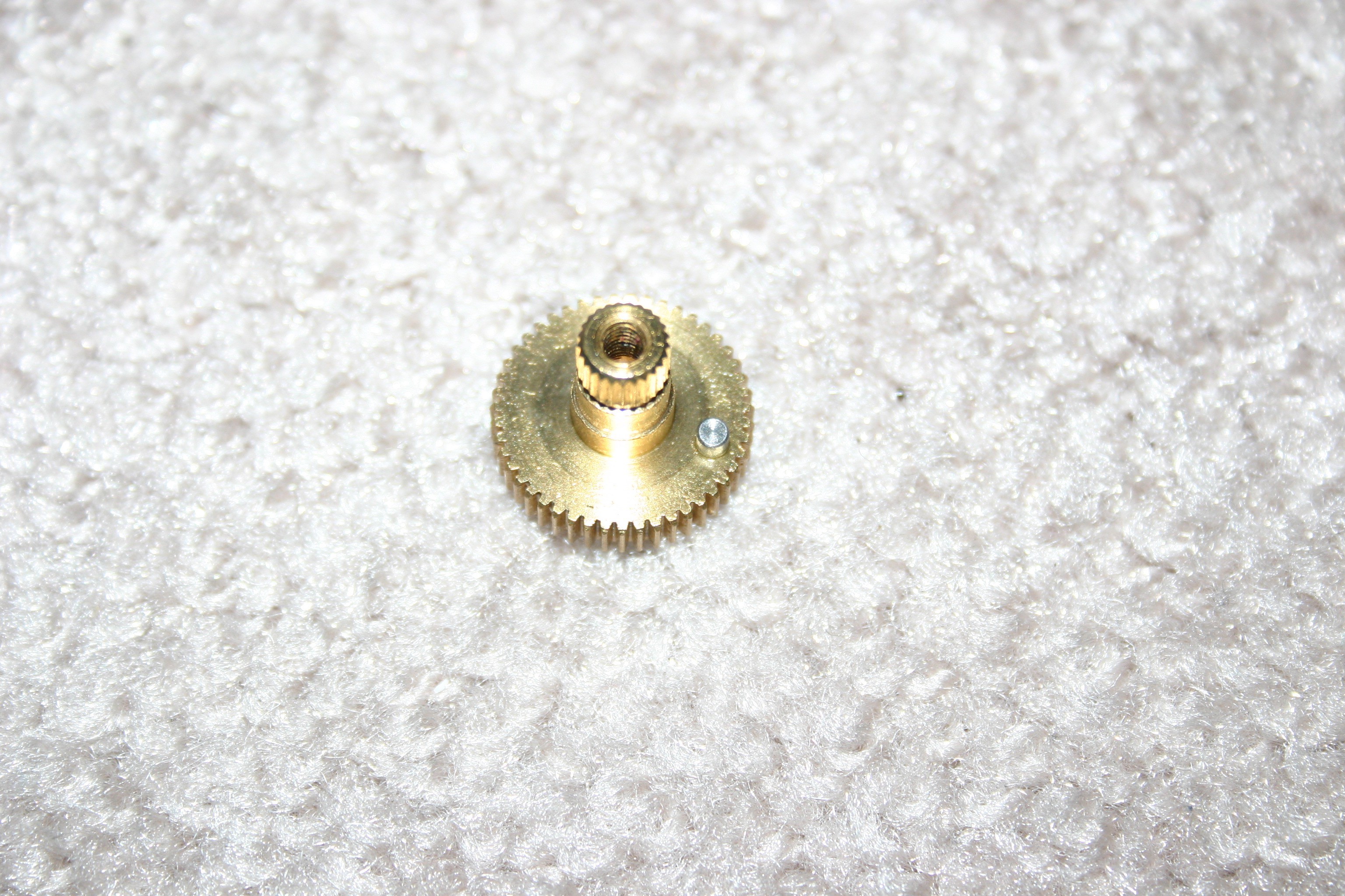
Open the gear cover. On the large brass gear, there is a pin protruding. Lift that pin out (it should remove easily).
![]()
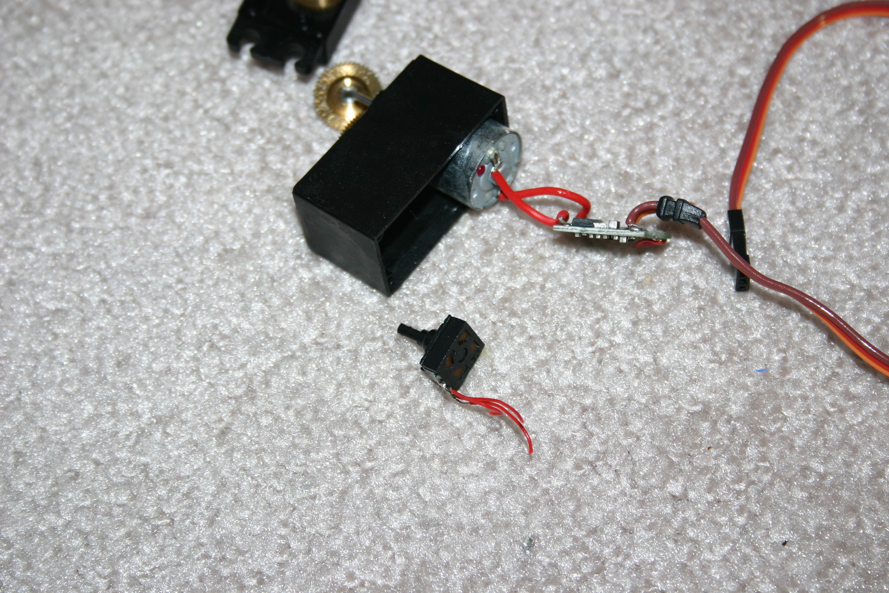
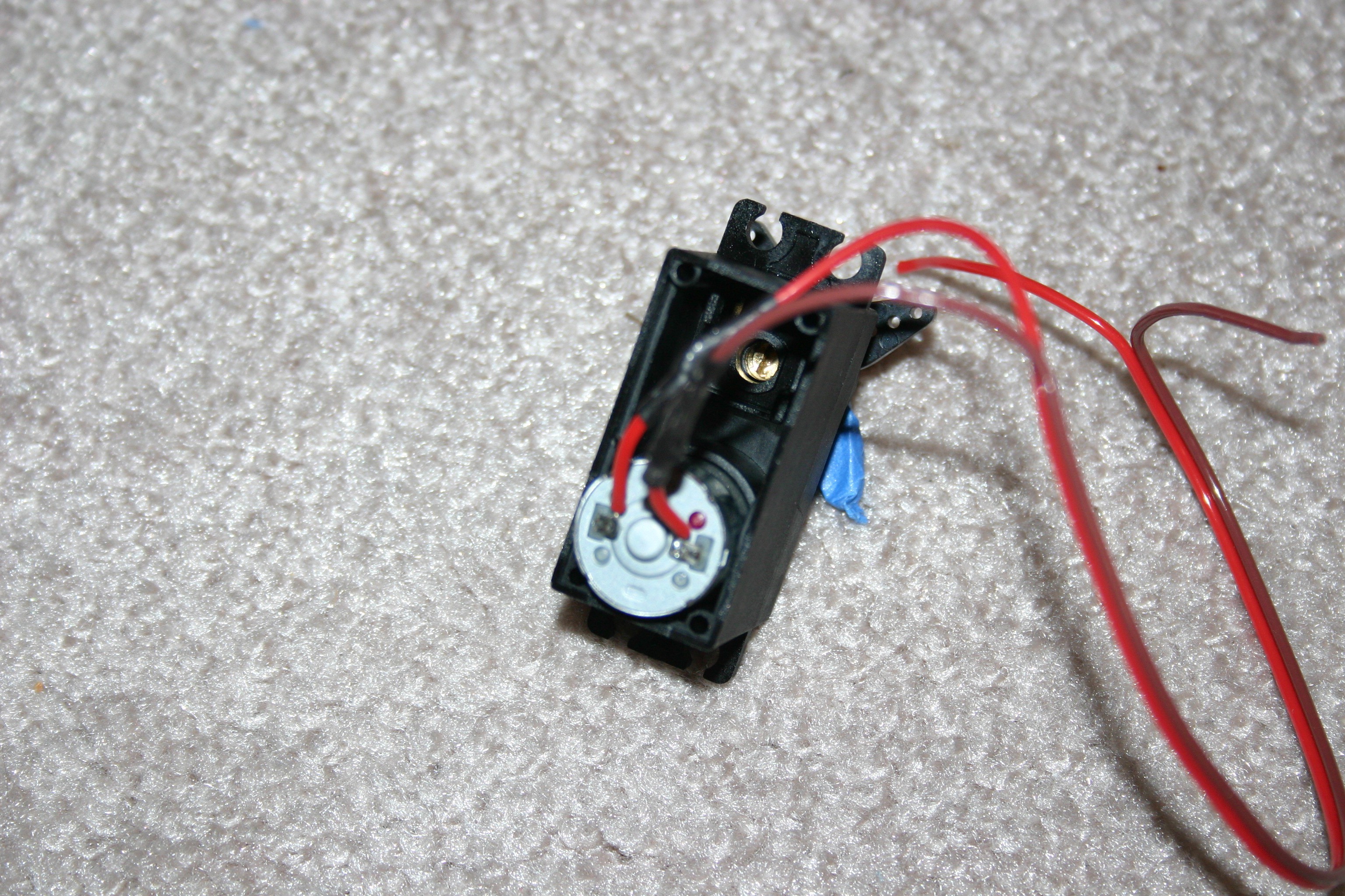
Remove the circuit board by cutting the two red wires that lead to the motor.
![]()
Solder connecting wires from the motor (about 10 inches long).
![]()
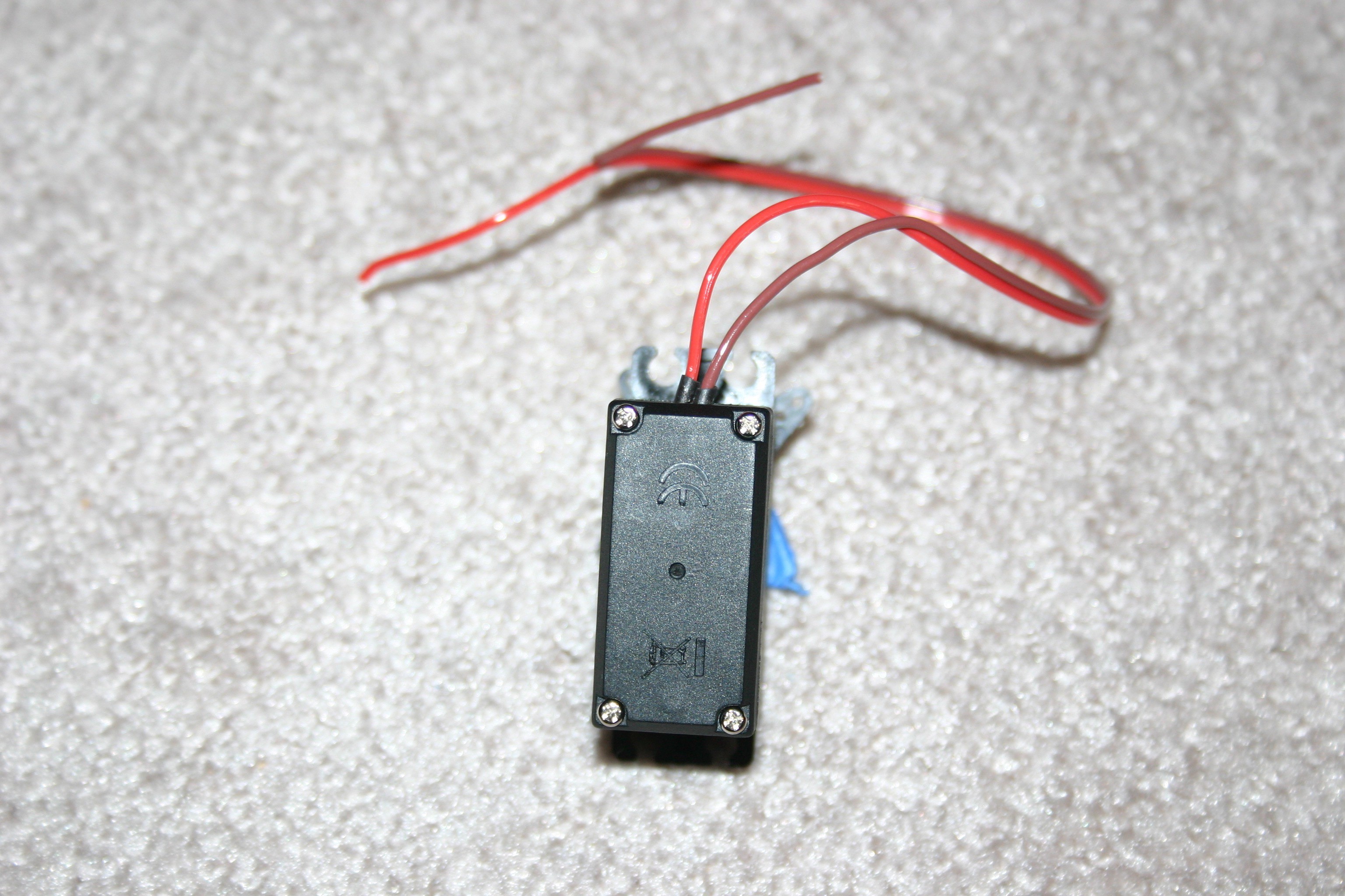
Close the motor and screw everything back together.
![]()
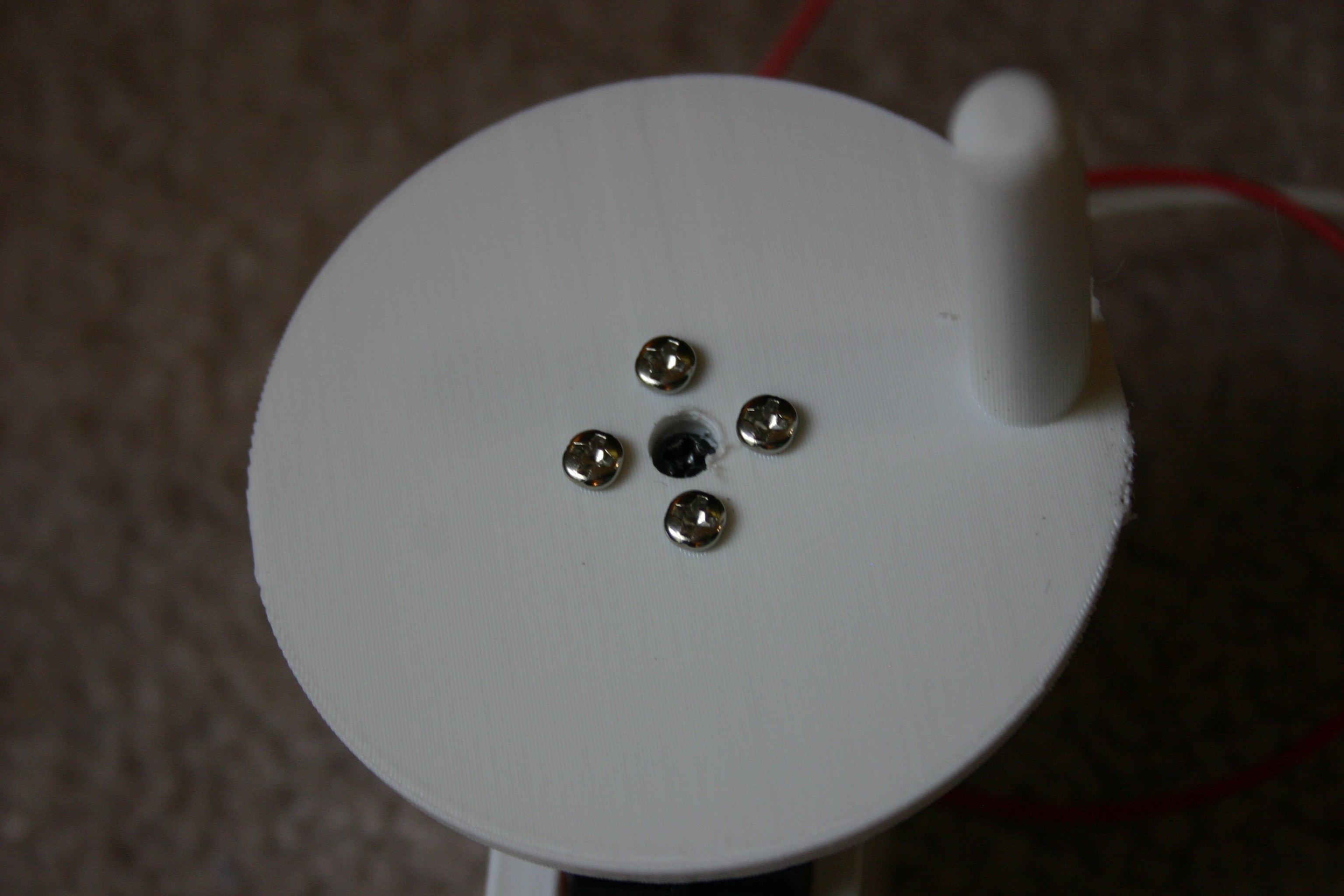
Fasten the crank to the servo horn, then secure the motor in the servo mounting bracket. Attach the crank to the servo motor shaft.
![]()
Screw a terminal block to the plywood base. This block will allow little makers to move the wires around if they elect to mess with them.
![]()
Connect the wires from the servo motor (generator) to the motor. The belt should move when you turn the generator. Switch the red and black wire positions if the direction of cranking does not match the movement of the belt.
![]()
-
Robot People
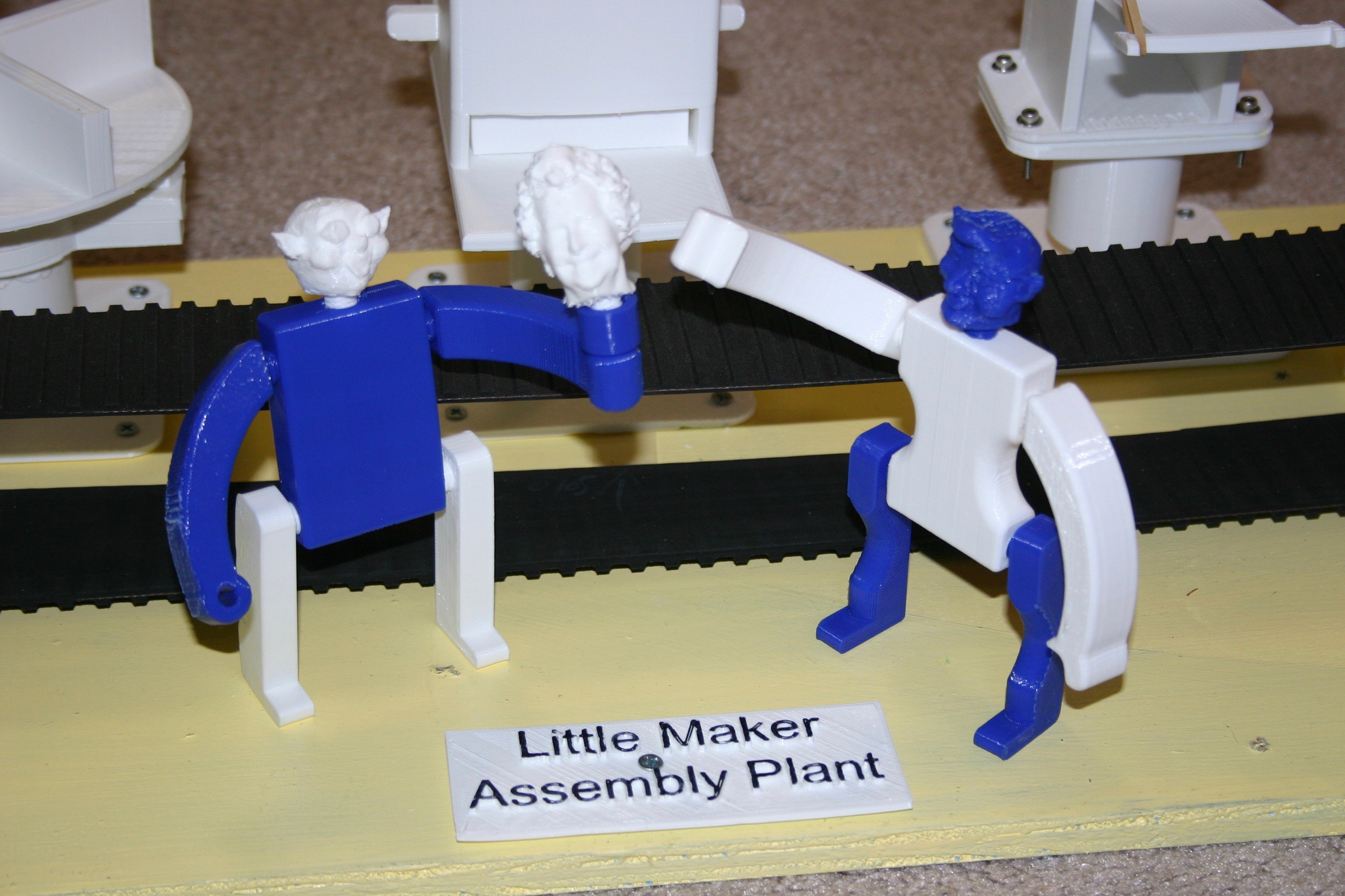
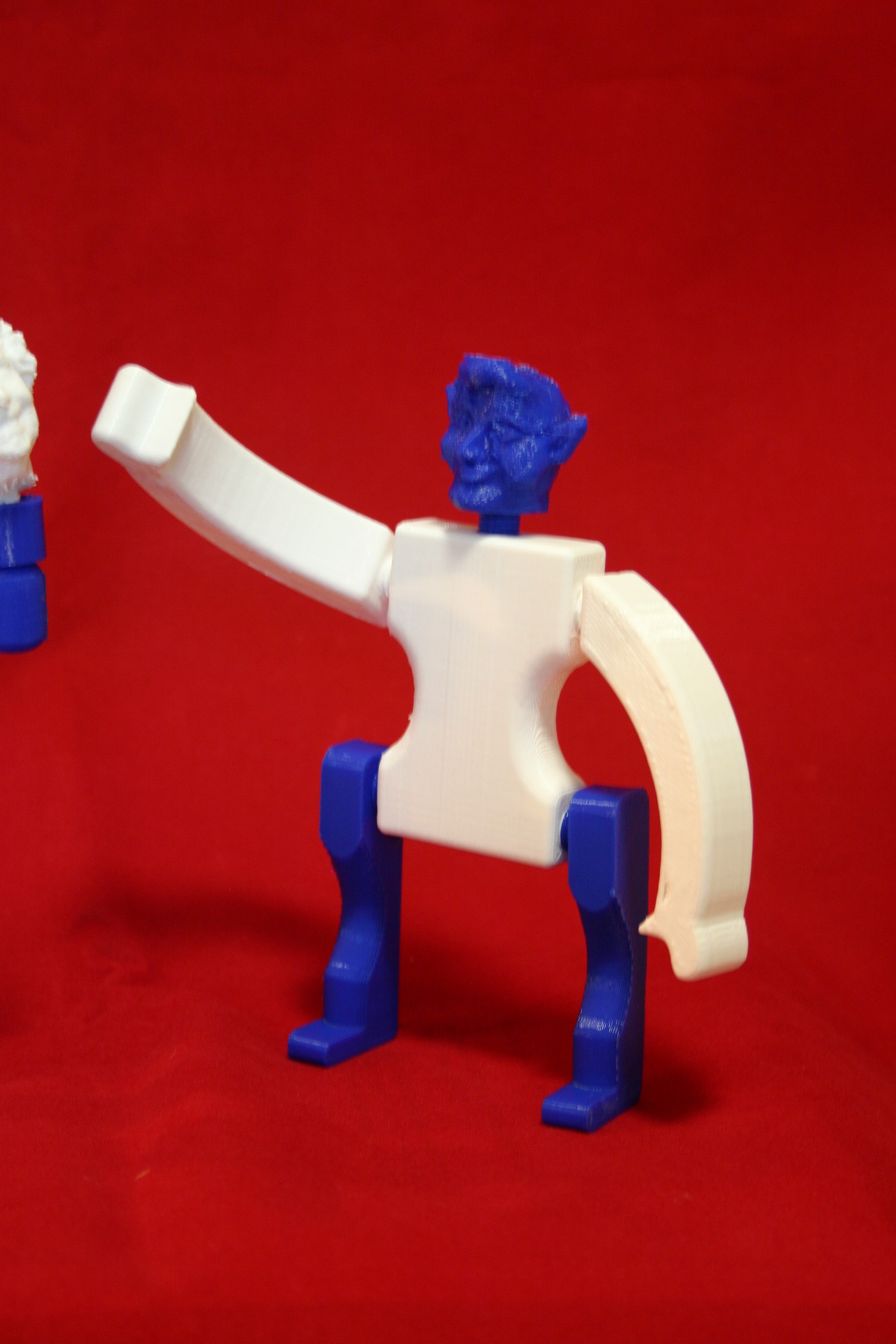
04/20/2018 at 13:35 • 0 commentsWe need something to assemble on the line, so I came up with "robot" people. There are two leg styles, two arm styles, two body styles, three head styles and a cup to fit one of the arms.
![]()
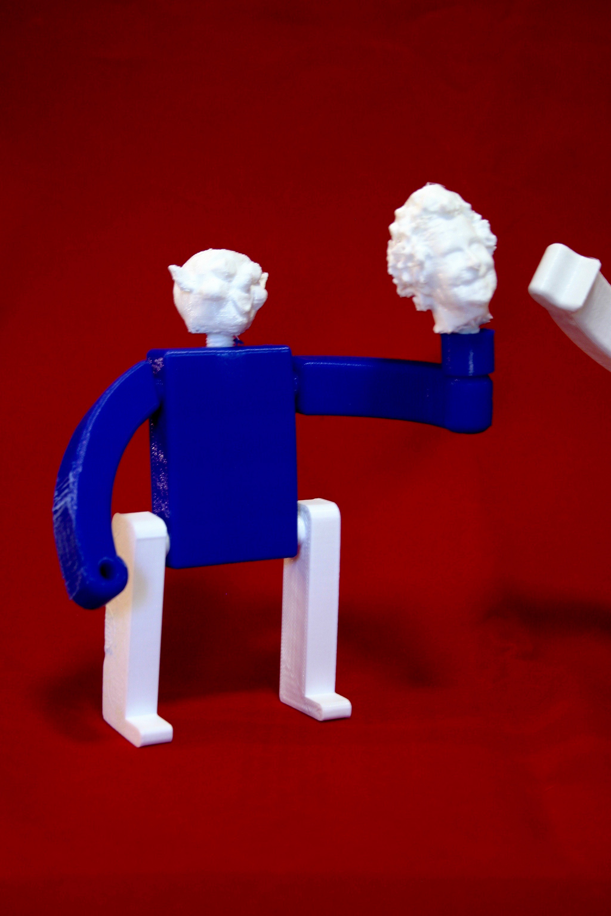
The 3d print files are available on this site. The legs, arms and head screw into the body (legs must go in before the arms). My favorite is Mike's head (my head). Using a 3d sense scanner on a tripod, I slowly turned around in a low back office chair and scanned my head.
![]()
The other heads came from elves in Santa's Shop. If the parts are printed in different colors, even more variations can be produced.
![]()
-
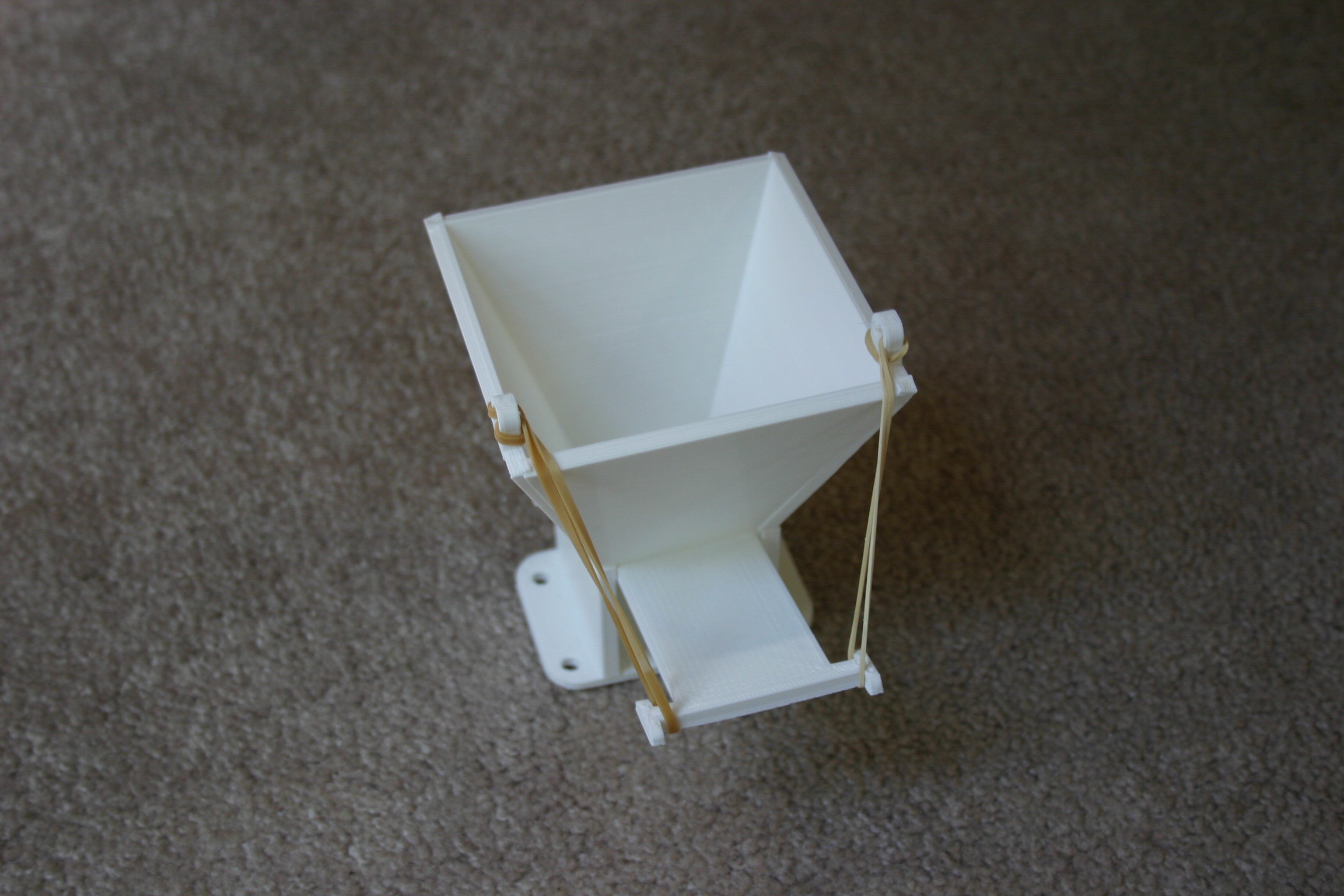
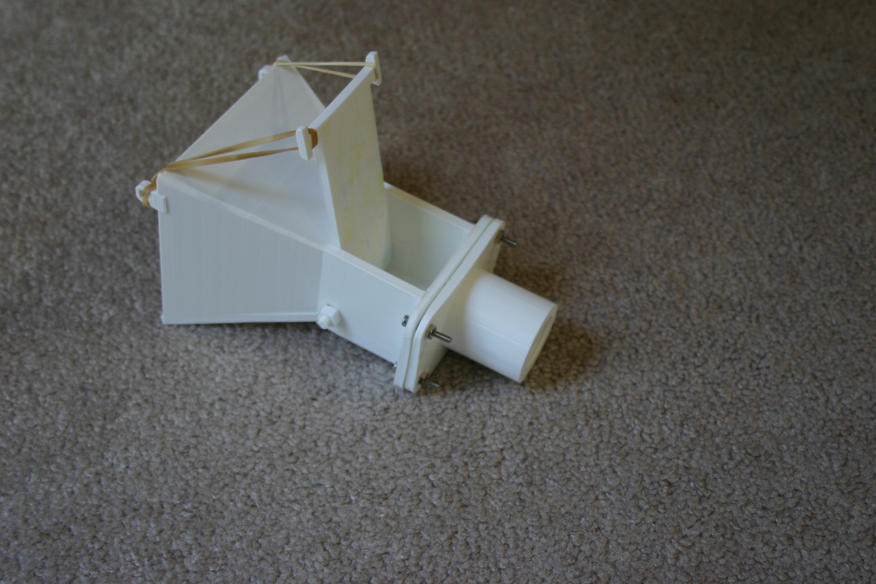
Hopper Module
04/19/2018 at 21:09 • 0 commentsIn this module, I fill the hopper with robot heads. Pulling down on the release lever (held up by rubber bands) allows a head to come out for the assembly process.
![]()
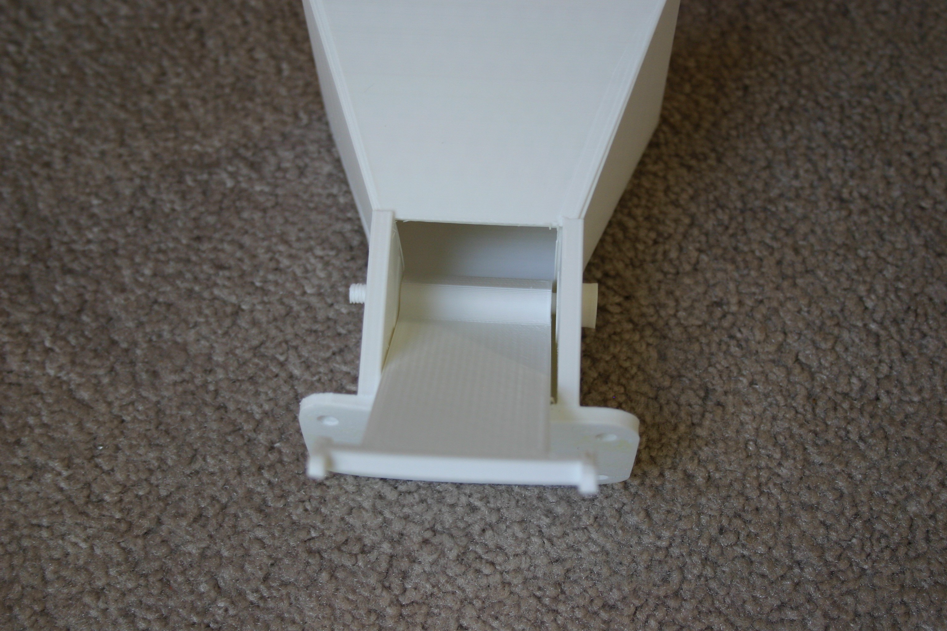
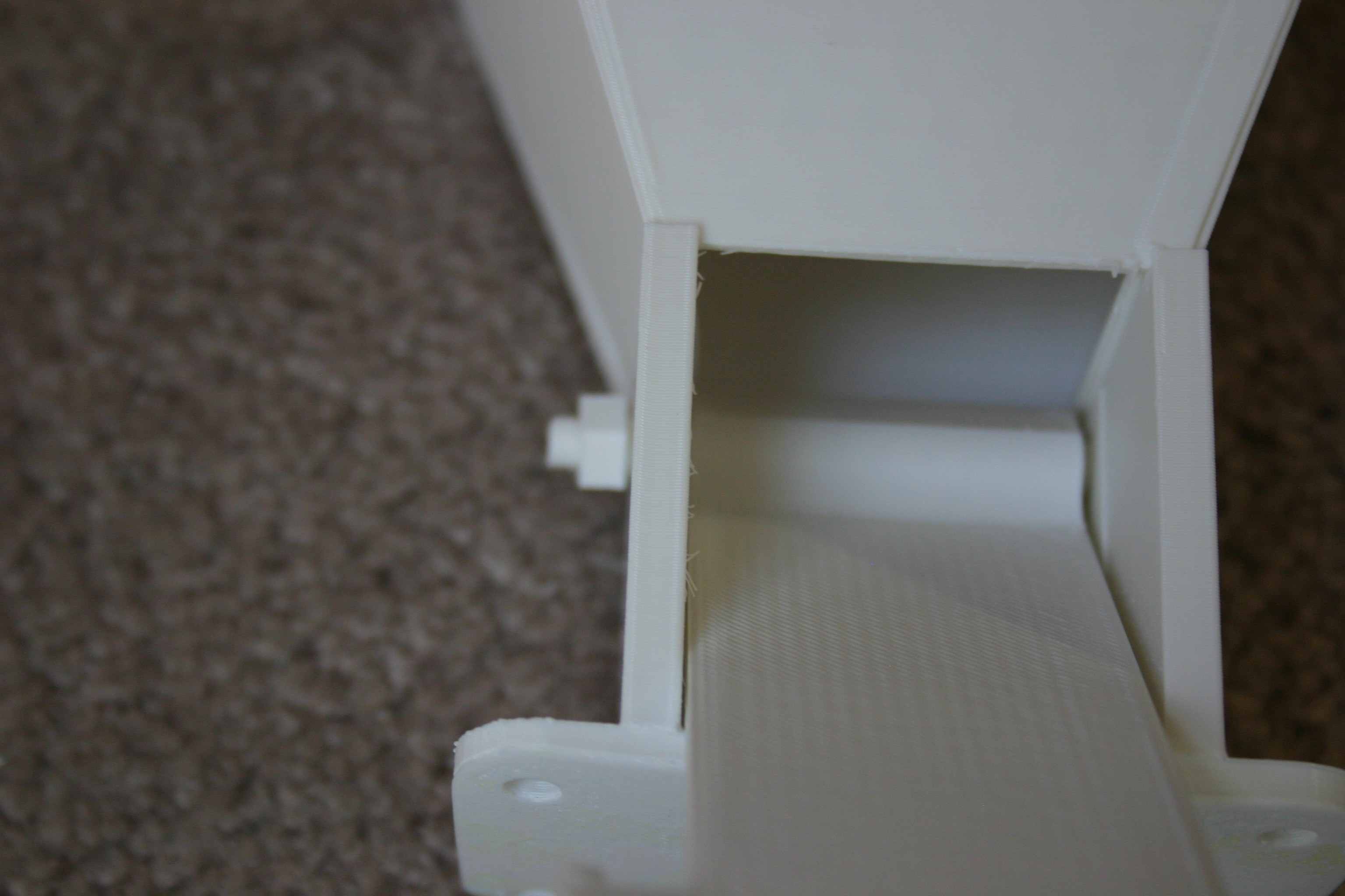
Insert the hopper release bolt through the hopper chute and hopper release.
![]()
Add the nut to the end of the release bolt.
![]()
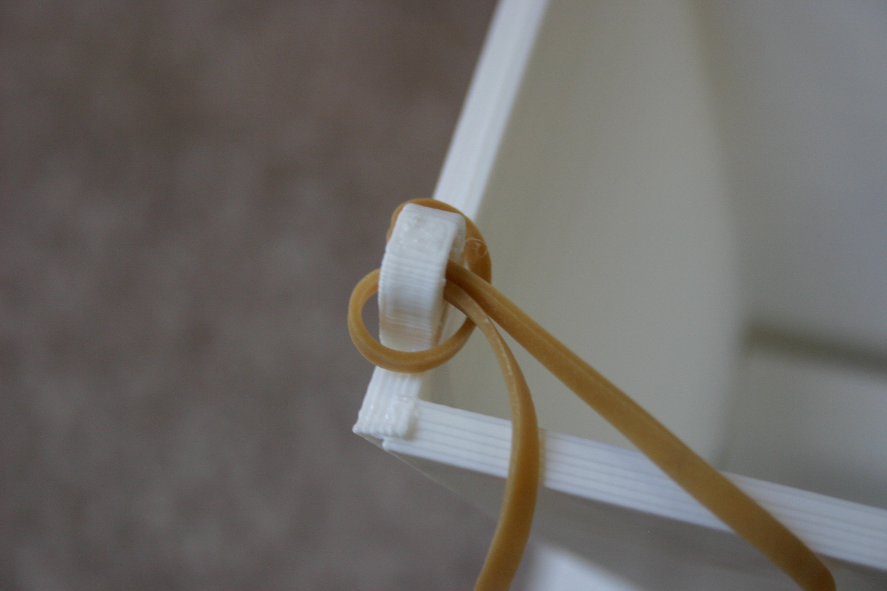
Insert rubber bands through the hooks at the top of the hopper.
![]()
Place the other end of the rubber band around the hopper release. Attach the hopper thread base to the hopper chute with nuts and bolts.
![]()
Thread this into place on the main board, fill it with parts and you are ready to dispense!
-
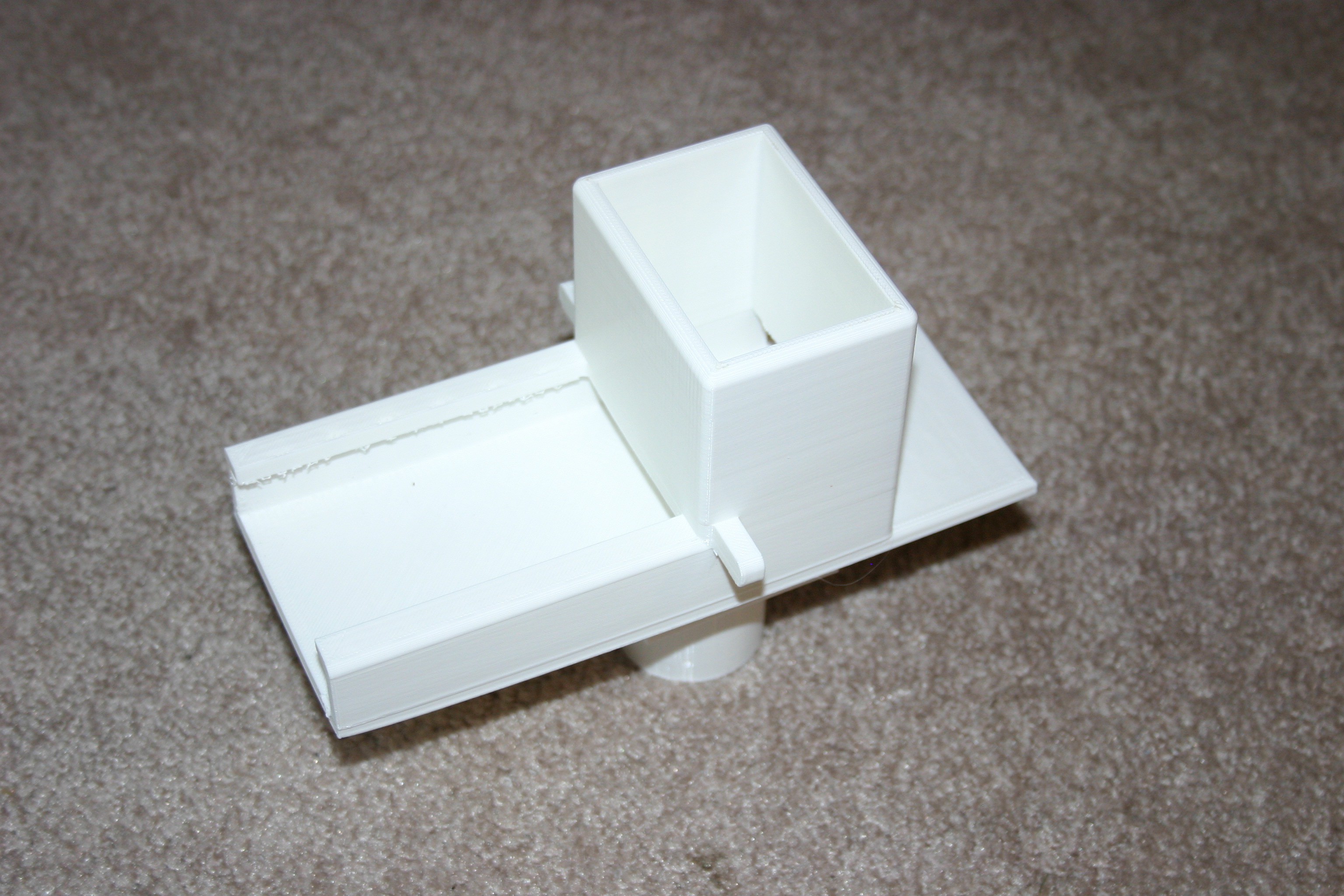
Tray Push Module
04/19/2018 at 18:40 • 0 commentsIn this log, I show how to make the "Tray Push Module." This module screws onto the "bin base." When the tray is filled with robot bodies, the pusher at the rear of the module can be pulled back and pushed forward to release a new body in the front landing tray.
![]()
Print the tray tower.
![]()
Attach the tower to the tray base. I melt them together using a soldering iron.
![]()
Screw this to a "bin base," insert the pusher in the rear slot and you are ready to load the tray with robot bodies (another log--coming soon!).
-
Turntable Module
04/10/2018 at 21:22 • 0 commentsHere I'll build a module that can be rotated by hand and easily attached or removed from the conveyor belt assembly.
Start by attaching the bin base to the conveyor belt board using four #6 x 3/4 inch wood screws.
![]()
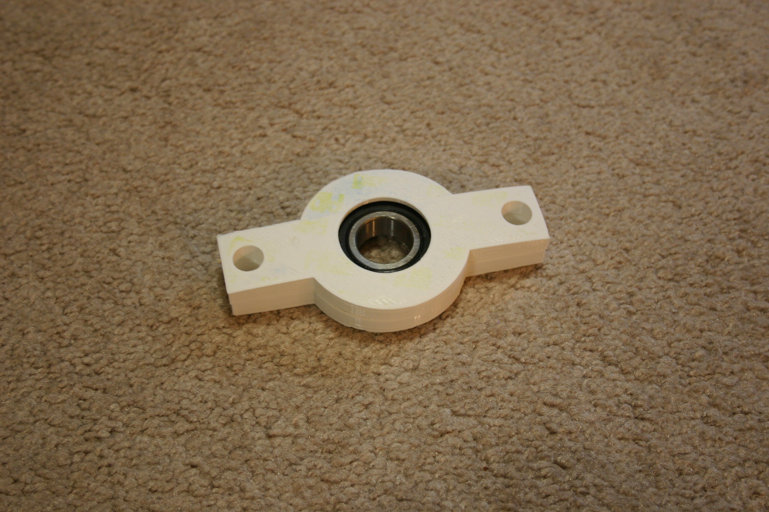
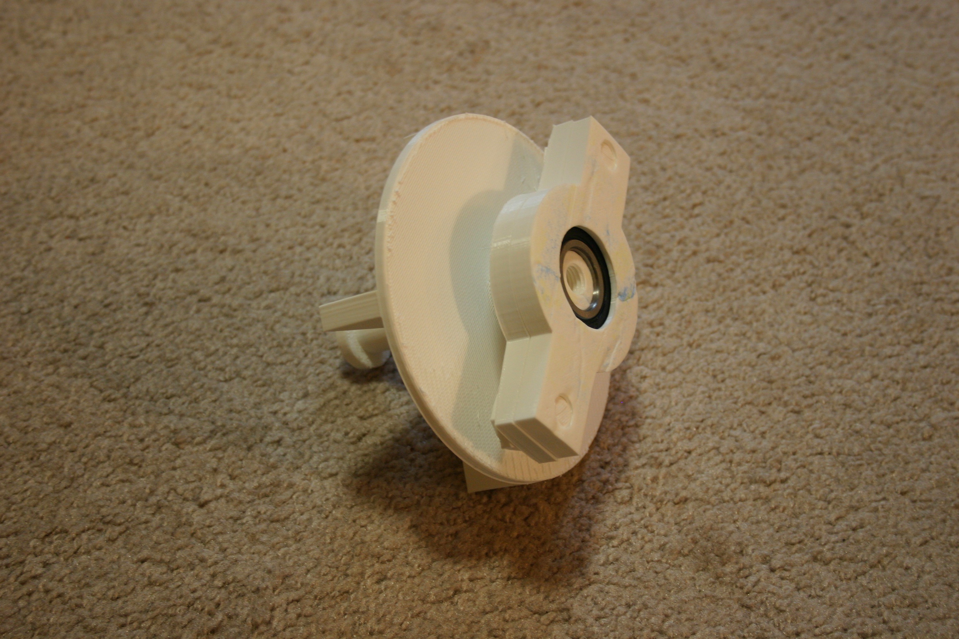
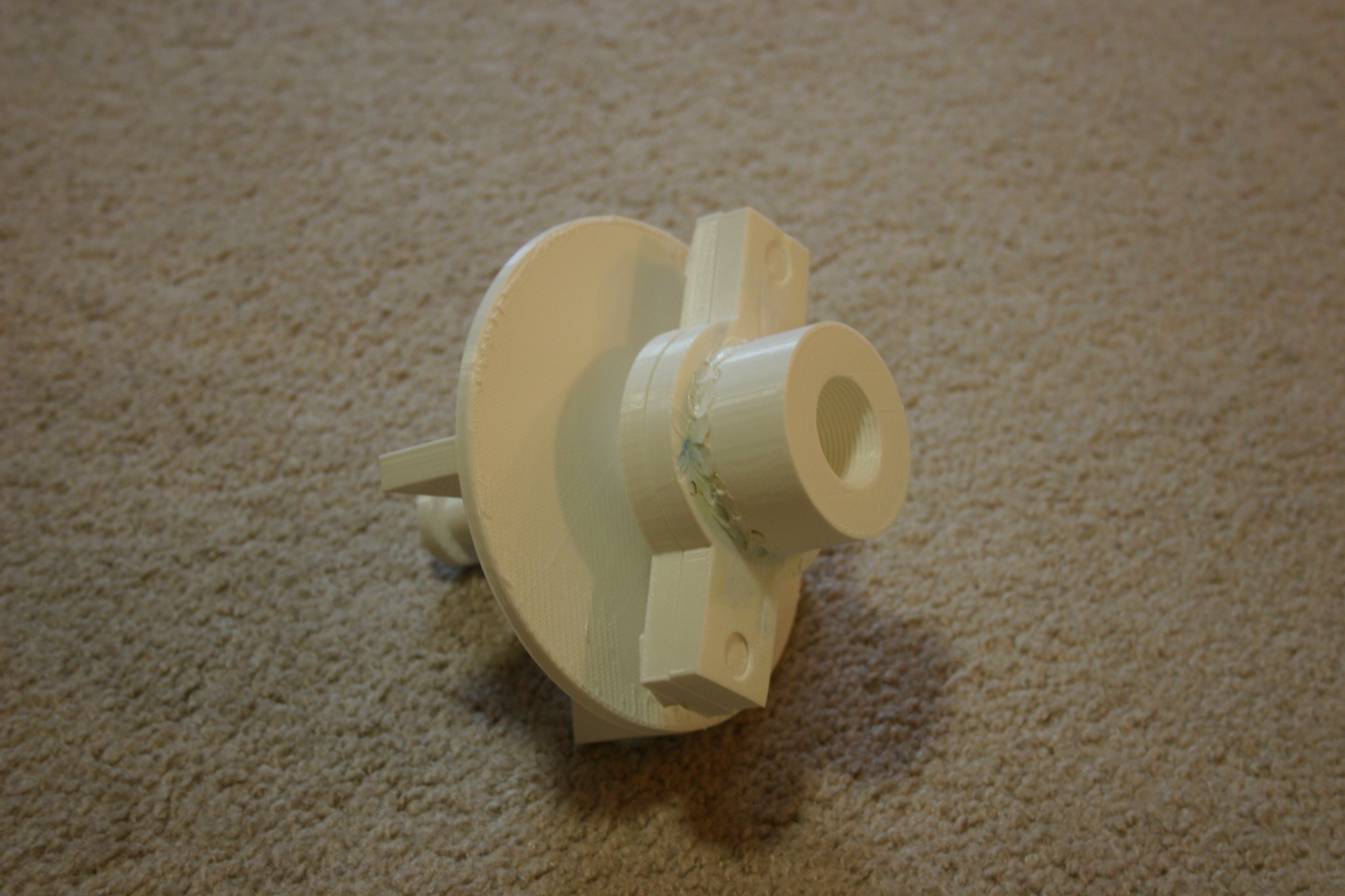
Next, print the "bearing bottom" piece.
![]()
Insert the bearing.
![]()
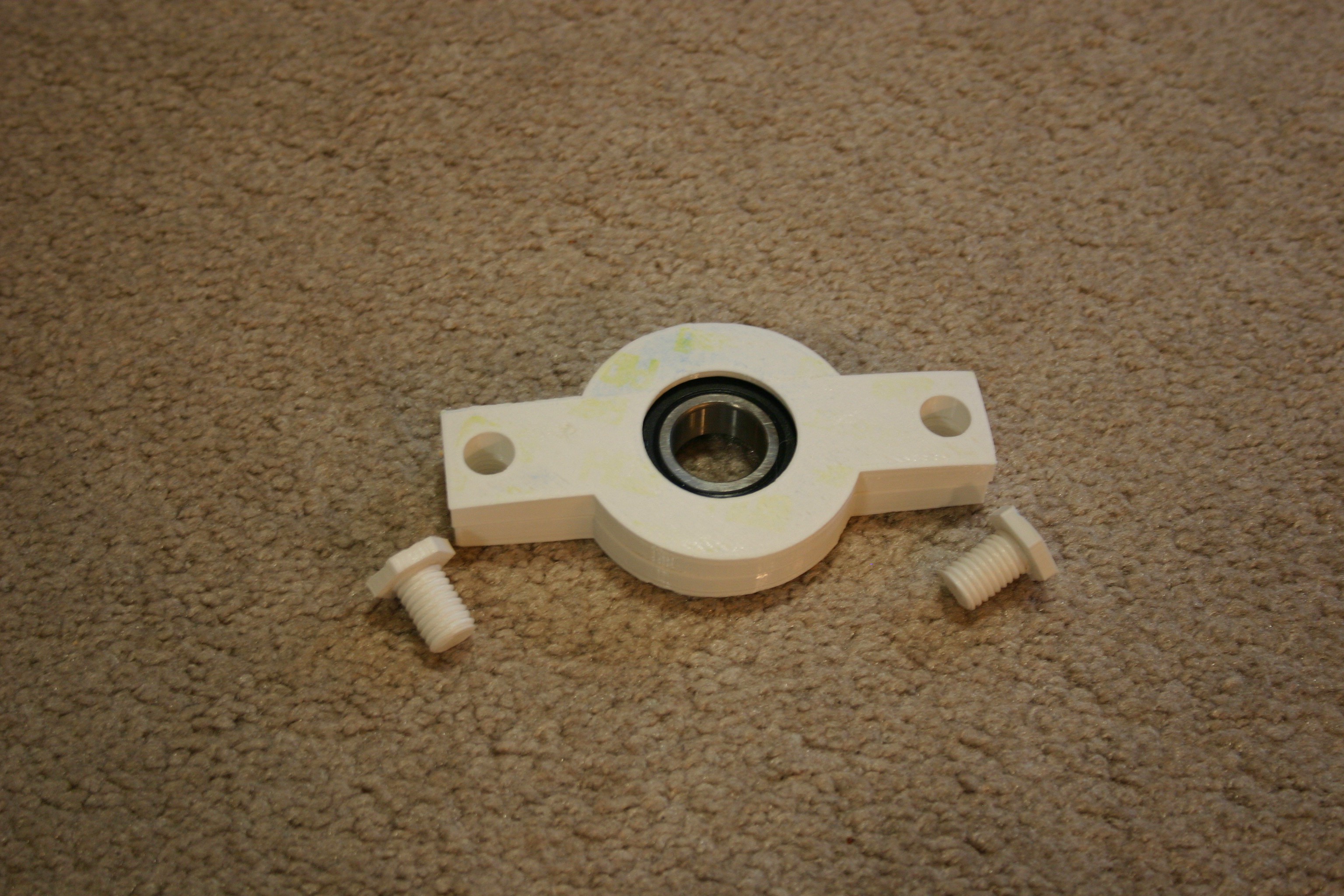
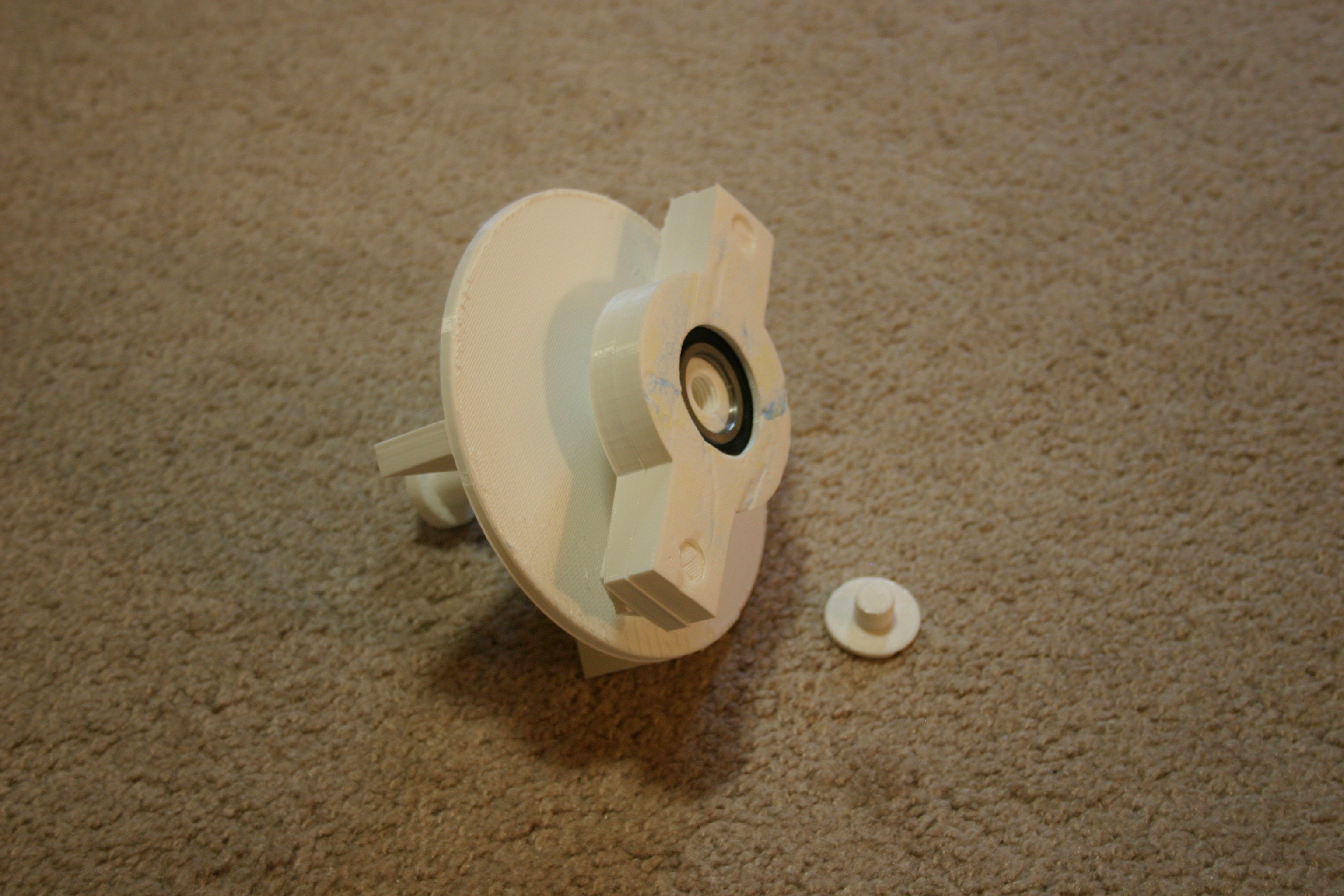
Add the bearing top to the bearing assembly. The top piece has no screw threads in the outer holes.
![]()
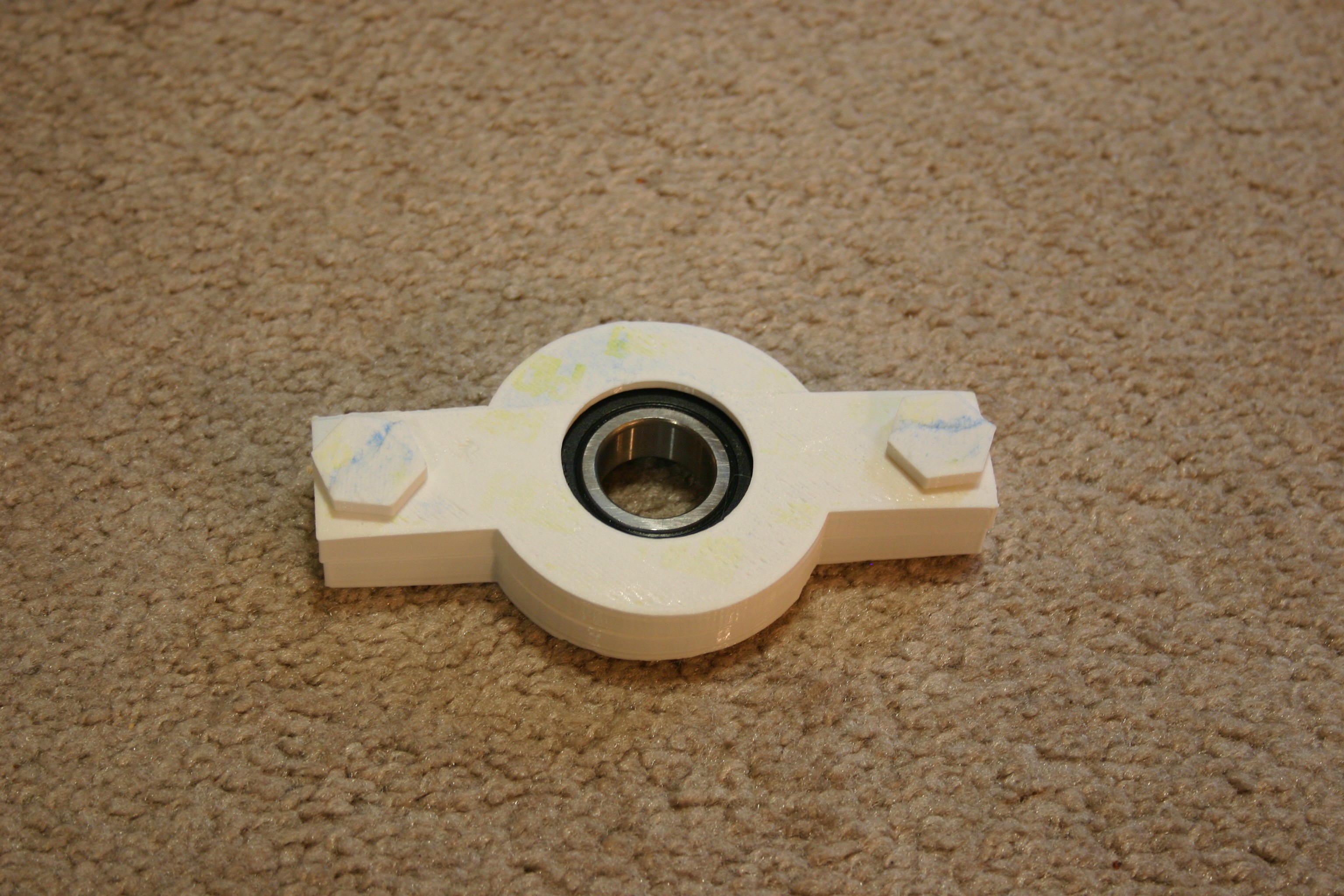
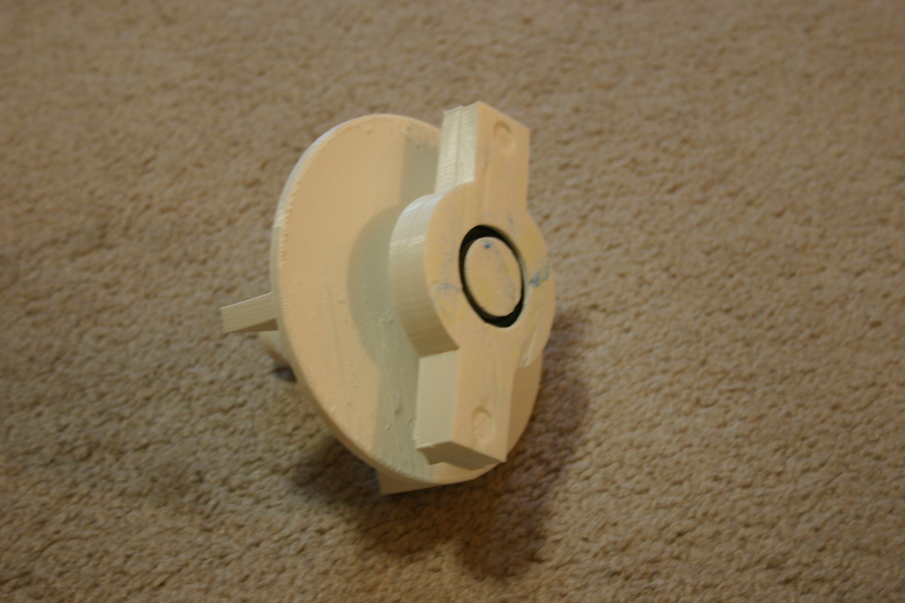
Secure the assembly by screwing the two bolts into the end holes.
![]()
![]()
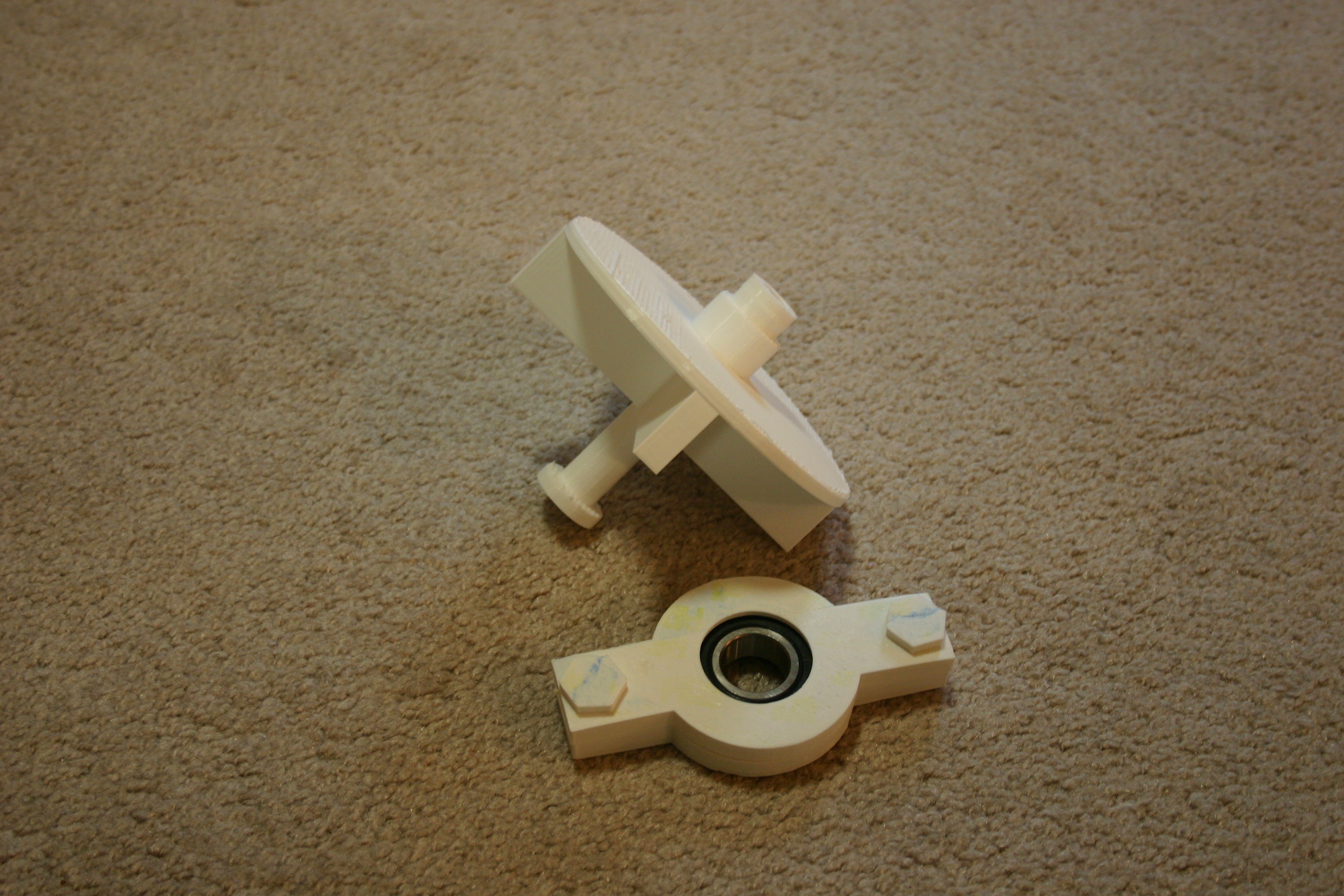
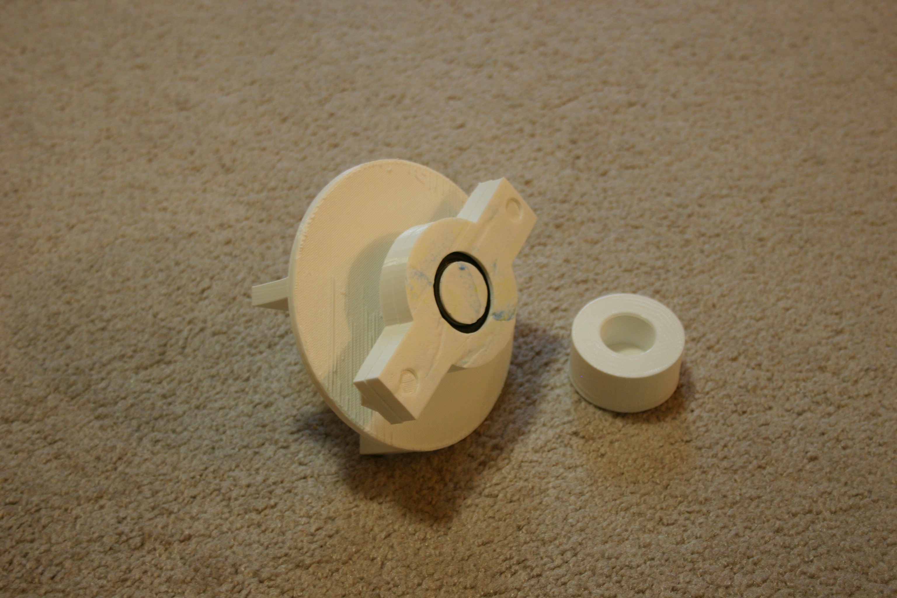
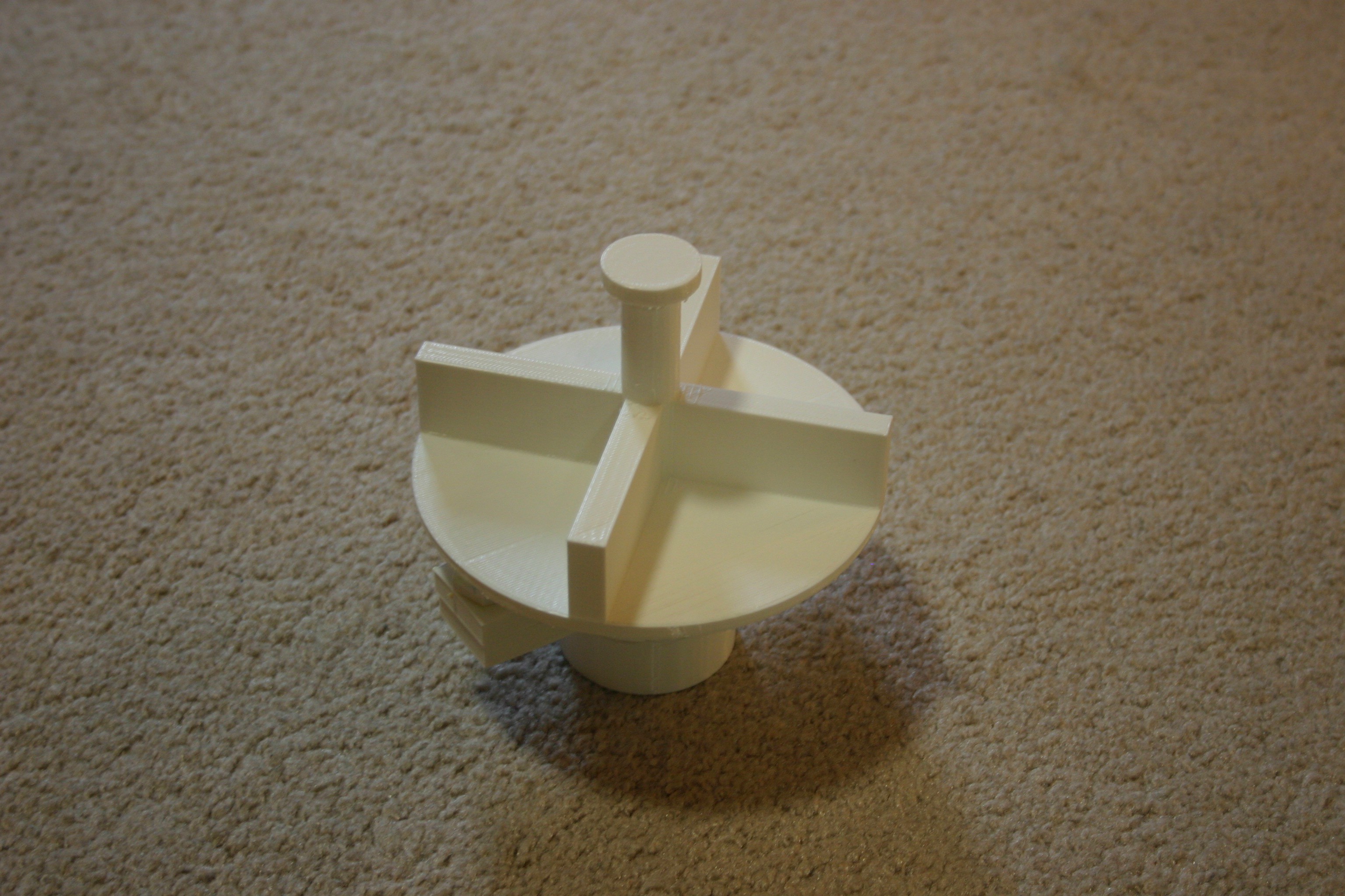
Print the bin spin combo and bring it to the bearing assembly.
![]()
Press the "bin spin combo" into the bearing assembly.
![]()
Bring the "gear lock" to this assembly and screw it into the bottom of the "bin spin combo."
![]()
![]()
Attach the "module attach" piece to the above combo. I melt them together using a soldering iron, though I suppose they could be glued.
![]()
![]()
The completed module, from the top, looks like this.
![]()
The module can be easily screwed onto or off of the conveyor belt base.
![]()
-
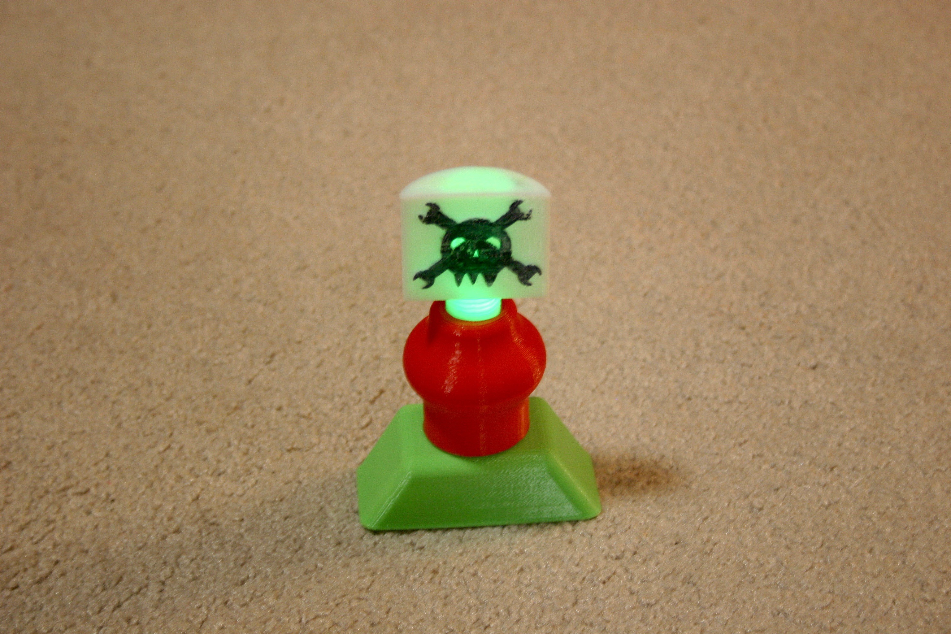
Building the Hackaday Bot
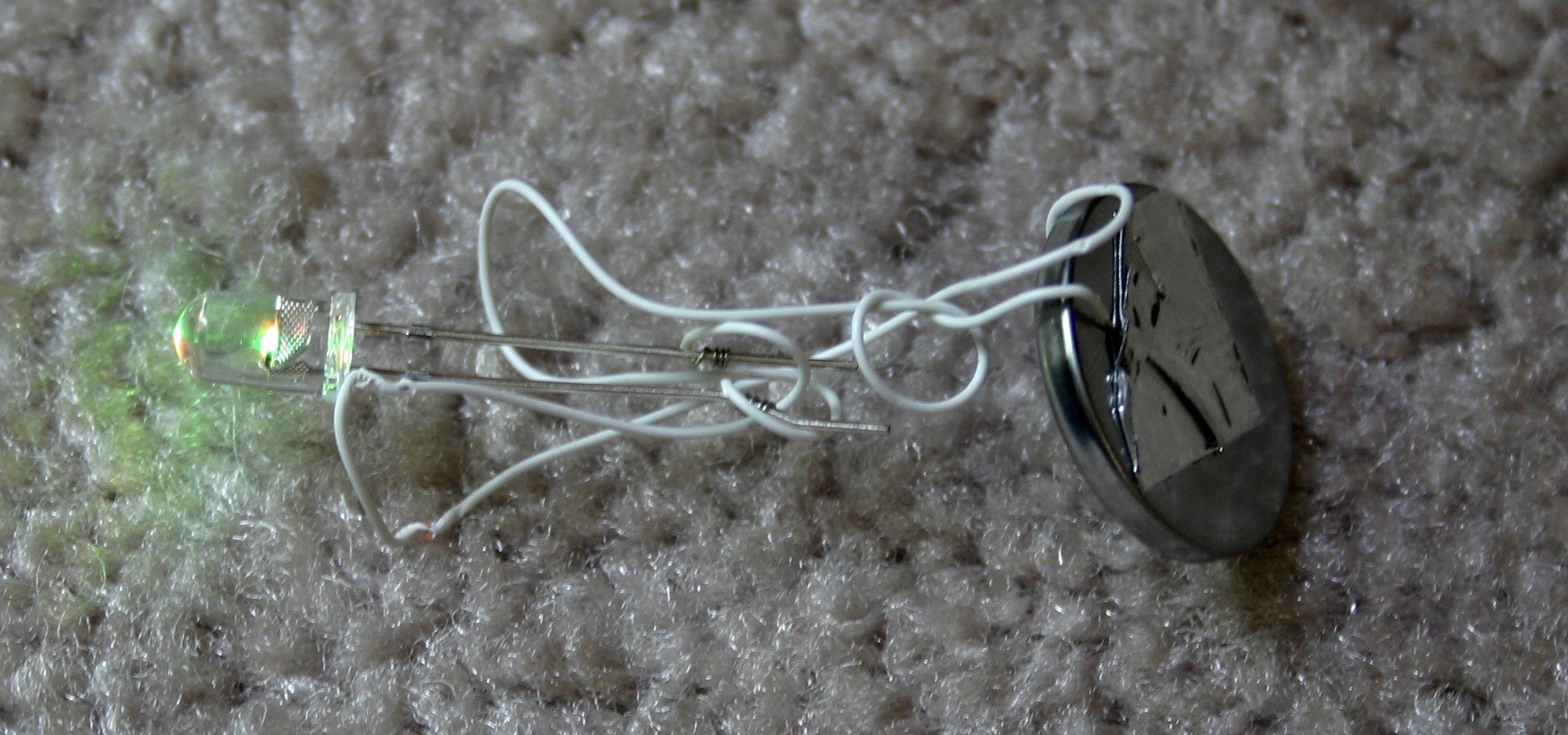
04/04/2018 at 21:10 • 0 commentsThis bot was quickly put together as a prototype toy for the assembly line.
![]()
I used wire wrap wire to extend the led legs to the battery. Aluminum duct tape was used to secure the wires to the battery.
![]()
Now, for the 3d part printing details.
The head should be scaled to 40% of original size.
The mid body should be scaled to 115% of original size.
The legs should be scaled to 110% of original size.
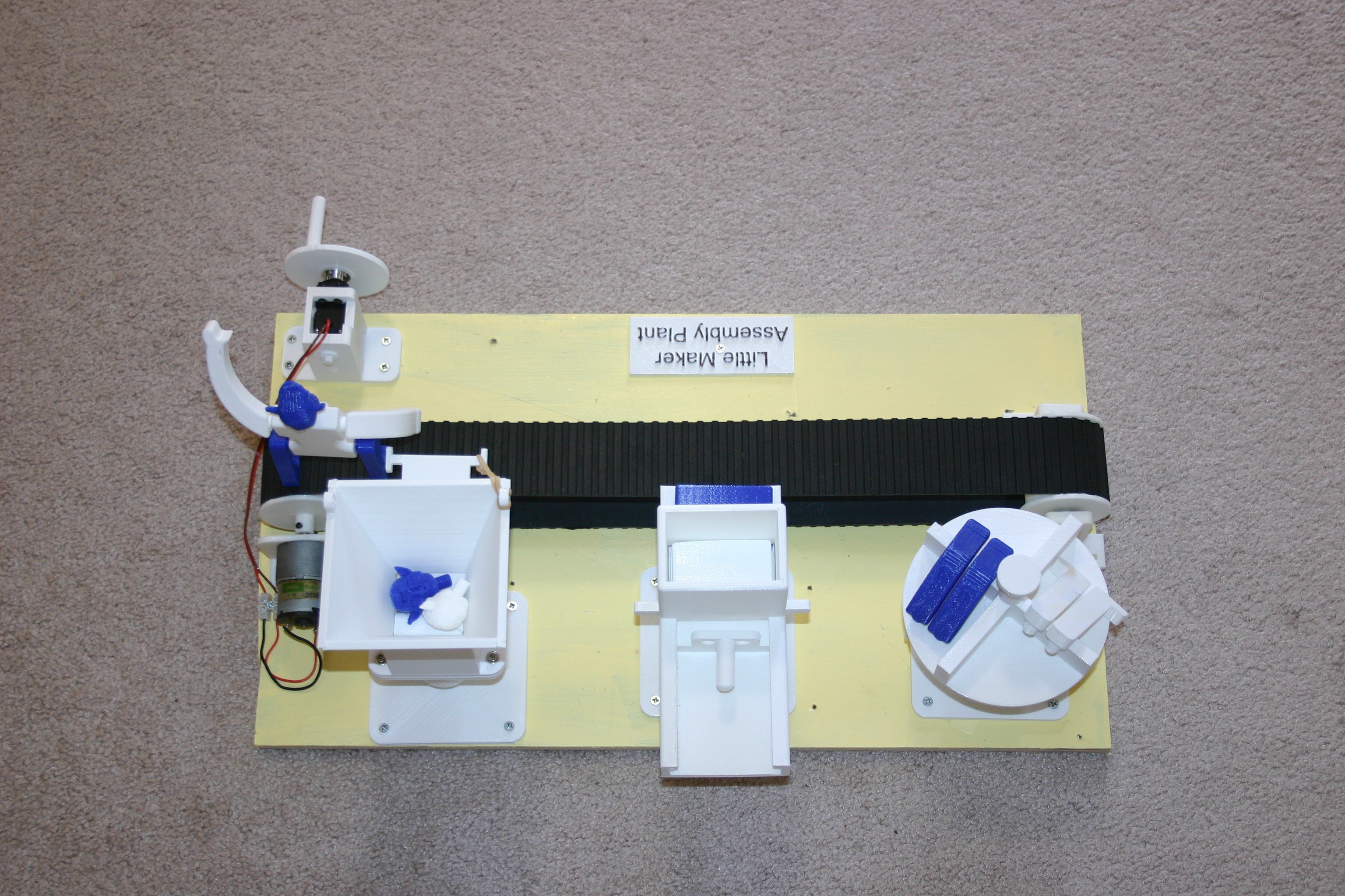
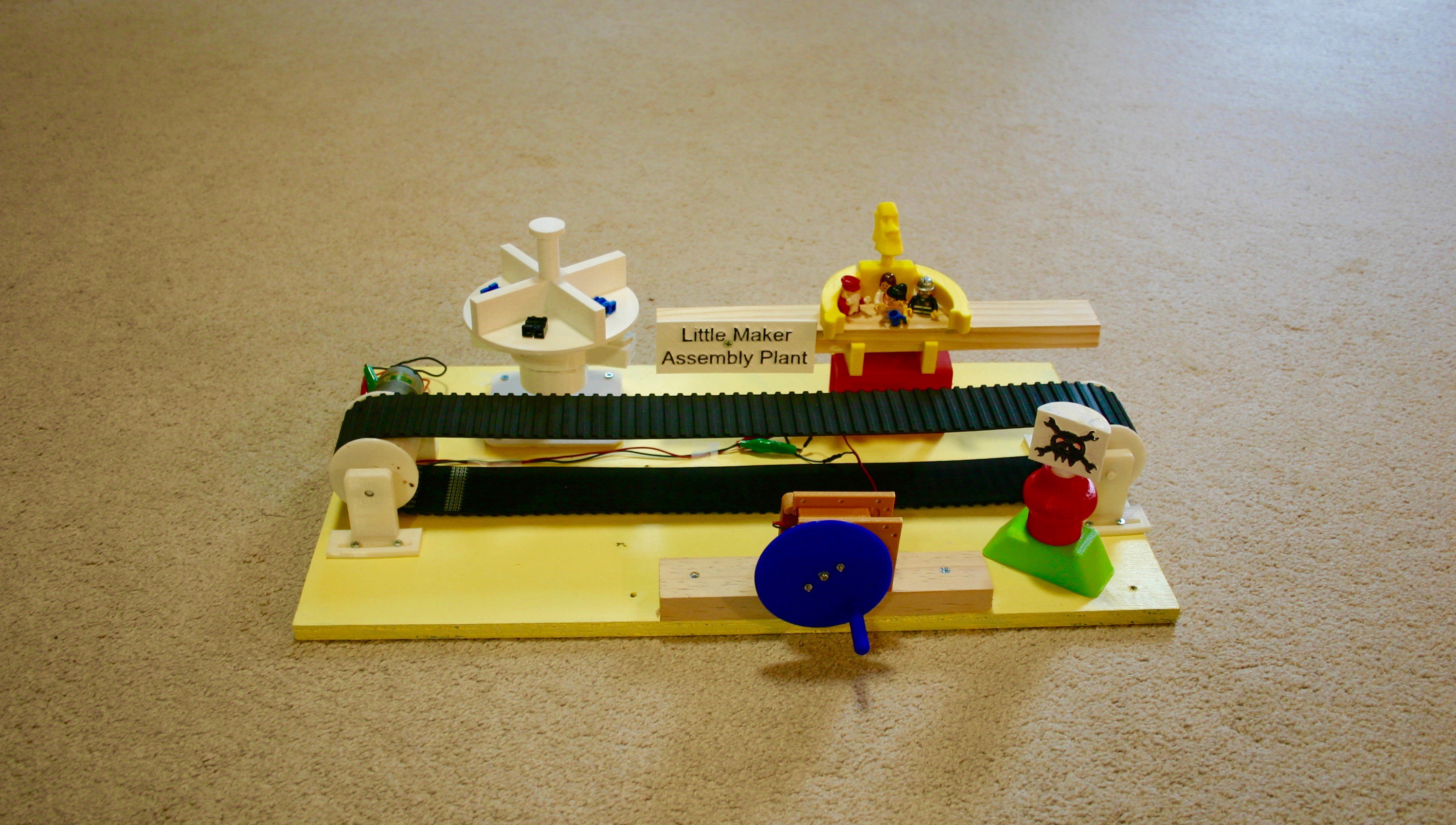
Little Maker Assembly Plant
The future generation, "Little Makers," can use "hands on" assembly toys to fuel imagination.