-
Update - flying extruder
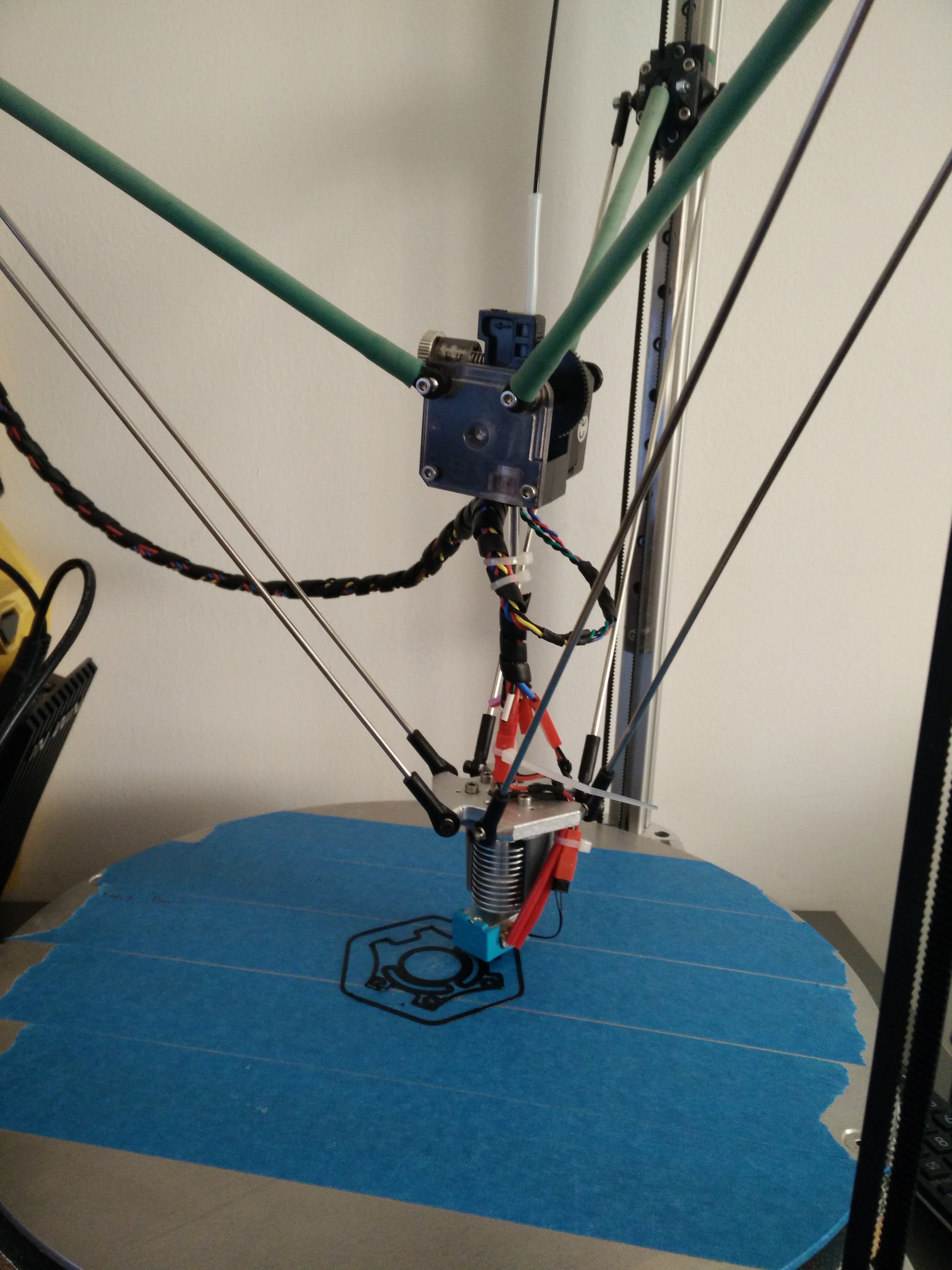
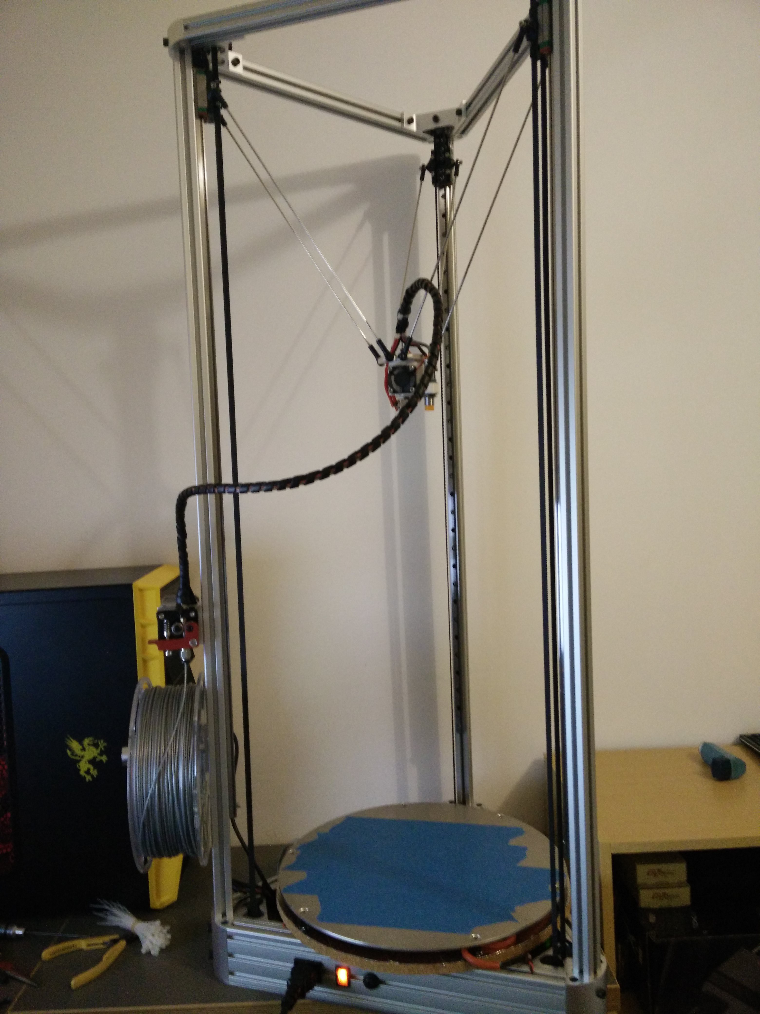
11/11/2016 at 09:17 • 1 commentI have been having trouble with the long pneumatic hose that runs the filament from the extruder top the hot end. My solution is to mount the extruder on catapult elastic.
![]()
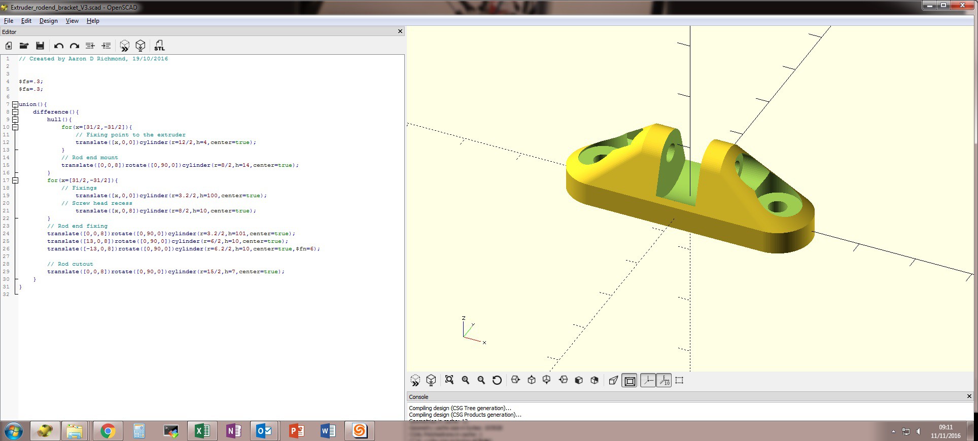
I designed a few basic brackets to hold some standard rod ends, they can be found on thingyverse http://www.thingiverse.com/thing:1836709 this one attaches to the end on the stepper motor.
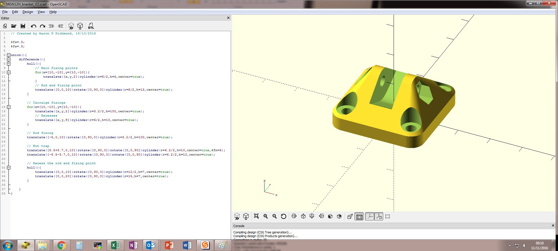
This one is for the MGn12 linear blocks![]()
![]()
The next stages for me is going to be swapping out the 8bit controller for a nice modern 32bit version, i have been having trouble with the arduino based controller pausing while it is doing the kinematic equations to work out the delta triangulation. This causes the nozzle to just stop and overheat part of the print causing blobs of plastic. The 32bit controller should have the grunt to calculate these moves quick enough to keep the print smooth.
-
Update 19-08-2016
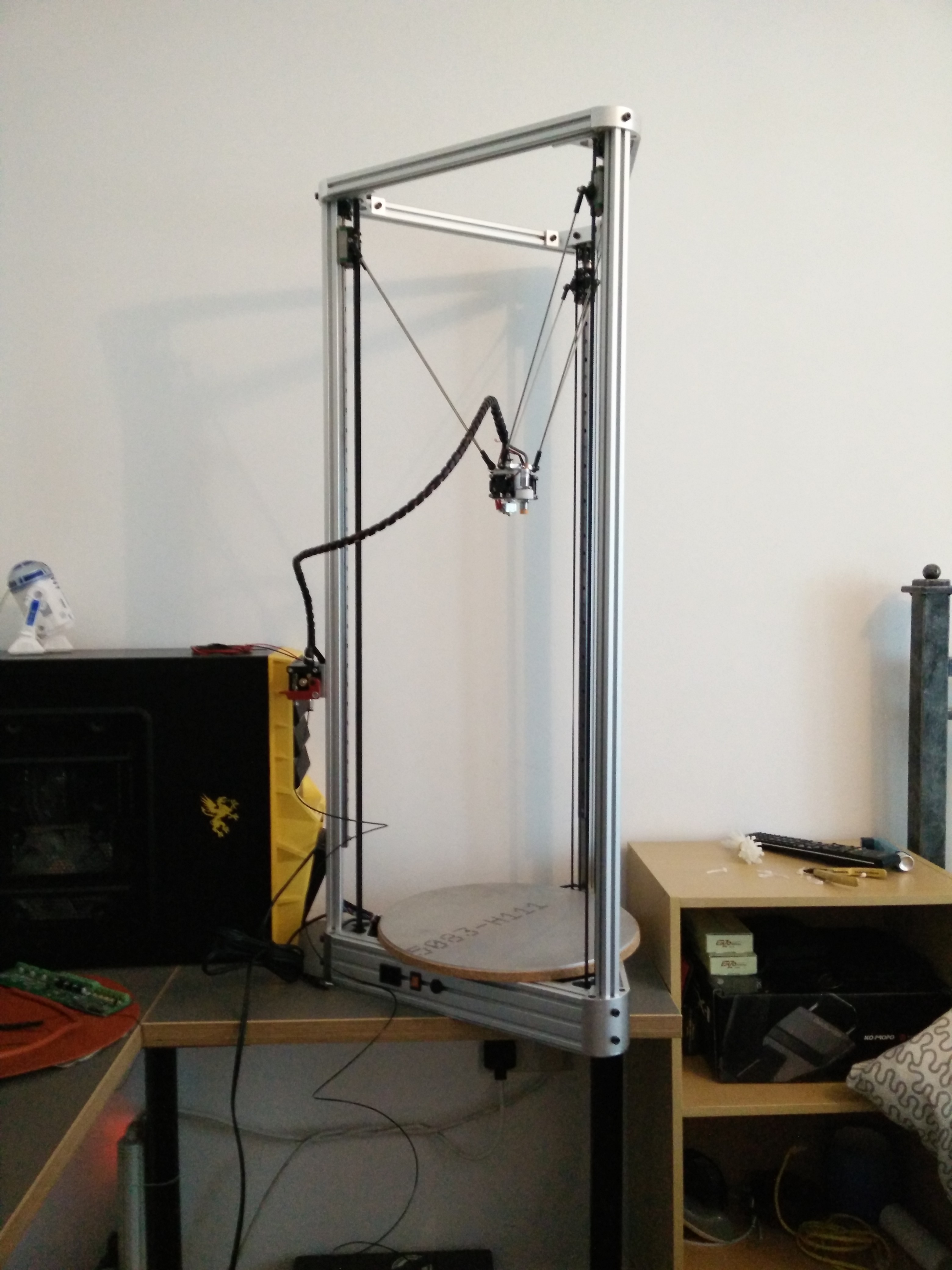
08/19/2016 at 11:28 • 0 commentsHeated bed has been attached for a little while now and i have PLA printing nicely.
![]()
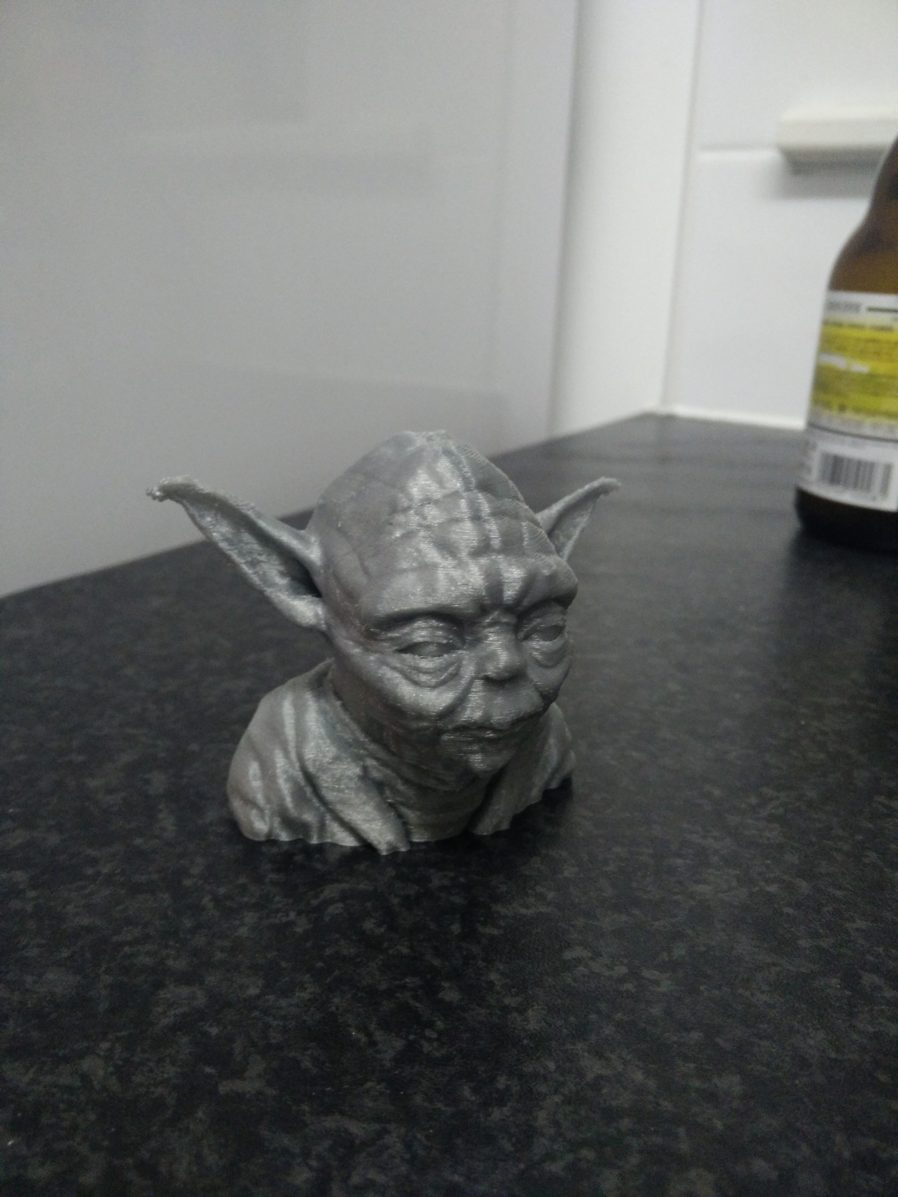
Yoda head in eSun PLA...
![]()
Next things on my list is to move onto PETG filament for its strength, i cannot get this to print quite right...the filament is somewhat sticky compared to PLA and it is adding alot of friction inside my overly long bowden tube.
The plan is to create a flying extruder setup where the extruder is connected to the carriages via elastic, this means i can have a very small bowden tube and potentially remove my current issue.
-
Update, getting there !
06/16/2016 at 12:26 • 0 commentsSo i now have most of the printer together and i attempted a first print, the layering was excellent and then the extruder started slipping !
Tried to turn of the current on my MKS base but to no avail, i have ordered a 5:1 geared stepper to solve my torque issues. I can only guess it is down to my rather long boxden tube.
![]()
I discovered another issue, this one revolves around the auto level function built into marlin. When i run an autolevel my hot end just crashes into the bed, however i can run a G30 (single probe point) and this works...i shall dig further and report my findings.
Still got buckets left to do such as a spool holder, heated bed, mounting the bed (maybe some magnets to hold it on so i can get at the electronics with ease) and some electronics cooling fans to fit.
-
Starting to come together
05/23/2016 at 12:29 • 0 commentsI now have most of the stuff fitted and i must say it is looking sweet.
![]()
the belts went on without a hitch and all the max limit switches are working, next steps for me is to get an inductive sensor fitted and start tweaking the FW.
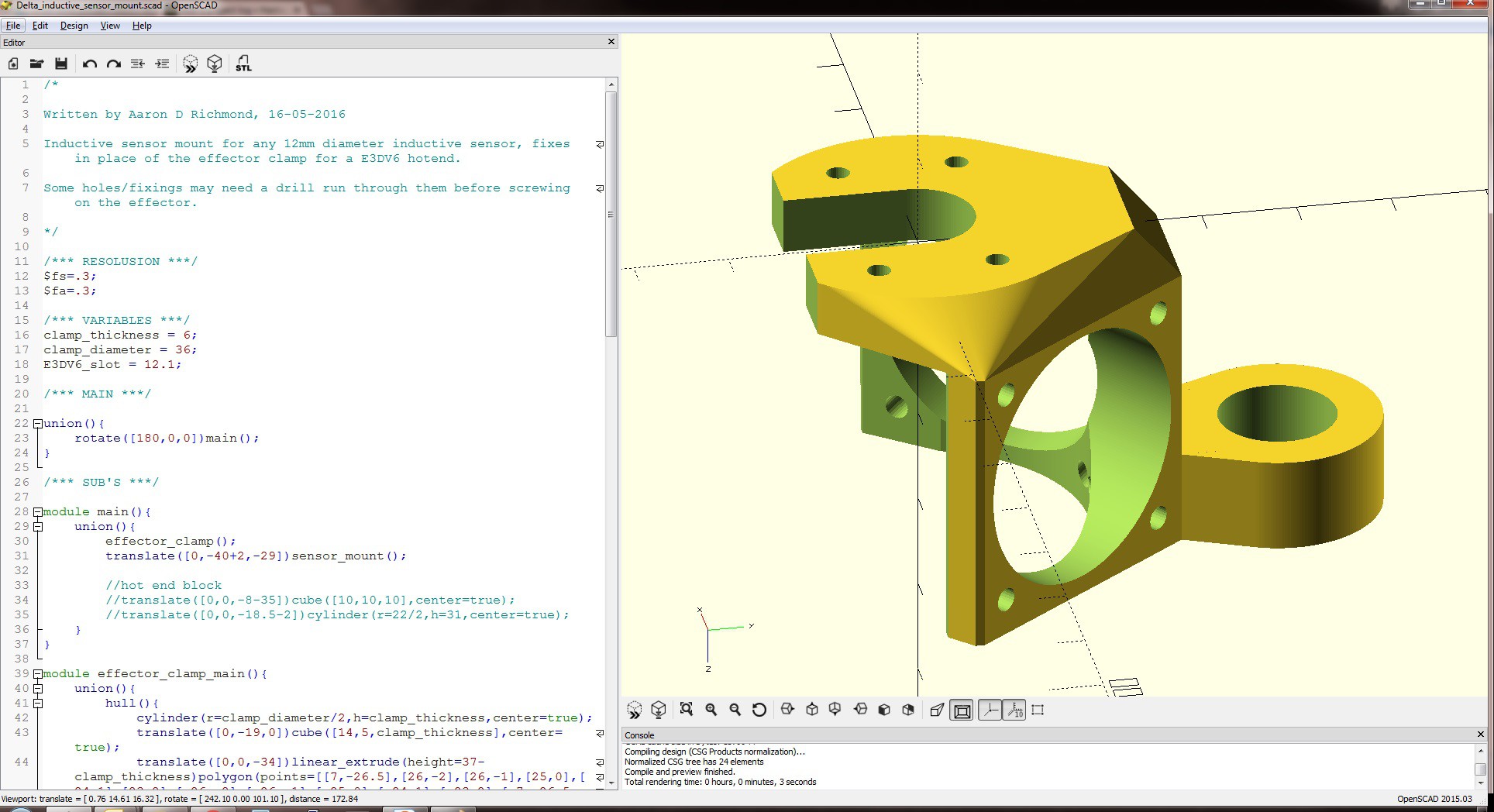
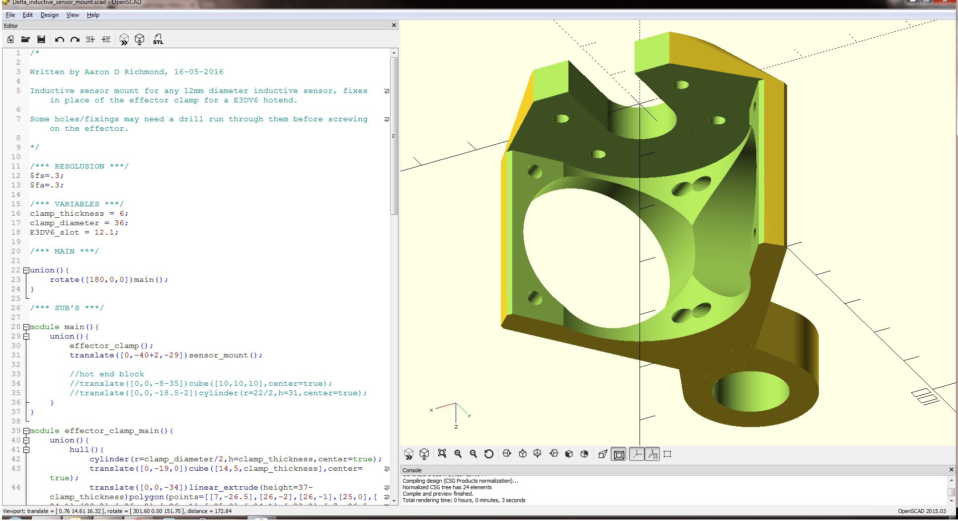
This is the 1st iteration of the inductive sensor mount i will use, it has 2x 30mm fan mounts built in to cool the to of the hot end. Again this is probably overkill and i will most likely change it for a single fan at some point.
![]()
This still leaves me space to add a fan to cool the plastics coming out of the hot end for bridging.
![]()
All drawn in openSCAD.
-
Tie rods
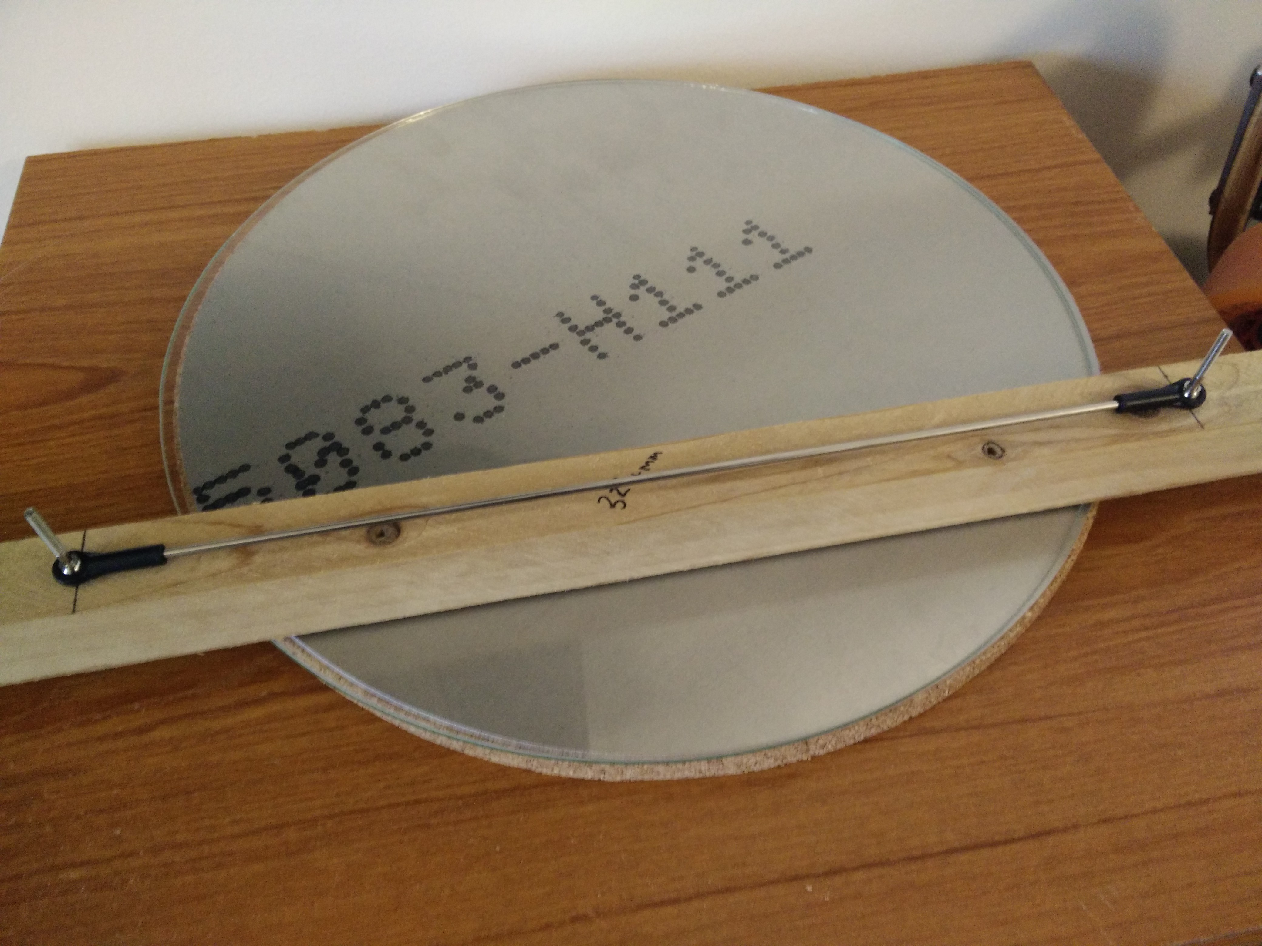
05/23/2016 at 12:12 • 0 commentsThe tie rods that link the effector onto the carriages need to be fairly accurate in length, i knocked up a simple jig for this using a bit of timber.
![]()
I used a drill press to put some straight 2.5mm holes in the wood and wound some m3 screws with a nice 3mm OD shank on them, probably a bit ott but it keeps my sanity in check. :)
-
Broken stepper driver
05/18/2016 at 14:41 • 0 commentsAfter fitting the belts i tested each axis to find that the Z stepper motor was only switching one set of coils on, i searched the PCB for dry joints but had no luck.
Option 1 is to buy another driver and re flow it onto the PCB
Option 2 is to buy a new MKS base
Option 3 is to utilize the second extruder driver (i do not want to go for dual extrusion anyways), i switched the pin around in the firmware. The file for the MKS base links the standard ramps file "pins_RAMPS_14.h", the result was....
#define Z_STEP_PIN 36
#define Z_DIR_PIN 34
#define Z_ENABLE_PIN 30
#define E1_STEP_PIN 46
#define E1_DIR_PIN 48
#define E1_ENABLE_PIN 62
I may still buy another A4988 driver and replace the broken one.
-
Update 18-05-2016
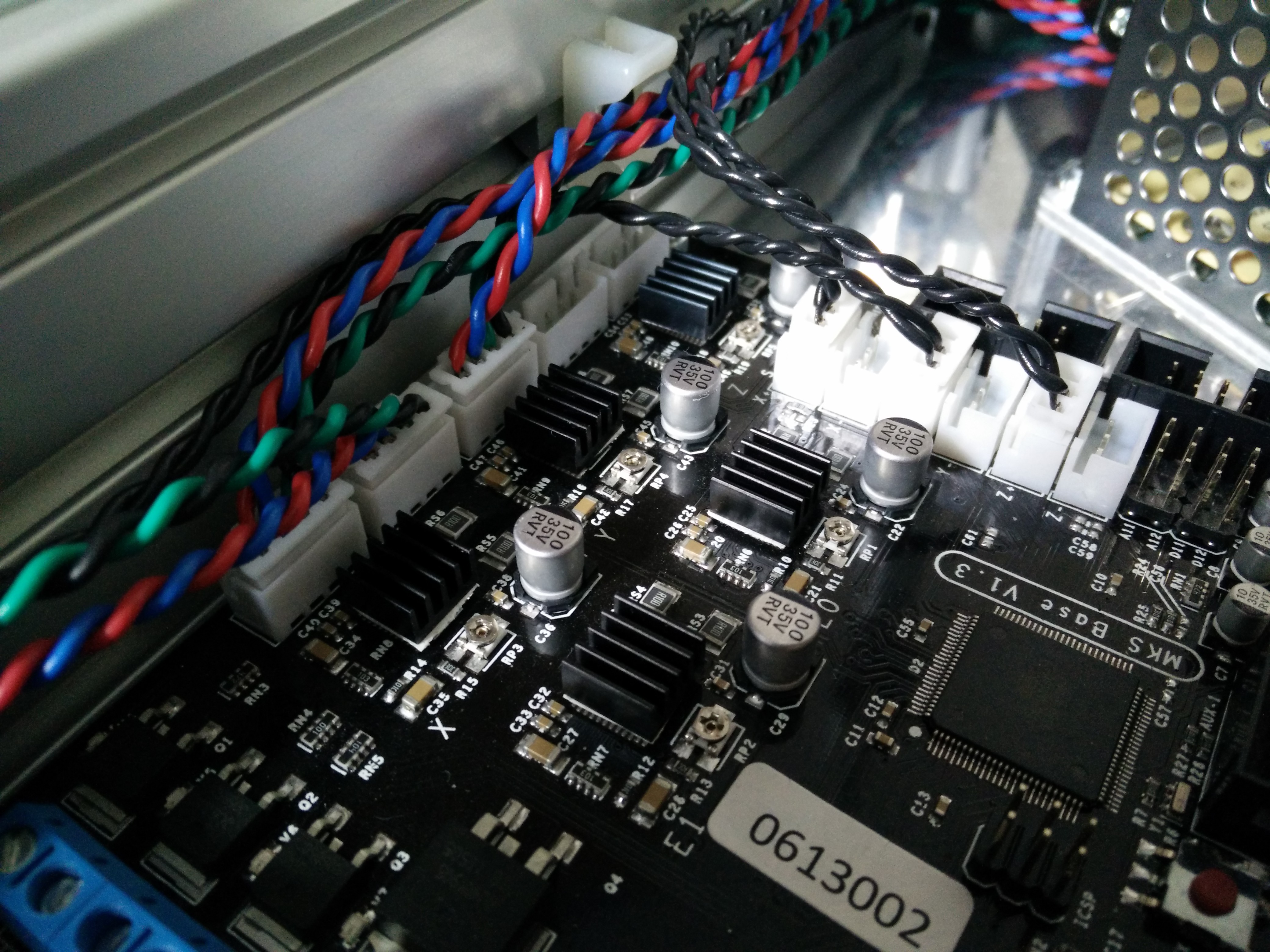
05/18/2016 at 14:24 • 0 commentsI have now finished the wiring for all the axis and have added some small heat sinks to the drivers.
![]()
I have started to fit the belts and put together my rods for the effector.
-
Install some components
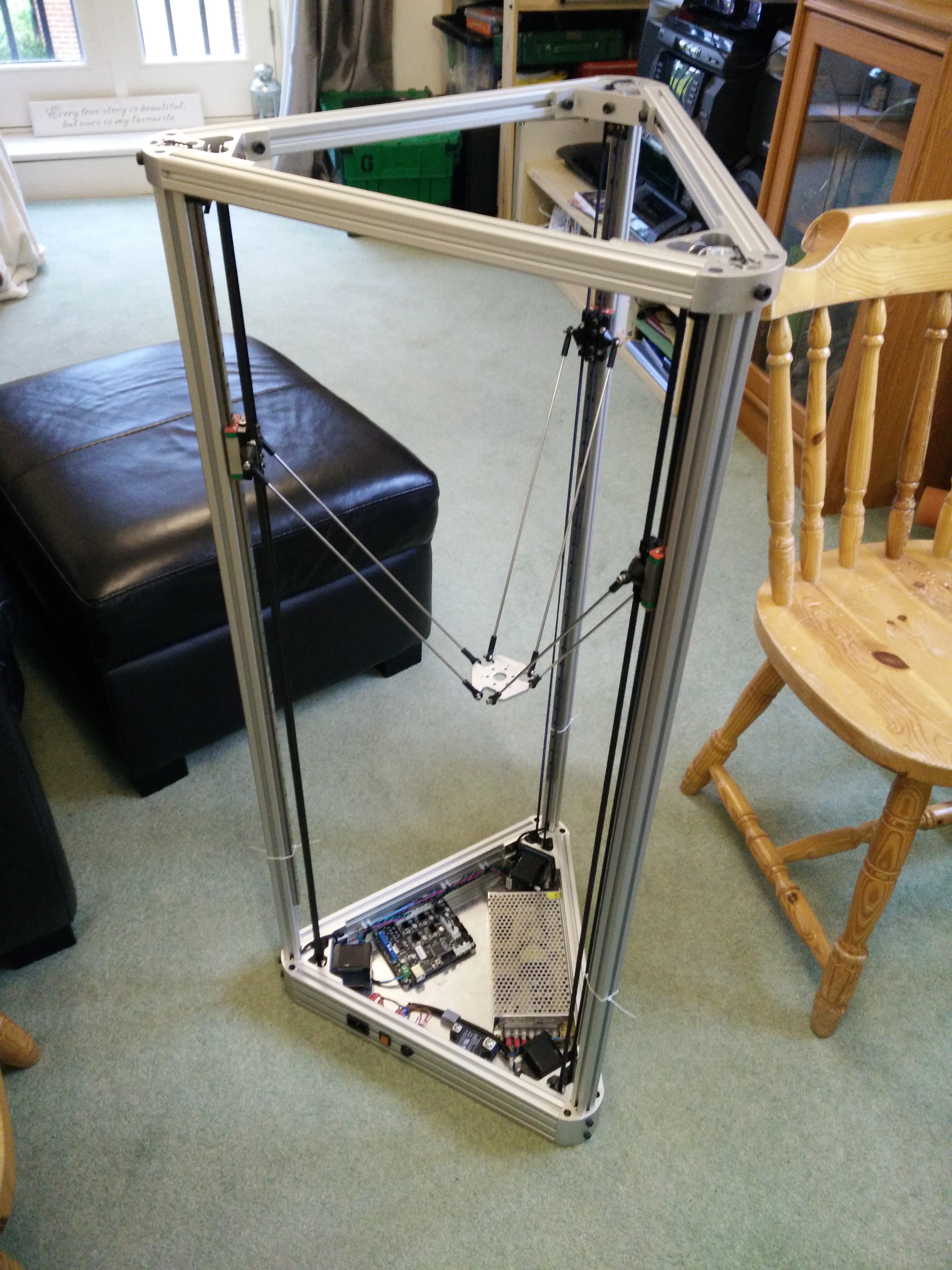
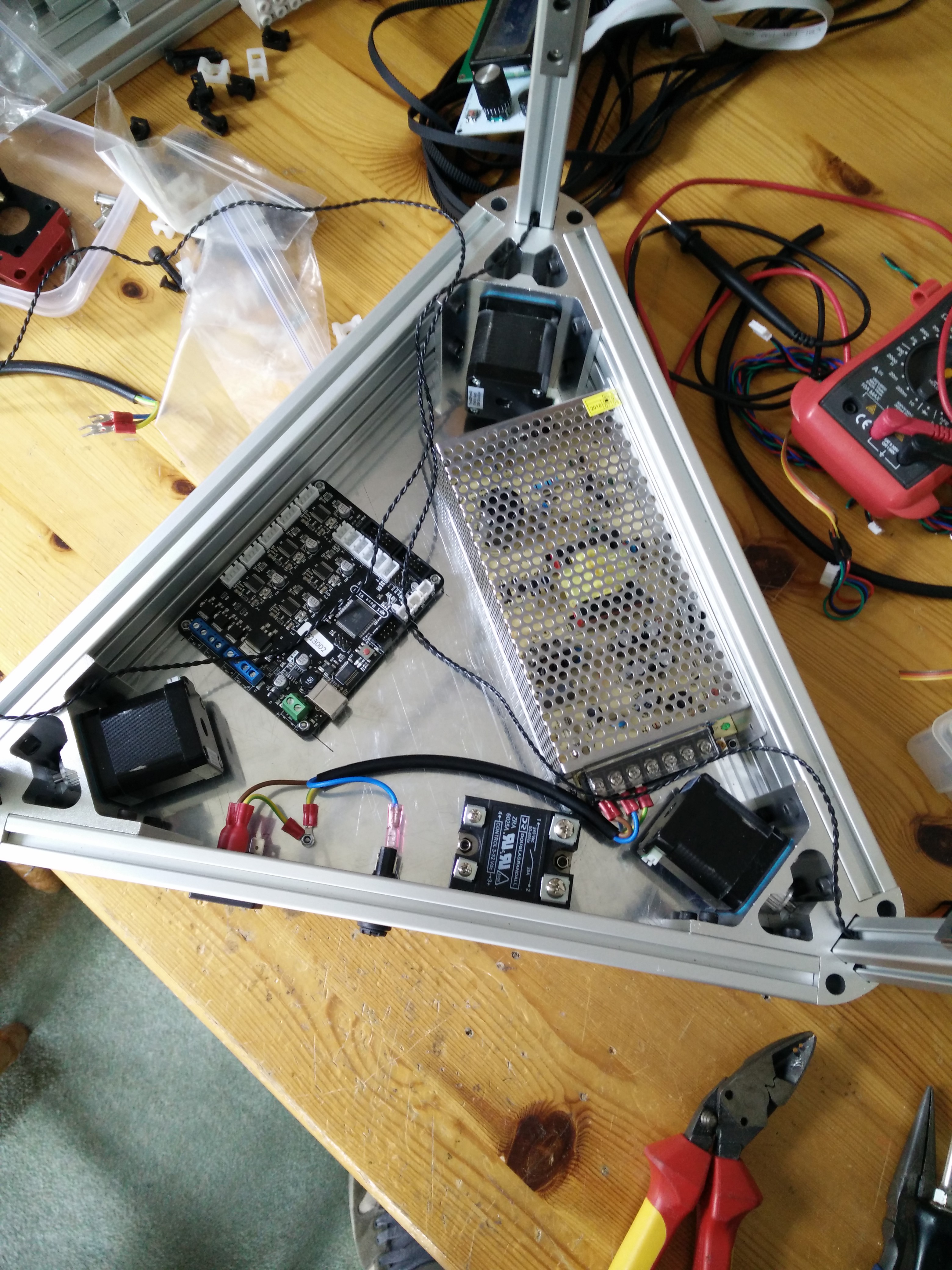
05/11/2016 at 16:25 • 0 commentsMounted some of the electronics into the base of the printer, there is not much room for that PSU but it does fit.
![]()
Need to source some tie wrap bases to route all the wiring nice and neatly, using this layout I should be able to keep all the mains wiring far away from the stepper wires and limit switches.
-
External connectors
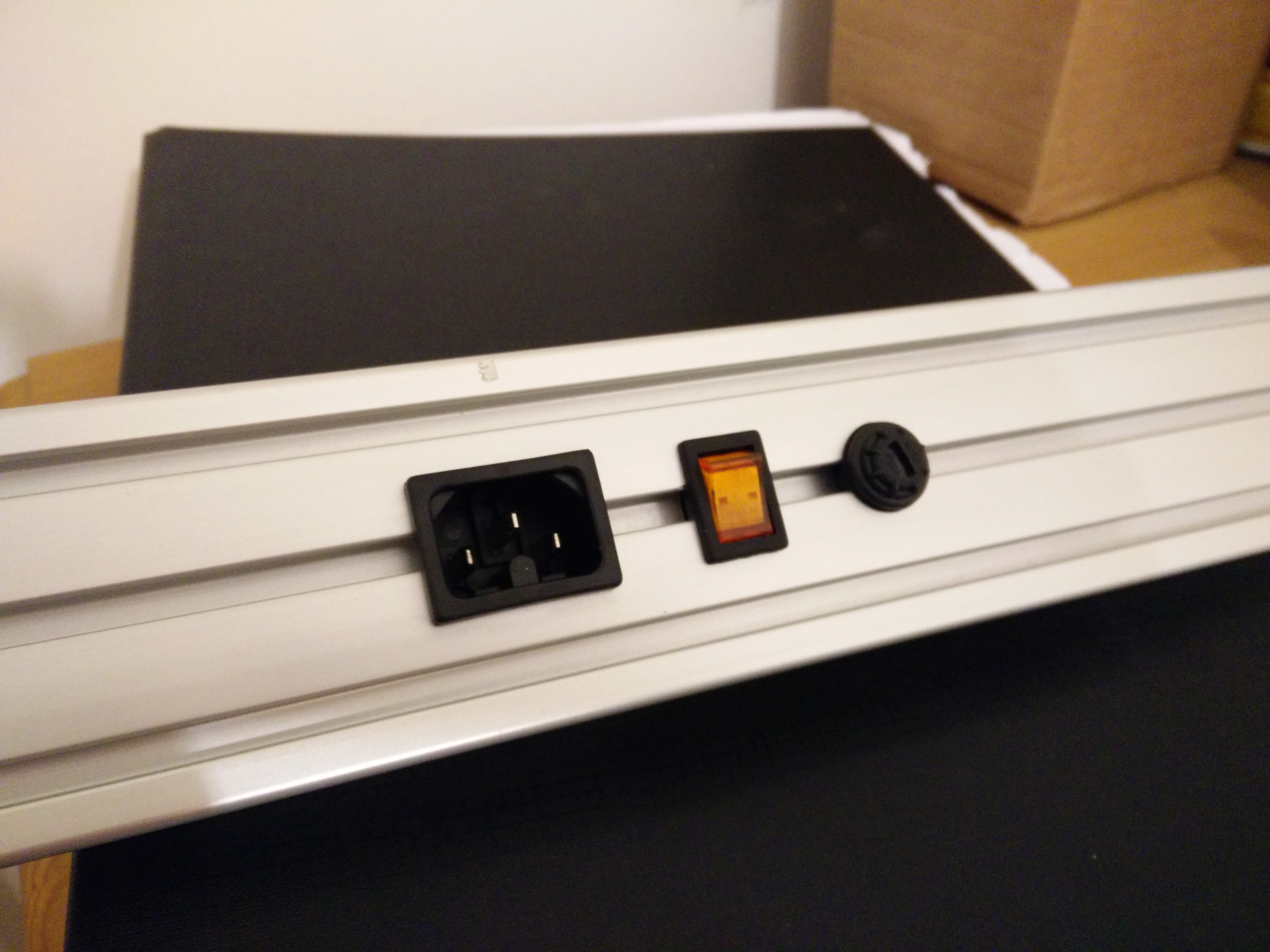
05/10/2016 at 12:16 • 0 commentsFor the print bed i am going to use a mains 240V heated bed, the switching will be done through an SSR (solid state relay). But i will need a place to plug the power in, a switch and a fuse for a bit of safety.
Using my drill and some files i managed to fit all 3 nicely together.
![]()
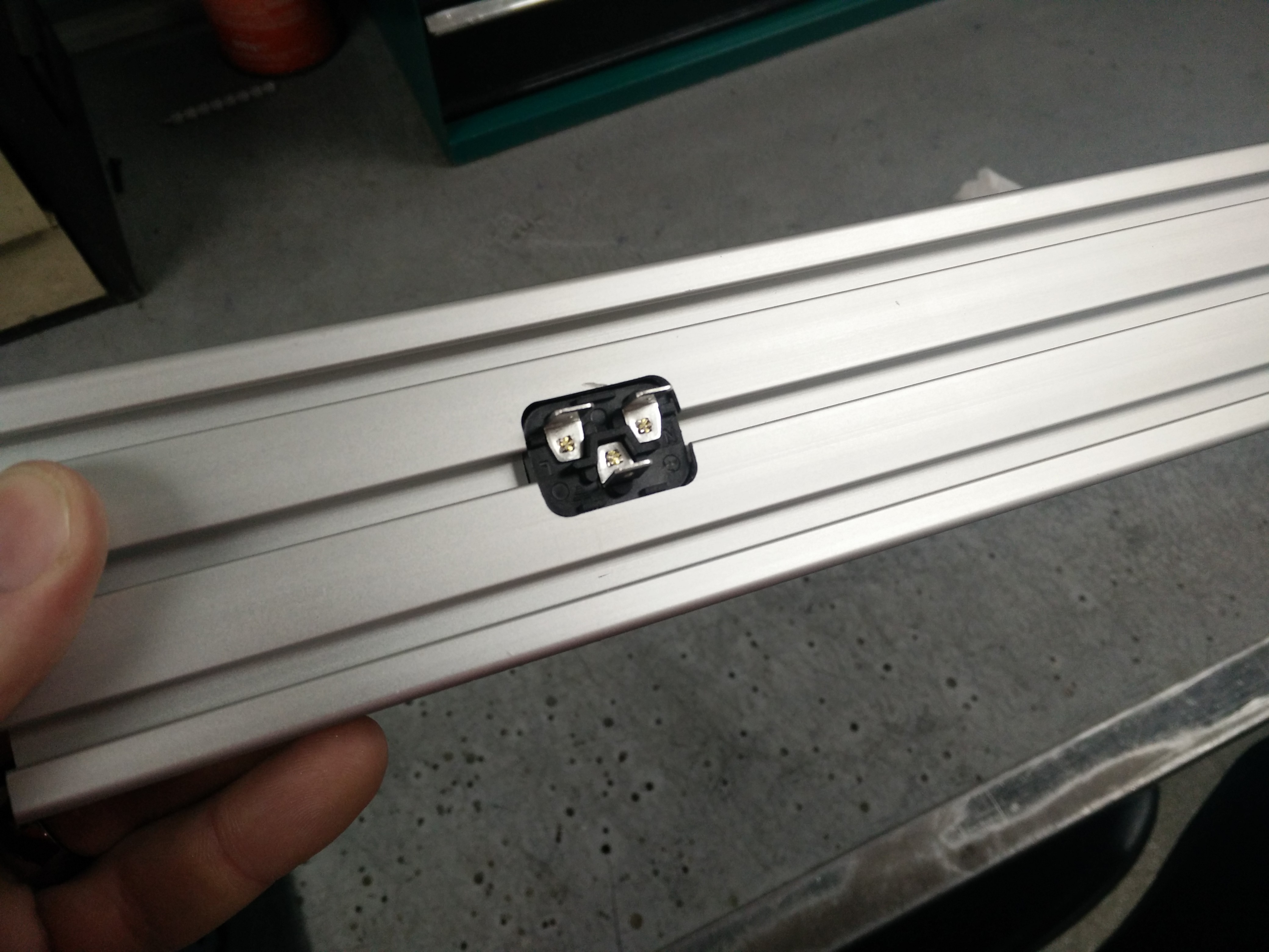
The back of the first one i mounted, not bad for some filework.
![]()
-
Base plate
05/10/2016 at 12:11 • 0 commentsI purchased a 450x400x3mm aluminium sheet off ebay for this bit, i cut the main shape out on a bandsaw and sanded the cut marks out.
![]()
I have already drilled and countersunk the screws in the bottom for all the extrusions and the components that will sit inside. I want this machine to be as clean as possible, i.e. no PSU strapped to the side :)
KOSSEL XXL
I wanted to build a large printer capable of printing PLA or ABS to a high quality, speed is also of major importance. (Mini Kossel based)
 Aaron Dominic Richmond