-
1Step 1
Create drilling templates for the front and base plates
Figure out how many 3.3V, 5V, 12V, -5V, and -12V banana jacks you want to have in your front plate. I used two each for the high-current voltages (3.3V, 5V, and 12V) and one each for the low-current ones (-5V and -12V, prepared a hole for -3.3V just in case I need it later).
The front plate will also hold a switch and two 3 mm LEDs (red for standby and green for power good). I also added holes for two cable glands.
Mark the positions of each hole on a piece of paper (or print the whole thing, it doesn't matter).
Do the same thing for mounting the front plate on the base plate. I used 4 M8 screws for that.
Here's a picture of my front template:
![]() It's missing the marks for the switch and the LEDs, I added them later.
It's missing the marks for the switch and the LEDs, I added them later. -
2Step 2
Drill front and base, mount front on base plate
Straight forward: My banana jacks needed 8 mm holes, the cable glands needed 12 mm-ish (12.5? I'm not sure what I used), then there's 5 mm for the switch and 3.2 mm for the LEDs, and finally 8.5 mm for the mounting screws:
![]() I used additional spring washers for the M8 screws.
I used additional spring washers for the M8 screws. -
3Step 3
Drill front and base, mount front on base plate
Straight forward: My banana jacks needed 8 mm holes, the cable glands needed 12 mm-ish (12.5? I'm not sure what I used), then there's 5 mm for the switch and 3.2 mm for the LEDs, and finally 8.5 mm for the mounting screws:
![]() I used additional spring washers for the M8 screws.
I used additional spring washers for the M8 screws. -
4Step 4
Mount the switch, banana jacks, cable glands, whatever else you include in your front plate.
I added the LEDs on their own little board later.
-
5Step 5
Prepare the cables that connect the banana jacks to the terminal strips.
Mine are 2.5 mm², about 20 cm long, and have a ring terminal and a cable sleeve:
![]() You can also see two cables (red and black) attached to the switch. They are used to tie the PS_ON signal to ground when the switch is flipped upwards (on). This wil enable the power supply.
You can also see two cables (red and black) attached to the switch. They are used to tie the PS_ON signal to ground when the switch is flipped upwards (on). This wil enable the power supply. -
6Step 6
Add terminal strips and mounting helpers to the base plate:
![]() I later replaced the terminal strips shown in the picture (6 mm²) with bigger ones (10 mm²) because they were simply easier to work with.
I later replaced the terminal strips shown in the picture (6 mm²) with bigger ones (10 mm²) because they were simply easier to work with.The PVC tubes are used to hold cable ties. Use anything you like for this purpose.
The ATX connector you see next to the base plate has not been cut off the power supply. It's one half of an ATX 2.2 -> ATX 2.1 adapter.
-
7Step 7
Prepare the adapters and connect them to the terminal strips
This part is important and tricky, and it took me three attempts to get this right. Here's the rules:
- Any high-current line must be a twin line that starts as a twin at the power supply's PCB because the single cables simply should be loaded with 15 A.
- We don't want any dangling cables
- The terminal strips provide 24 connections.
- We want (more less) simple access to all voltages for internal usage.
- It shouldn't matter if an ATX 2.1 or 2.2 supply is used.
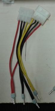
Prepare two pairs of HD adapters first. Two each are combined to privde high-current ground, 5V and 12V. This is one pair:
![]() Make two of these.
Make two of these.The ATX adapter
provides 3.3 V, the negative voltages and all the specials like Vsb, power good, PS on. Use twin sleeves for
- 8 ground lines (that's 4 x 2)
- 4 3.3V lines (2 x 2 plus a bridge to get an extra tap, see picture)
- 4 5V lines (2 x 2)
- 2 12V lines (1 x 2)
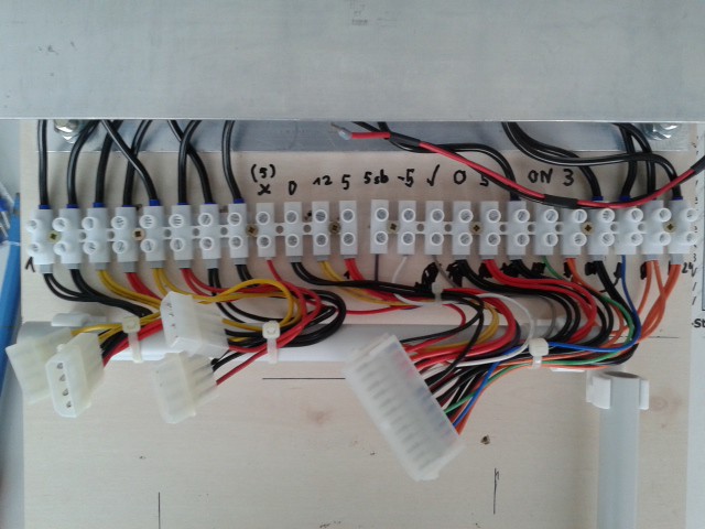
All other cables should get a single sleeve. Now connect everything, here's my result:
![]() The orange 3.3V lines are to the right. Can you see the orange bridge? That provides an additional 3.3V tap for internal use. The 5V line marked with an X is part of the ATX 2.2 extension and won't supply anything if an ATX 2.1 power supply is attached.
The orange 3.3V lines are to the right. Can you see the orange bridge? That provides an additional 3.3V tap for internal use. The 5V line marked with an X is part of the ATX 2.2 extension and won't supply anything if an ATX 2.1 power supply is attached. -
8Step 8
Build and mount the minimum load board
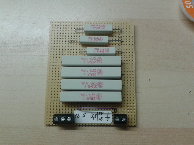
The minimum load board is a piece of stripboard that carries 5 screw terminals and the load resistors:
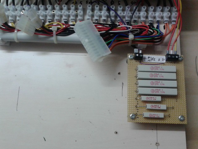
![]() Mounted with 4 screws and 20 mm spacers, and connected to the power supply. Note that I accidentally used the wrong 5V terminal (#9 from the left, this is part of the ATX 2.2 extension and my power supply is 2.1 or lower). I changed that later. The small PVC pipe you saw earlier has been removed to make space for the minimum load board:
Mounted with 4 screws and 20 mm spacers, and connected to the power supply. Note that I accidentally used the wrong 5V terminal (#9 from the left, this is part of the ATX 2.2 extension and my power supply is 2.1 or lower). I changed that later. The small PVC pipe you saw earlier has been removed to make space for the minimum load board:![]() Connections:
Connections:- 5Vsb from the terminal strips to the minimum load board and to the standby LED
- Ground from the terminal strips to the minimum load board and to the LED board
- 3.3 V, 5 V and 12 V from the terminal strips to the minimum load board
-
9Step 9
Add the Power Supply
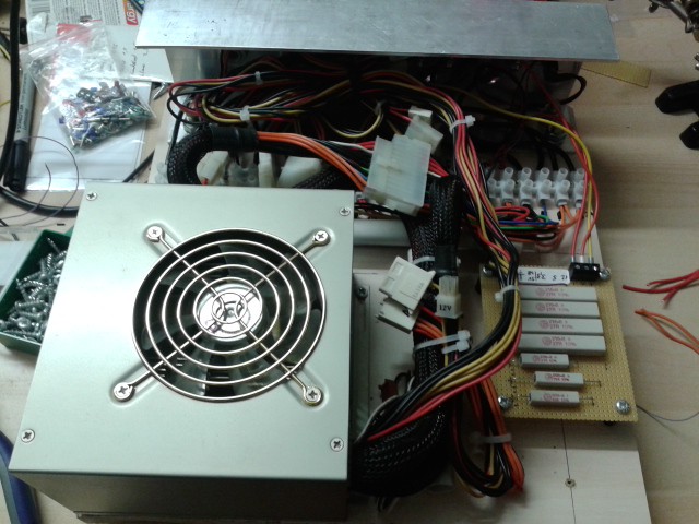
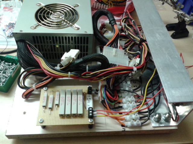
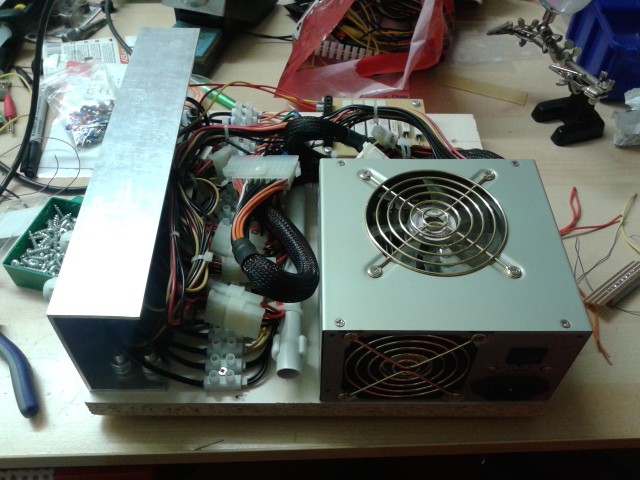
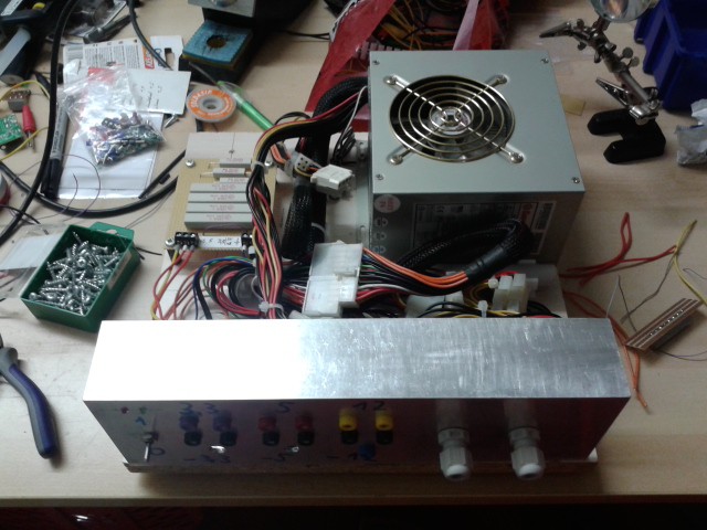
Mount the power supply with as many screws as you can (2 in my case...) and connect it. Take a ton of cable ties and try to make it look neat:
![]()
![]()
![]()
![]() That's it!
That's it! -
10Step 10
Test
Make sure that both the switch in the front plate and the power supply switch are off. Attach a cable to the power supply and switch it on. The standby LED should be on, indicating that 5Vsb is available. 5 Vsb should really be 5 V. The other outputs shouldn't source current now.
Turn on the front panel switch. After a short while the green LED (power good) should turn on, indicating that the power supply reports the output as stable.
Measure all output voltages (3.3 V, 5 V, 12 V, -5 V if available, -12 V if available). My power supply worked right away, so I can't tell what errors might occur..
ATX power supply conversion for bench usage
I'm converting an Enermax EG465AX-VE(G) into a bench power supply for my hacks.
 Christoph
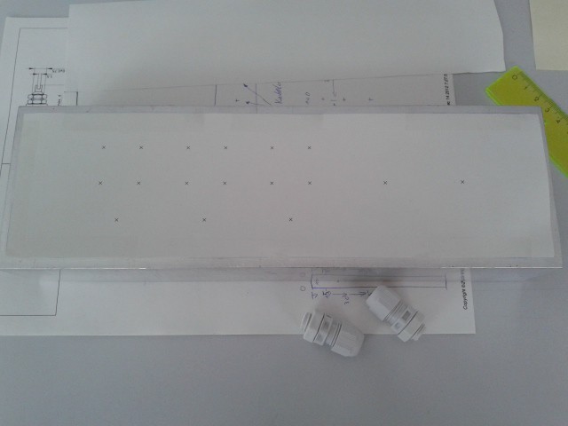 It's missing the marks for the switch and the LEDs, I added them later.
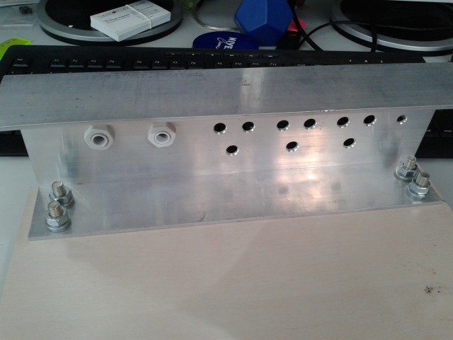 I used additional spring washers for the M8 screws.
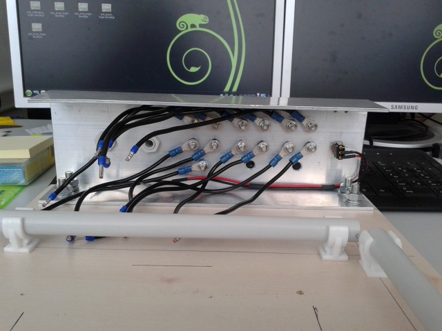 You can also see two cables (red and black) attached to the switch. They are used to tie the PS_ON signal to ground when the switch is flipped upwards (on). This wil enable the power supply.
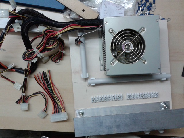 I later replaced the terminal strips shown in the picture (6 mm²) with bigger ones (10 mm²) because they were simply easier to work with.
 Make two of these.
 The orange 3.3V lines are to the right. Can you see the orange bridge? That provides an additional 3.3V tap for internal use. The 5V line marked with an X is part of the ATX 2.2 extension and won't supply anything if an ATX 2.1 power supply is attached.
 Mounted with 4 screws and 20 mm spacers, and connected to the power supply. Note that I accidentally used the wrong 5V terminal (#9 from the left, this is part of the ATX 2.2 extension and my power supply is 2.1 or lower). I changed that later. The small PVC pipe you saw earlier has been removed to make space for the minimum load board:
 Connections:
 That's it!
Discussions
Become a Hackaday.io Member
Create an account to leave a comment. Already have an account? Log In.